
ABB Semiconductors AG reserves the right to change specifications without notice.
V
RRM
=
5500 V
I
FAVM
=
380 A
I
FSM
=
10 kA
V
F0
=
2.7 V
r
F
=
2.8 m
V
DClink
=
3300 V
Doc. No. 5SYA1150-02 Sep. 01
∑ Patented free-floating technology
∑ Industry standard housing
∑ Cosmic radiation withstand rating
∑ Low on-state and switching losses
∑ Optimized to use in snubberless operation
Blocking
V
RRM
Repetitive peak reverse voltage
5500 V
Half sine wave, t
P
= 10 ms, f = 50 Hz
I
RRM
Repetitive peak reverse current
20 mA
V
R
= V
RRM,
T
j
= 115∞C
V
DClink
Permanent DC voltage for 100 FIT
failure rate
3300 V
100% Duty
V
DClink
Permanent DC voltage for 100 FIT
failure rate
3900 V
5% Duty
Ambient cosmic radiation at
sea level in open air.
Mechanical data
min.
18 kN
F
m
Mounting force
max.
22 kN
a
Acceleration:
Device unclamped
Device clamped
50
200
m/s
2
m/s
2
m
Weight
0.46 kg
D
S
Surface creepage distance
33 mm
D
a
Air strike distance
20 mm
Fast Recovery Diode
5SDF 04F6004
5SDF 04F6004
ABB Semiconductors AG reserves the right to change specifications without notice.
Doc. No. 5SYA1150-02 Sep. 01
page 2 of 5
On-state
(see Fig. 1, 2)
I
FAVM
Max. average on-state current
380 A
I
FRMS
Max. RMS on-state current
600 A
Half sine wave, T
c
= 70∞C
I
FSM
Max. peak non-repetitive
10 kA
tp
=
10 ms
Before surge:
surge current
22 kA
tp =
1 ms
T
c
= T
j
= 115∞C
0.5
10
6
A
2
s
tp =
10 ms
After surge:
ÚI
2
dt
Max. surge current integral
0.24
10
6
A
2
s
tp =
1 ms
V
R
0 V
V
F
Forward voltage drop
5.2 V
I
F
=
900 A
V
F0
Threshold voltage
2.7 V
Approximation for
r
F
Slope resistance
2.8 m
I
F
= 200...2000
A
T
j
= 115∞C
Turn-on
(see Fig. 3, 4)
V
fr
Peak forward recovery voltage
370 V
di/dt = 1000 A/µs, T
j
= 115∞C
Turn-off
di/dt
crit
Max. decay rate of on-state current
340 A/µs I
F
= 900 A,
T
j
= 115 ∞C
V
Dclink
= 3300 V
I
rr
Reverse recovery current
600 A
Q
rr
Reverse recovery charge
µC
E
rr
Turn-off energy
3.5 J
Thermal
T
j
Operating junction temperature range
-40...115∞C
T
stg
Storage temperature range
-40...125∞C
R
thJC
Thermal resistance junction to case
44 K/kW
Anode side cooled
44 K/kW
Cathode side cooled
22 K/kW
Double side cooled
R
thCH
Thermal resistance case to heatsink
10 K/kW
Single side cooled
F
m
=
18... 22 kN
5 K/kW
Double side cooled
Analytical function for transient thermal impedance.
i
1
2
3
4
R
i
(K/kW)
9.74
3.12
1.18
0.52
i
(s)
0.387
0.0457
0.006
0.0018
)
e
-
(1
R
=
(t)
Z
n
1
i
/
t
-
i
thJC
Â
=
i
F
m
= 18... 22 kN Double side cooled
5SDF 04F6004
ABB Semiconductors AG reserves the right to change specifications without notice.
Doc. No. 5SYA1150-02 Sep. 01
page 3 of 5
3
4
5
6
7
8
9
V
F
[V]
0
200
400
600
800
1000
1200
1400
1600
1800
2000
2200
I
F
[A]
Tj = 115∞C
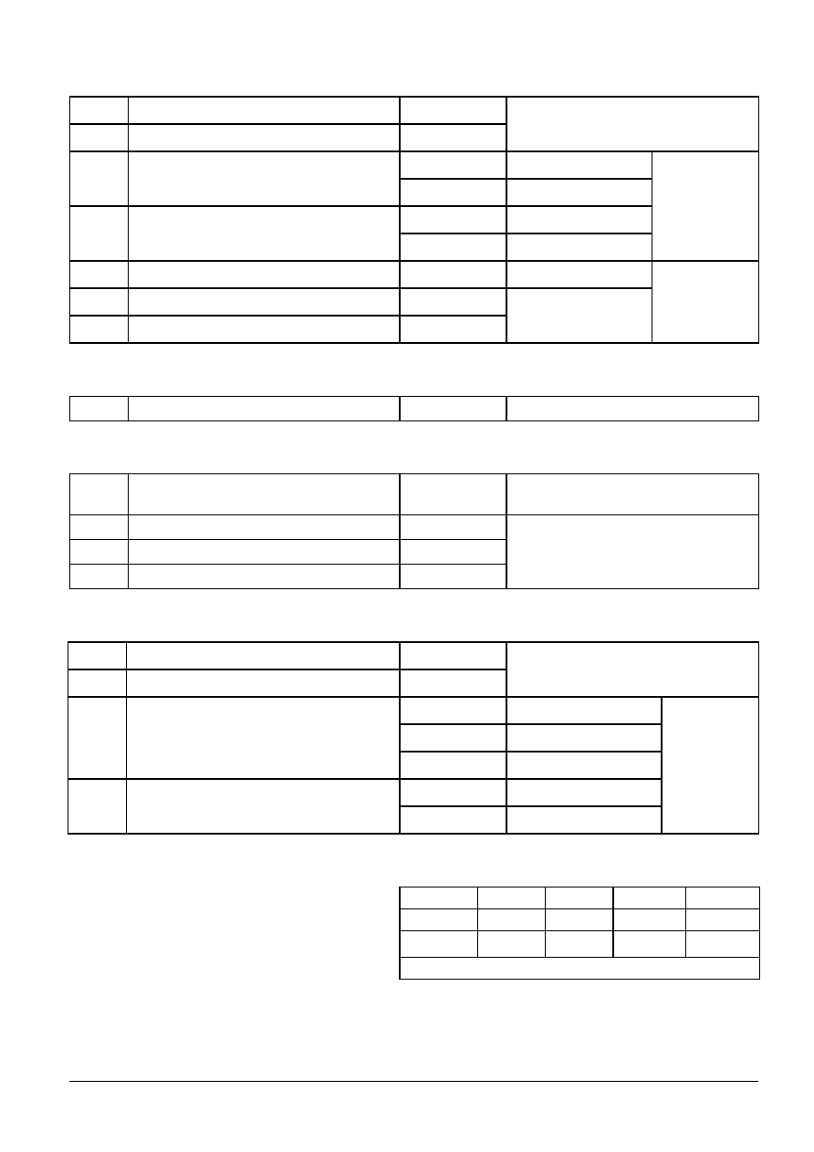
Fig. 1 Typical forward voltage waveform when
the diode is turned on with high di/dt.
Fig. 2 Forward current vs. forward voltage.
0
200
400
600
800
1000
I
FQ
[A]
0
100
200
300
400
500
600
700
I
rr
[A]
T
j
= 115∞C
di
F
/dt = 290 A/µs
V
DClink
= 3300 V
0
200
400
600
800
1000
I
FQ
[A]
0.0
0.5
1.0
1.5
2.0
2.5
3.0
3.5
4.0
E
rr
[J]
T
j
= 115∞C
di
F
/dt = 290 A/µs
V
DClink
= 3300 V
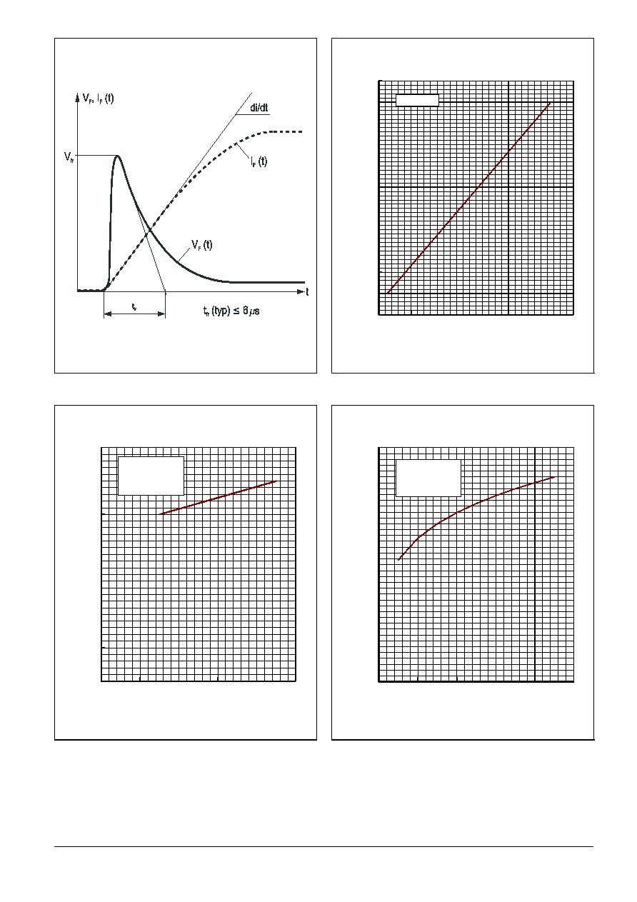
Fig. 3 Diode reverse recovery current vs. turn-
off current.
Fig. 4 Diode turn-off energy per pulse vs. turn-
off current.
5SDF 04F6004
ABB Semiconductors AG reserves the right to change specifications without notice.
Doc. No. 5SYA1150-02 Sep. 01
page 4 of 5
0
1000
2000
3000
4000
5000
V
DClink
[V]
0
100
200
300
400
500
600
700
800
900
1000
I
FQ
[A]
T
j
= 0 - 115∞C
di
F
/dt = 290 A/µs
V
RM
V
RRM
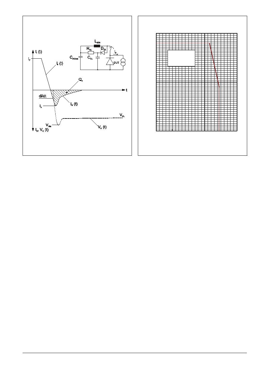
Fig. 5 Typical current and voltage waveforms at
turn-off in a circuit with voltage clamp.
Fig. 6 Max. repetitive diode forward current.
5SDF 04F6004
ABB Semiconductors AG reserves the right to change specifications without notice.
ABB Semiconductors AG
Doc. No. 5SYA1150-02 Sep. 01
Fabrikstrasse 3
CH-5600 Lenzburg, Switzerland
Telephone +41 (0)62 888 6419
Fax
+41 (0)62 888 6306
Email
abbsem@ch.abb.com
Internet
www.abbsem.com
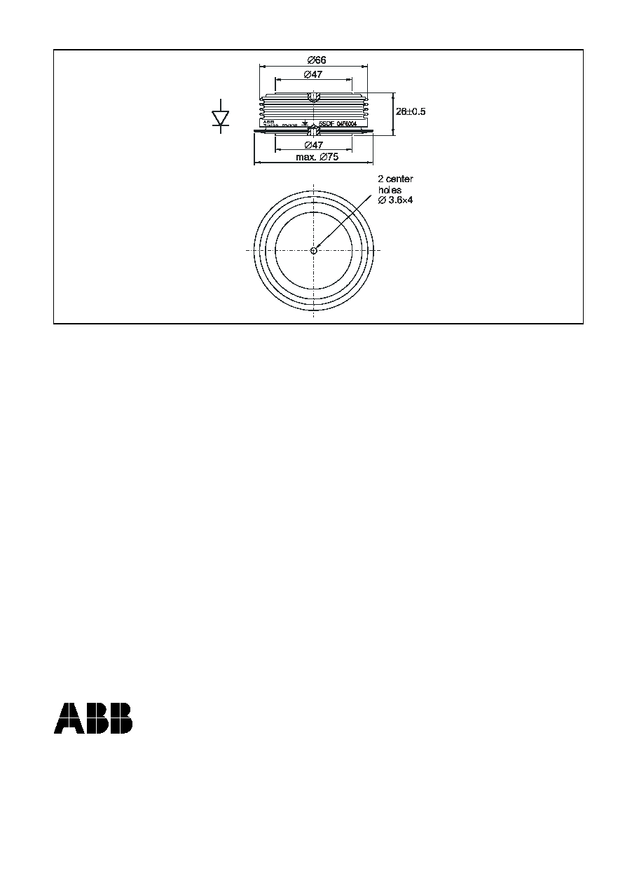
Fig. 7 Outline drawing. All dimensions are in millimeters and represent nominal values unless stated
otherwise.