 | ÐлекÑÑоннÑй компоненÑ: AD628ARZ1 | СкаÑаÑÑ:  PDF PDF  ZIP ZIP |
AD628 High Common-Mode Voltage, Programmable Gain Difference Amplifier Data Sheet (Rev. F)
High Common-Mode Voltage,
Programmable Gain Difference Amplifier
AD628
FEATURES
High common-mode input voltage range
±120 V at V
S
= ±15 V
Gain range 0.1 to 100
Operating temperature range: -40°C to ±85°C
Supply voltage range
Dual supply: ±2.25 V to ±18 V
Single supply: 4.5 V to 36 V
Excellent ac and dc performance
Offset temperature stability RTI: 10 V/°C maximum
Offset: ±1.5 V mV maximum
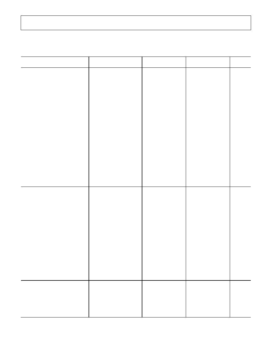
CMRR RTI: 75 dB minimum, dc to 500 Hz, G = +1
APPLICATIONS
High voltage current shunt sensing
Programmable logic controllers
Analog input front end signal conditioning
+5 V, +10 V, ±5 V, ±10 V, and 4 to 20 mA
Isolation
Sensor signal conditioning
Power supply monitoring
Electrohydraulic control
Motor control
GENERAL DESCRIPTION
The AD628 is a precision difference amplifier that combines
excellent dc performance with high common-mode rejection
over a wide range of frequencies. When used to scale high
voltages, it allows simple conversion of standard control
voltages or currents for use with single-supply ADCs. A
wideband feedback loop minimizes distortion effects due to
capacitor charging of - ADCs.
A reference pin (V
REF
) provides a dc offset for converting bipolar
to single-sided signals. The AD628 converts +5 V, +10 V, ±5 V,
±10 V, and 4 to 20 mA input signals to a single-ended output
within the input range of single-supply ADCs.
The AD628 has an input common-mode and differential-mode
operating range of ±120 V. The high common-mode input
impedance makes the device well suited for high voltage
measurements across a shunt resistor. The inverting input of the
buffer amplifier is available for making a remote Kelvin
connection.
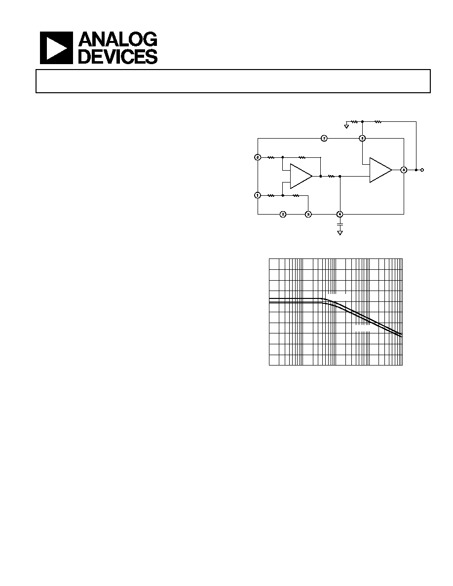
FUNCTIONAL BLOCK DIAGRAM
R
EXT1
R
EXT2
R
G
+V
S
+IN
IN
+IN
IN
V
S
A2
A1
+IN
IN
100k
100k
10k
10k
V
REF
10k
AD628
OUT
G = +0.1
C
FILT
02992-C
-
001
Figure 1.
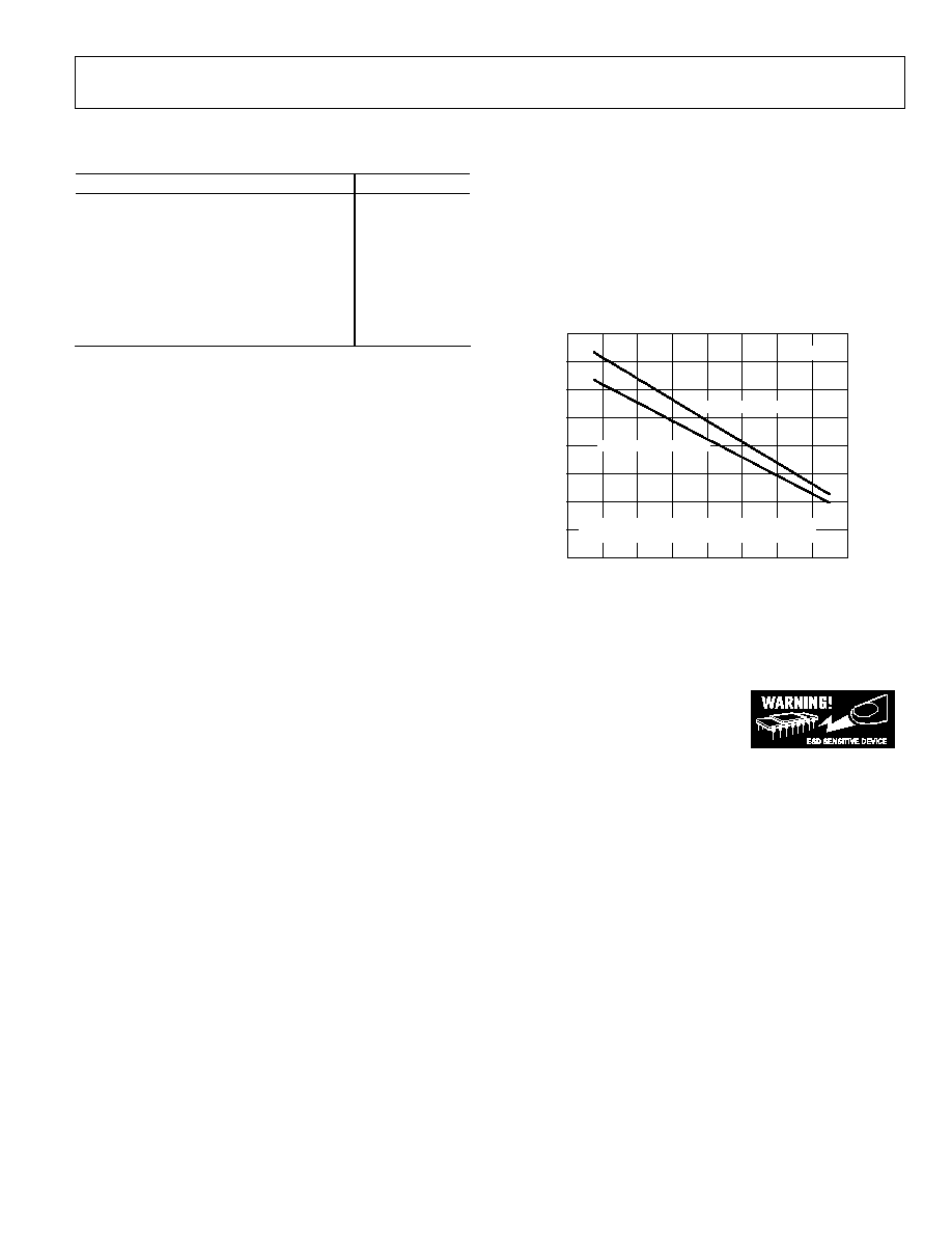
30
40
50
60
70
80
90
100
110
120
130
CMRR (dB)
FREQUENCY (Hz)
100
10
1k
10k
100k
02992-C-002
V
S
= ±2.5V
V
S
= ±15V
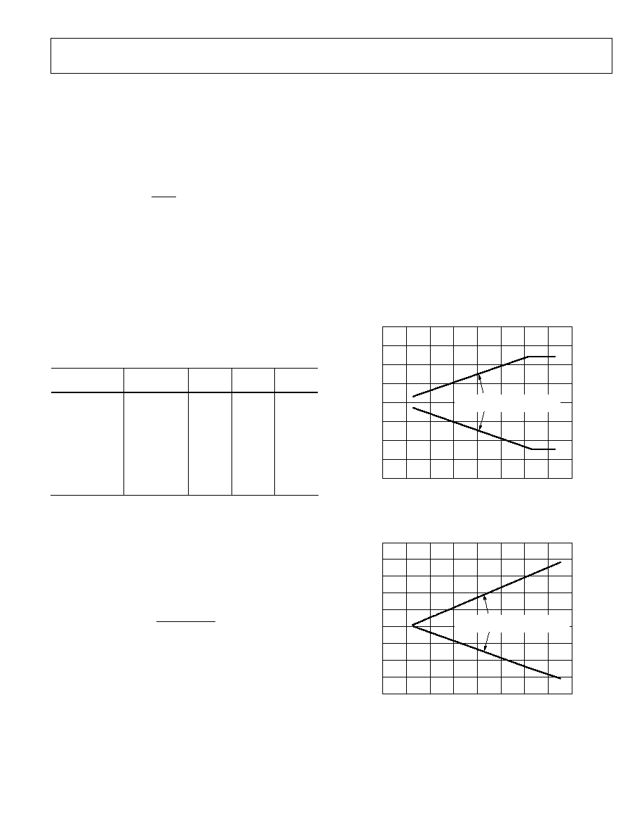
Figure 2. CMRR vs. Frequency of the AD628
A precision 10 k resistor connected to an external pin is
provided for either a low-pass filter or to attenuate large
differential input signals. A single capacitor implements a low-
pass filter. The AD628 operates from single and dual supplies
and is available in an 8-lead SOIC_N or 8-lead MSOP package.
It operates over the standard industrial temperature range of
-40°C to +85°C.
Rev. F
Information furnished by Analog Devices is believed to be accurate and reliable. However, no
responsibility is assumed by Analog Devices for its use, nor for any infringements of patents or other
rights of third parties that may result from its use. Specifications subject to change without notice. No
license is granted by implication or otherwise under any patent or patent rights of Analog Devices.
Trademarks and registered trademarks are the property of their respective owners.
One Technology Way, P.O. Box 9106, Norwood, MA 02062-9106, U.S.A.
Tel: 781.329.4700
www.analog.com
Fax: 781.461.3113
©2006 Analog Devices, Inc. All rights reserved.

AD628
Rev. F | Page 2 of 20
TABLE OF CONTENTS
Features .............................................................................................. 1
Applications....................................................................................... 1
General Description ......................................................................... 1
Functional Block Diagram .............................................................. 1
Revision History ............................................................................... 2
Specifications..................................................................................... 3
Absolute Maximum Ratings............................................................ 7
Thermal Characteristics .............................................................. 7
ESD Caution.................................................................................. 7
Pin Configuration and Function Descriptions............................. 8
Typical Performance Characteristics ............................................. 9
Test Circuits..................................................................................... 13
Theory of Operation ...................................................................... 14
Applications..................................................................................... 15
Gain Adjustment ........................................................................ 15
Input Voltage Range................................................................... 15
Voltage Level Conversion.......................................................... 16
Current Loop Receiver .............................................................. 17
Monitoring Battery Voltages..................................................... 17
Filter Capacitor Values............................................................... 18
Kelvin Connection ..................................................................... 18
Outline Dimensions ....................................................................... 19
Ordering Guide .......................................................................... 19
REVISION HISTORY
3/06--Rev. E to Rev. F
Changes to Table 1............................................................................ 3
Changes to Figure 3.......................................................................... 7
Replaced Voltage Level Conversion Section ............................... 16
Changes to Figure 32 and Figure 33............................................. 17
Updated Outline Dimensions ....................................................... 19
Changes to Ordering Guide .......................................................... 19
5/05--Rev. D to Rev. E
Changes to Table 1........................................................................... 3
Changes to Table 2........................................................................... 5
Changes to Figure 33..................................................................... 18
3/05--Rev. C to Rev. D
Updated Format................................................................ Universal
Changes to Table 1........................................................................... 3
Changes to Table 2........................................................................... 5
4/04--Rev. B to Rev. C
Updated Format................................................................ Universal
Changes to Specifications ............................................................... 3
Changes to Absolute Maximum Ratings ...................................... 7
Changes to Figure 3......................................................................... 7
Changes to Figure 26..................................................................... 13
Changes to Figure 27..................................................................... 13
Changes to Theory of Operation................................................. 14
Changes to Figure 29..................................................................... 14
Changes to Table 5......................................................................... 15
Changes to Gain Adjustment Section......................................... 15
Added the Input Voltage Range Section..................................... 15
Added Figure 30 ............................................................................ 15
Added Figure 31 ............................................................................ 15
Changes to Voltage Level Conversion Section .......................... 16
Changes to Figure 32..................................................................... 16
Changes to Table 6......................................................................... 16
Changes to Figure 33 and Figure 34............................................ 17
Changes to Figure 35..................................................................... 18
Changes to Kelvin Connection Section...................................... 18
6/03--Rev. A to Rev. B
Changes to General Description ................................................... 1
Changes to Specifications............................................................... 2
Changes to Ordering Guide ........................................................... 4
Changes to TPCs 4, 5, and 6 .......................................................... 5
Changes to TPC 9............................................................................ 6
Updated Outline Dimensions...................................................... 14
1/03--Rev. 0 to Rev. A
Change to Ordering Guide............................................................. 4
11/02--Rev. 0: Initial Version
AD628
Rev. F | Page 3 of 20
SPECIFICATIONS
T
A
= 25°C, V
S
= ±15 V, R
L
= 2 k, R
EXT1
= 10 k, R
EXT2
= , V
REF
= 0, unless otherwise noted.
Table 1.
AD628AR
AD628ARM
Parameter
Conditions
Min
Typ
Max
Min
Typ
Max
Unit
DIFFERENTIAL
AND
OUTPUT
AMPLIFIER
Gain Equation
G = +0.1(1+ R
EXT1
/R
EXT2
)
V/V
Gain Range
See Figure 29
0.1
1
100
0.1
1
100
V/V
Offset Voltage
V
CM
= 0 V; RTI of input pins
2
;
output amplifier G = +1
-1.5
+1.5
-1.5
+1.5
mV
vs. Temperature
4
8
4
8
V/°C
CMRR
3
RTI of input pins;
G = +0.1 to +100
75
75
dB
500
Hz
75
75
dB
Minimum CMRR Over Temperature -40°C to +85°C
70
70
dB
vs. Temperature
1
4
1
4
(V/V)/°C
PSRR (RTI)
V
S
= ±10 V to ±18 V
77
94
77
94
dB
Input
Voltage
Range
Common Mode
-120
+120
-120
+120
V
Differential
-120
+120
-120
+120
V
Dynamic
Response
Small Signal Bandwidth -3 dB
G = +0.1
600
600
kHz
Full Power Bandwidth
5
5
kHz
Settling Time
G = +0.1, to 0.01%, 100 V step
40
40
s
Slew Rate
0.3
0.3
V/s
Noise
(RTI)
Spectral Density
1 kHz
300
300
nV/Hz
0.1 Hz to 10 Hz
15
15
V p-p
DIFFERENTIAL
AMPLIFIER
Gain
0.1
0.1
V/V
Error
-0.1
+0.01
+0.1
-0.1
+0.01
+0.1
%
vs. Temperature
5
5
ppm/°C
Nonlinearity
5
5
ppm
vs. Temperature
3
10
3
10
ppm
Offset Voltage
RTI of input pins
-1.5
+1.5
-1.5
+1.5
mV
vs.
Temperature
8
8
V/°C
Input
Impedance
Differential
220
220
k
Common Mode
55
55
k
CMRR
4
RTI of input pins;
G = +0.1 to +100
75
75
dB
500 Hz
75
75
dB
Minimum CMRR Over Temperature -40°C to +85°C
70
70
dB
vs. Temperature
1
4
1
4
(V/V)/°C
Output Resistance
10
10
k
Error
-0.1
+0.1
-0.1
+0.1
%
OUTPUT
AMPLIFIER
Gain Equation
G = (1 + R
EXT1
/R
EXT2
)
V/V
Nonlinearity
G = +1, V
OUT
= ±10 V
0.5
0.5
ppm
Offset Voltage
RTI of output amp
-0.15
+0.15
-0.15
+0.15
mV
vs.
Temperature
0.6
0.6
V/°C
Output Voltage Swing
R
L
= 10 k
-14.2
+14.1
-14.2
+14.1
V
R
L
= 2 k
-13.8
+13.6
-13.8
+13.6
V
AD628
Rev. F | Page 4 of 20
AD628ARM
AD628AR
Parameter
Conditions
Min
Typ
Max
Min
Typ
Max
Unit
Bias Current
1.5
3
1.5
3
nA
Offset Current
0.2
0.5
0.2
0.5
nA
CMRR
V
CM
= ±13 V
130
130
dB
Open-Loop Gain
V
OUT
= ±13 V
130
130
dB
POWER
SUPPLY
Operating Range
±2.25
±18
±2.25
±18
V
Quiescent Current
1.6
1.6
mA
TEMPERATURE RANGE
-40
+85
-40
+85
°C
1
To use a lower gain, see the Ga
section.
in Adjustment
2
The addition of the difference amplifier and output amplifier offset voltage does not exceed this specification.
3
Error due to common mode as seen at the output:
]
[
]
10
)
(0.1)(
[
20
75
Gain
Amplifier
Output
V
CM
OUT
×
=
V
4
Error due to common mode as seen at the output of A1:
]
10
)
(0.1)(
[
20
75
CM
OUT
V
A1 =
V

AD628
Rev. F | Page 5 of 20
T
A
= 25°C, V
S
= 5 V, R
L
= 2 k, R
EXT1
= 10 k, R
EXT2
= , V
REF
= 2.5, unless otherwise noted.
Table 2.
AD628AR
AD628ARM
Parameter
Conditions
Min Typ Max
Min Typ Max
Unit
DIFFERENTIAL
AND
OUTPUT
AMPLIFIER
Gain Equation
G = +0.1(1+ R
EXT1
/R
EXT2
)
V/V
Gain Range
See Figure 29
0.1
1
100
0.1
1
100
V/V
Offset Voltage
V
CM
= 2.25 V; RTI of input pins
2
;
output amplifier G = +1
-3.0
+3.0 -3.0
+3.0
mV
vs. Temperature
6
15
6
15
V/°C
CMRR
3
RTI of input pins; G = +0.1 to +100
75
75
dB
500 Hz
75
75
dB
Minimum CMRR Over Temperature
-40°C to +85°C
70
70
dB
vs. Temperature
1
4
1
4
(V/V)/°C
PSRR (RTI)
V
S
= 4.5 V to 10 V
77
94
77
94
dB
Input
Voltage
Range
Common Mode
4
-12
+17
-12
+17
V
Differential
-15
+15
-15
+15
V
Dynamic
Response
Small Signal Bandwidth 3 dB
G = +0.1
440
440
kHz
Full Power Bandwidth
30
30
kHz
Settling Time
G = +0.1; to 0.01%, 30 V step
15
15
s
Slew Rate
0.3
0.3
V/s
Noise
(RTI)
Spectral Density
1 kHz
350
350
nV/Hz
0.1 Hz to 10 Hz
15
15
V p-p
DIFFERENTIAL
AMPLIFIER
Gain
0.1
0.1
V/V
Error
0.1
+0.01
+0.1 0.1
+0.01
+0.1
%
Nonlinearity
3
3
ppm
vs. Temperature
3
10
3
10
ppm
Offset Voltage
RTI of input pins
-2.5
+2.5 -2.5
+2.5
mV
vs.
Temperature
10
10
V/°C
Input
Impedance
Differential
220
220
k
Common Mode
55
55
k
CMRR
5
RTI of input pins; G = +0.1 to +100
75
75
dB
500 Hz
75
75
dB
Minimum CMRR Over Temperature
-40°C to +85°C
70
70
dB
vs. Temperature
1
4
1
4
(V/V)/°C
Output Resistance
10
10
k
Error
-0.1
+0.1 -0.1
+0.1
%
OUTPUT
AMPLIFIER
Gain Equation
G = (1 + R
EXT1
/R
EXT2
)
V/V
Nonlinearity
G = +1, V
OUT
= 1 V to 4 V
0.5
0.5
ppm
Output Offset Voltage
RTI of output amplifier
-0.15
0.15
-0.15
0.15
mV
vs.
Temperature
0.6
0.6
V/°C
Output Voltage Swing
R
L
= 10 k
0.9
4.1
0.9
4.1
V
R
L
= 2 k
1
4
1
4
V
Bias Current
1.5
3
1.5
3
nA
Offset Current
0.2
0.5
0.2
0.5
nA
CMRR
V
CM
= 1 V to 4 V
130
130
dB
Open-Loop Gain
V
OUT
= 1 V to 4 V
130
130
dB
AD628
Rev. F | Page 6 of 20
AD628ARM
AD628AR
Parameter
Conditions
Min Typ Max
Min Typ Max
Unit
POWER
SUPPLY
Operating Range
±2.25
+36
±2.25
+36
V
Quiescent
Current
1.6
1.6
mA
TEMPERATURE RANGE
-40
+85
-40
+85
°C
1
To use a lower gain, see the Gain Adjustment section.
2
The addition of the difference amplifier and output amplifier offset voltage does not exceed this specification.
3
Error due to common mode as seen at the output:
]
[
]
10
)
(0.1)(
[
20
75
Gain
Amplifier
Output
V
CM
OUT
×
=
V
4
Greater values of voltage are possible with greater or lesser values of V
REF
.
5
Error due to common mode as seen at the output of A1:
]
10
)
(0.1)(
[
20
75
CM
OUT
V
A1 =
V
AD628
Rev. F | Page 7 of 20
ABSOLUTE MAXIMUM RATINGS
Table 3.
Parameter Rating
Supply Voltage
±18 V
Internal Power Dissipation
See Figure 3
Input Voltage (Common Mode)
±120 V
1
Differential Input Voltage
±120 V
1
Output Short-Circuit Duration
Indefinite
Storage Temperature
-65°C to +125°C
Operating Temperature Range
40°C to +85°C
Lead Temperature (Soldering, 10 sec)
300°C
1
When using ±12 V supplies or higher (see the In
section).
put Voltage Range
Stresses greater than those listed under Absolute Maximum
Ratings may cause permanent damage to the device. This is a
stress rating only; functional operation of the device at these or
any other conditions above those indicated in the operational
section of this specification is not implied. Exposure to absolute
maximum rating conditions for extended periods may affect
device reliability.
THERMAL CHARACTERISTICS
0
0.2
0.4
0.6
0.8
1.0
P
O
W
E
R DI
S
S
I
P
A
T
I
O
N (
W
)
1.2
1.4
1.6
20
0
40
20
60
40
60
80
100
AMBIENT TEMPERATURE (°C)
02
99
2-
C
-
00
3
8-LEAD SOIC PACKAGE
8-LEAD MSOP PACKAGE
T
J
= 150°C
MSOP
JA
(JEDEC; 4-LAYER BOARD) = 132.54°C/W
SOIC
JA
(JEDEC; 4-LAYER BOARD) = 154°C/W
Figure 3. Maximum Power Dissipation vs. Temperature
ESD CAUTION
ESD (electrostatic discharge) sensitive device. Electrostatic charges as high as 4000 V readily accumulate on
the human body and test equipment and can discharge without detection. Although this product features
proprietary ESD protection circuitry, permanent damage may occur on devices subjected to high energy
electrostatic discharges. Therefore, proper ESD precautions are recommended to avoid performance
degradation or loss of functionality.
AD628
Rev. F | Page 8 of 20
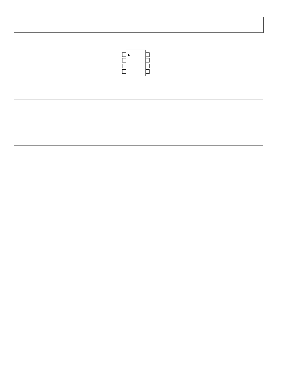
PIN CONFIGURATION AND FUNCTION DESCRIPTIONS
TOP VIEW
(Not to Scale)
8
7
6
5
1
2
3
4
+IN
V
S
V
REF
C
FILT
IN
+V
S
R
G
OUT
AD628
02992-C-004
Figure 4. Pin Configuration
Table 4. Pin Function Descriptions
Pin No.
Mnemonic
Descriptions
1
+IN
Noninverting Input
2
-V
S
Negative Supply Voltage
3
V
REF
Reference Voltage Input
4
C
FILT
Filter Capacitor Connection
5
OUT
Amplifier Output
6
R
G
Output Amplifier Inverting Input
7
+V
S
Positive Supply Voltage
8
-IN
Inverting Input
AD628
Rev. F | Page 9 of 20
TYPICAL PERFORMANCE CHARACTERISTICS
0
5
10
15
20
25
% OF UNITS
30
35
40
1.6
1.2
0.8
0.4
0
0.4
0.8
1.2
1.6
2.0
INPUT OFFSET VOLTAGE (mV)
02992-C-005
8440 UNITS
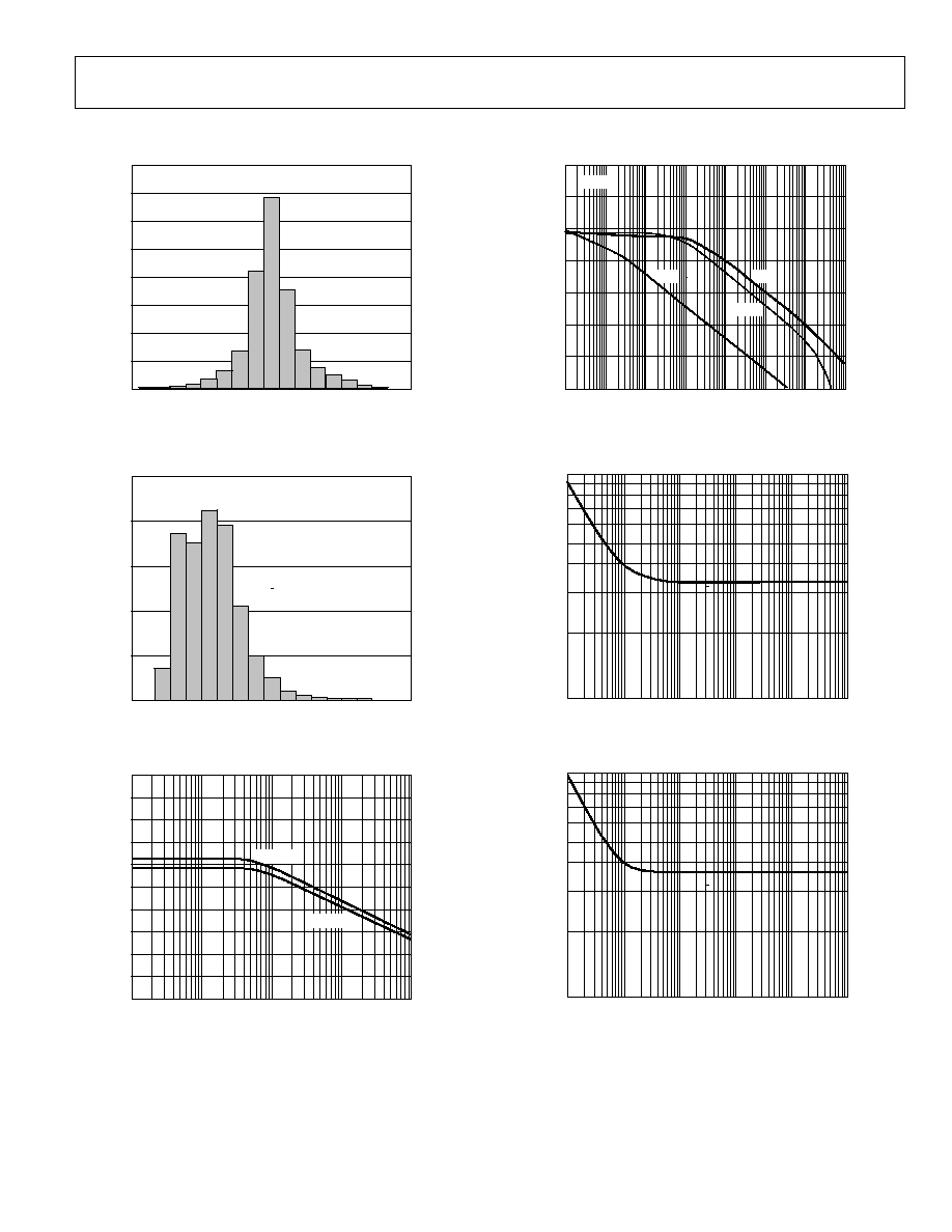
Figure 5. Typical Distribution of Input Offset Voltage,
V
S
= ±15 V, SOIC_N Package
0
5
10
15
20
25
% OF UNITS
74
78
82
86
90
94
98
102 106 110
CMRR (dB)
02992-C-006
8440 UNITS
Figure 6. Typical Distribution of Common-Mode Rejection, SOIC_N Package
30
40
50
60
70
80
90
100
110
120
130
CMRR (dB)
FREQUENCY (Hz)
100
10
1k
10k
100k
02992-C-007
V
S
= ±2.5V
V
S
= ±15V
Figure 7. CMRR vs. Frequency
0
20
40
60
80
100
120
140
P
S
RR (dB)
0.1
1
10
100
1k
10k
100k
1M
FREQUENCY (Hz)
02992-C-008
G = +0.1
15V
+15V
+2.5V
Figure 8. PSRR vs. Frequency, Single and Dual Supplies
V
O
L
T
AG
E
NO
I
S
E
DE
NS
I
T
Y (
n
V
/
Hz
)
100
1000
1
10
100
1k
10k
100k
FREQUENCY (Hz)
02
99
2-
C
-
00
9
Figure 9. Voltage Noise Spectral Density, RTI, V
S
= ±15 V
V
O
L
T
AG
E
NO
I
S
E
DE
NS
I
T
Y (
n
V
/
Hz
)
100
1000
1
10
100
1k
10k
100k
FREQUENCY (Hz)
02
99
2-
C
-
01
0
Figure 10. Voltage Noise Spectral Density, RTI, V
S
= ±2.5 V
AD628
Rev. F | Page 10 of 20
02992-C-011
100
90
10
0
10
TIME (Sec)
5
NOIS
E
(5
V/D
I
V)
0
1s
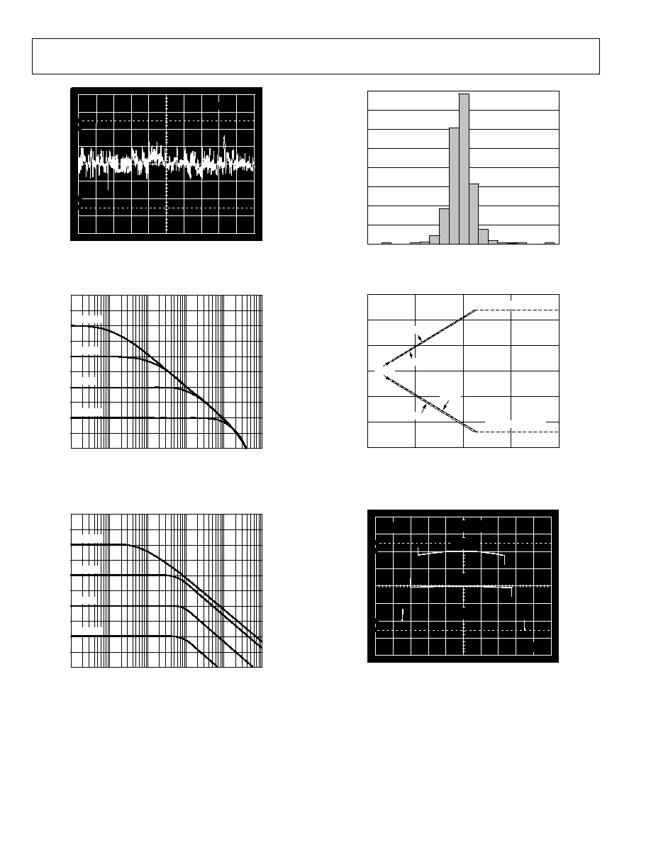
Figure 11. 0.1 Hz to 10 Hz Voltage Noise, RTI
40
30
20
10
0
10
20
30
40
50
60
GAIN (
d
B)
100
1k
10k
100k
1M
10M
FREQUENCY (Hz)
02992-C-012
G = +100
G = +10
G = +1
G = +0.1
Figure 12. Small Signal Frequency Response,
V
OUT
= 200 mV p-p, G = +0.1, +1, +10, and +100
40
30
20
10
0
10
20
30
40
50
60
GAIN (
d
B)
10
100
1k
10k
100k
1M
FREQUENCY (Hz)
02992-C-013
G = +100
G = +10
G = +1
G = +0.1
Figure 13. Large Signal Frequency Response,
V
OUT
= 20 V p-p, G = +0.1, +1, +10, and +100
0
5
10
15
20
25
% OF DE
V
I
CE
S
30
35
40
0
1
2
3
4
5
6
7
8
9
10
GAIN ERROR (ppm)
02992-C-014
9638 UNITS
Figure 14. Typical Distribution of +1 Gain Error
150
100
50
0
50
100
150
COM
M
ON-
M
ODE VOLTAGE (
V
)
V
S
(±V)
5
0
10
15
02992-C-015
20
UPPER CMV LIMIT
LOWER CMV LIMIT
V
REF
= 0V
+85°C
40°C
+85°C
40°C
+25°C
Figure 15. Common-Mode Operating Range vs.
Power Supply Voltage for Three Temperatures
02992-C-016
100
90
10
0
500
V
4.0V
R
L
= 1k
R
L
= 2k
R
L
= 10k
V
S
= ±15V
OUTPUT VOLTAGE (V)
OUTP
UT E
RROR (
V)
Figure 16. Normalized Gain Error vs. V
OUT
, V
S
= ±15 V
AD628
Rev. F | Page 11 of 20
02992-C-017
100
90
10
0
100
V
500mV
R
L
= 1k
R
L
= 2k
R
L
= 10k
V
S
= ±2.5V
OUTPUT VOLTAGE (V)
OUTP
UT E
RROR (
V)
Figure 17. Normalized Gain Error vs. V
OUT
, V
S
= ±2.5 V
BIAS
CURRE
NT (nA)
0
1
2
3
4
40
20
0
20
40
60
80
100
TEMPERATURE (°C)
02992-C-018
Figure 18. Bias Current vs. Temperature Buffer
15
10
5
0
5
10
15
OU
TPU
T
VOLTA
GE SW
IN
G (
V
)
0
5
10
15
20
25
OUTPUT CURRENT (mA)
02992-C-019
25°C
+85°C
25°C
40°C
+25°C
40°C
+85°C
+25°C
Figure 19. Output Voltage Operating Range vs. Output Current
02992-C-020
100
90
10
0
500mV
50mV
4
s
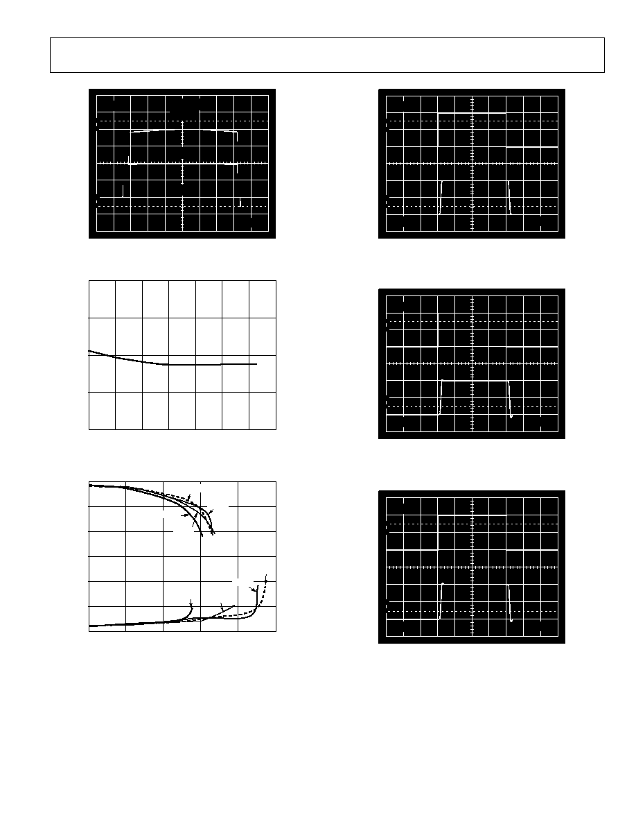
Figure 20. Small Signal Pulse Response,
R
L
= 2 k, C
L
= 0 pF, Top: Input, Bottom: Output
02992-C-021
100
90
10
0
500mV
50mV
4
s
Figure 21. Small Signal Pulse Response,
R
L
= 2 k, C
L
= 1000 pF, Top: Input, Bottom: Output
02992-C-021
100
90
10
0
500mV
50mV
4
s
Figure 22. Large Signal Pulse Response,
R
L
= 2 k, C
L
= 1000 pF, Top: Input, Bottom: Output
AD628
Rev. F | Page 12 of 20
02992-C-023
100
90
10
0
5V
10mV
100
s
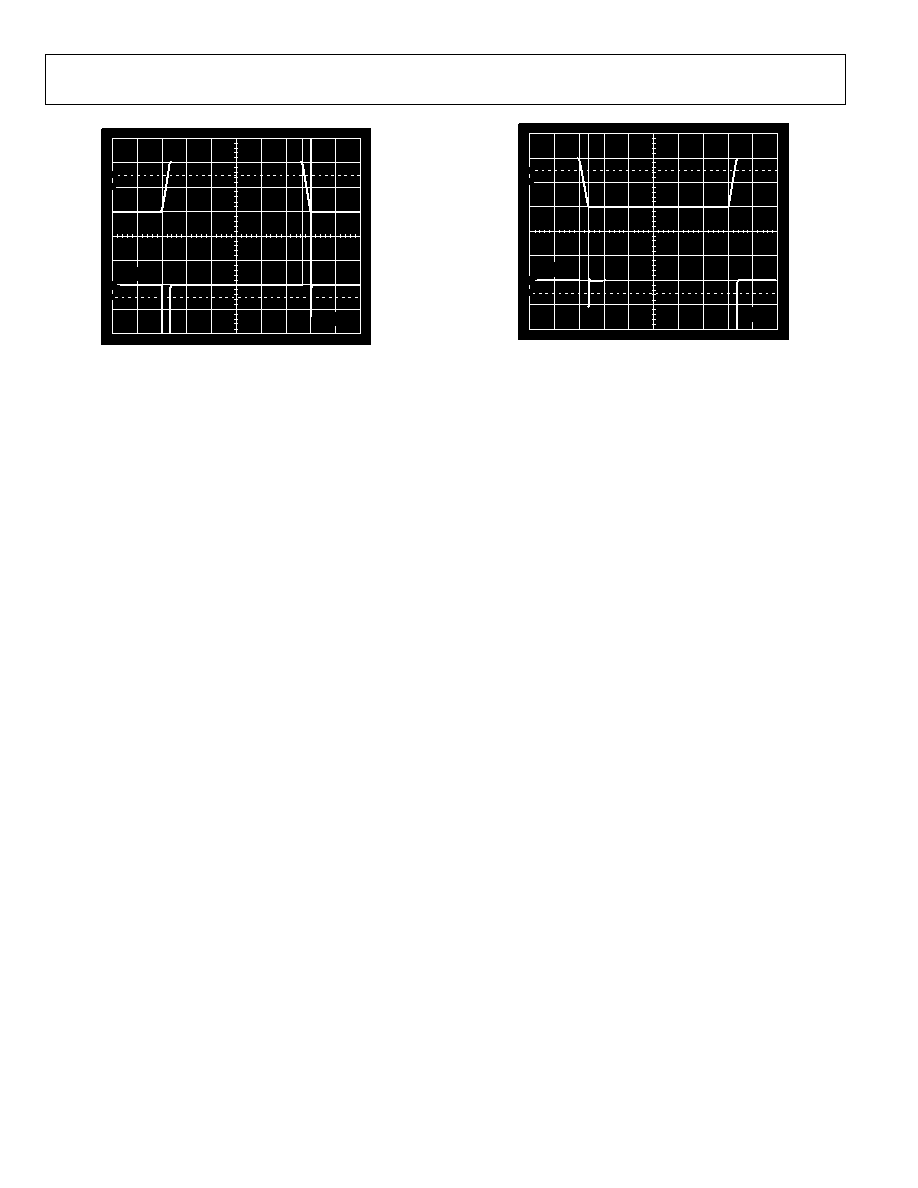
Figure 23. Settling Time to 0.01%, 0 V to 10 V Step
02992-C-024
100
90
10
0
5V
10mV
100
s
Figure 24. Settling Time to 0.01% 0 V to -10 V Step
AD628
Rev. F | Page 13 of 20
TEST CIRCUITS
+IN
IN
OUT
+
AD829
G = +100
+IN
IN
G = +0.1
+
AD707
IN
+IN
100k
FET
PROBE
HP3589A
SPECTRUM ANALYZER
C
FILT
V
S
V
REF
100k
R
G
10k
10k
10k
AD628
+V
S
02992-C
-
025
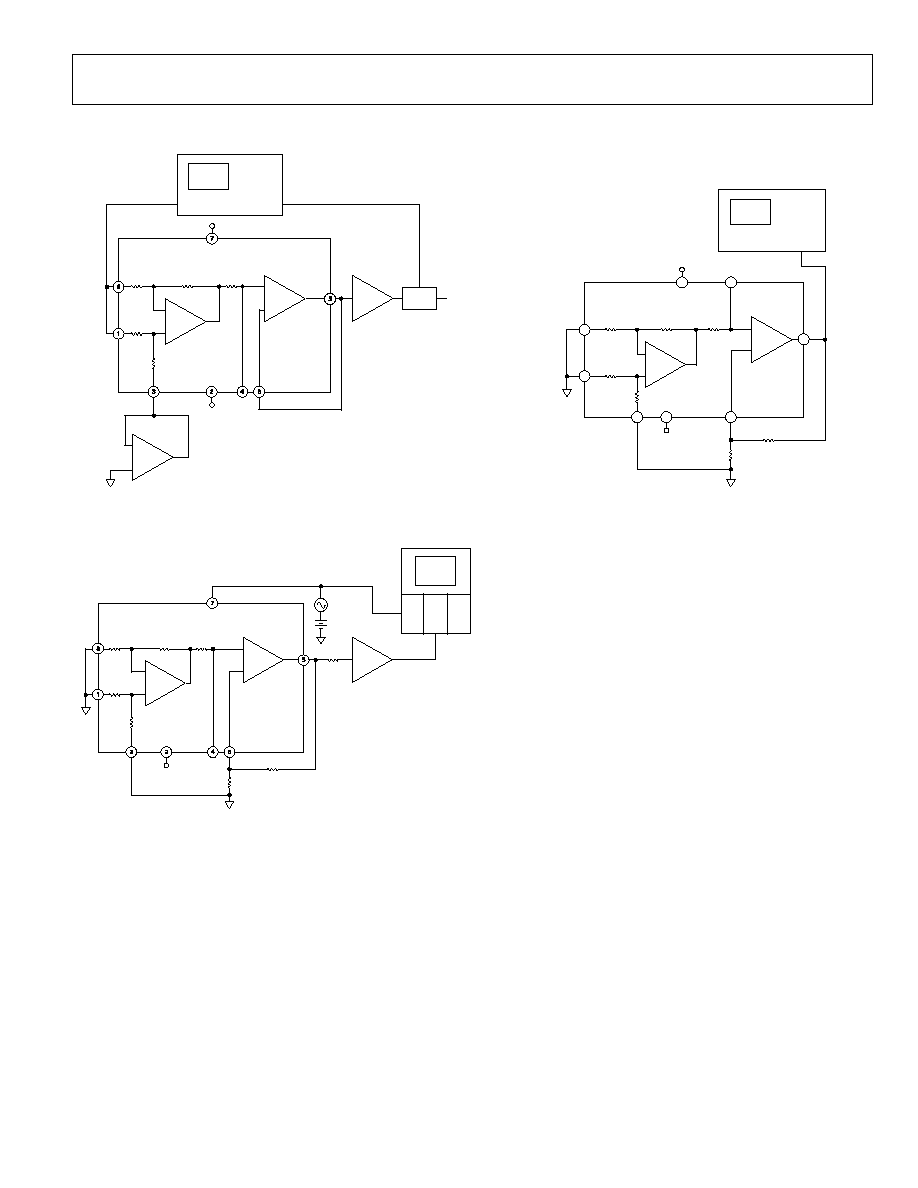
Figure 25. CMRR vs. Frequency
+IN
100k
C
FILT
V
REF
AD628
+V
S
+IN
IN
OUT
V
S
R
G
+
AD829
+IN
IN
G = +0.1
G = +100
G = +100
SCOPE
10k
IN
100k
10k
10k
20
+15V
1 VAC
02992-
C
-
026
Figure 26. PSRR vs. Frequency
6
2
3
1
8
7
5
4
+IN
100k
C
FILT
V
REF
10k
AD628
+V
S
HP3561A
SPECTRUM ANALYZER
10k
10k
+IN
IN
G = +0.1
+IN
IN
IN
100k
10k
10k
OUT
V
S
R
G
02992-C
-027
Figure 27. Noise Tests
AD628
Rev. F | Page 14 of 20
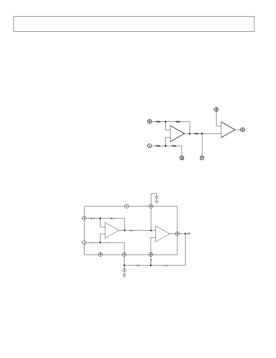
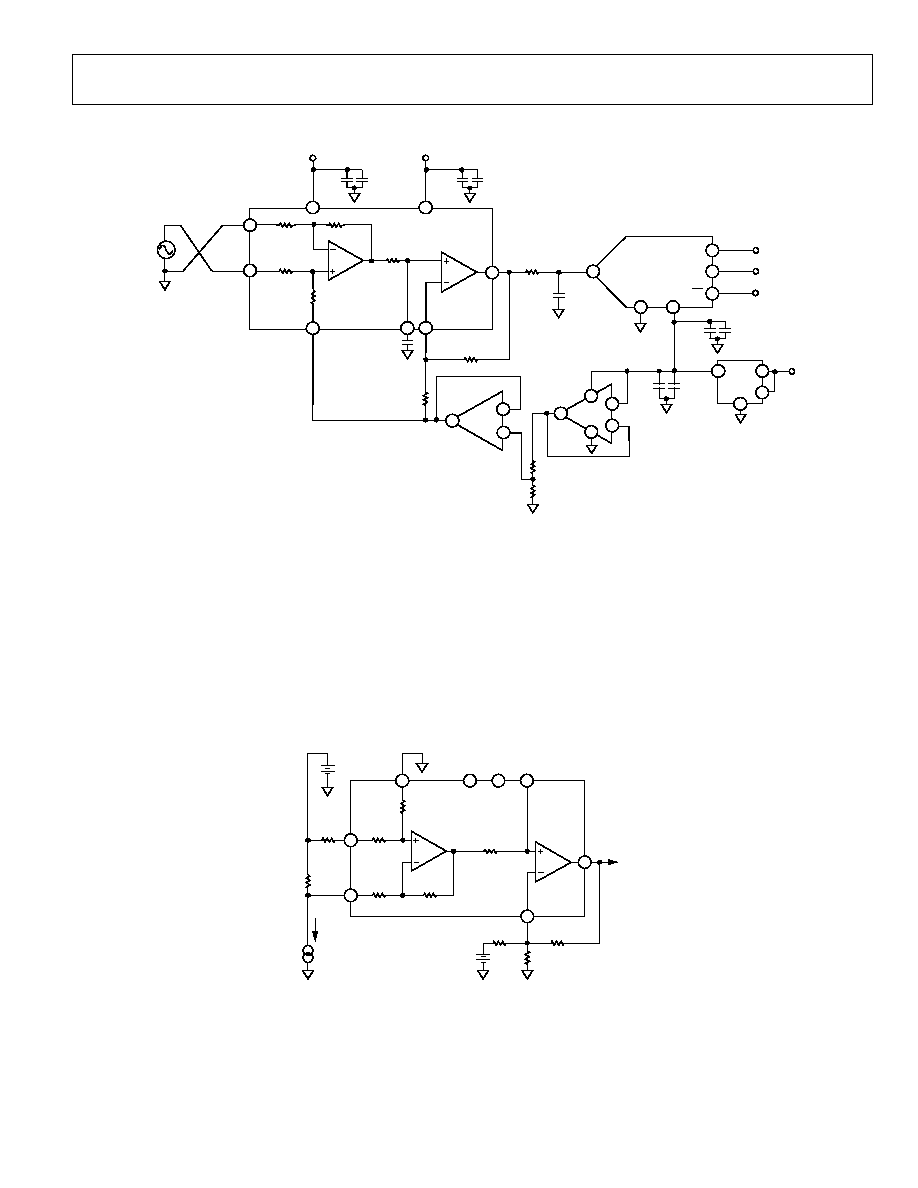
THEORY OF OPERATION
The AD628 is a high common-mode voltage difference
amplifier, combined with a user-configurable output amplifier
(see Figure 28 and Figure 29). Differential mode voltages in
excess of 120 V are accurately scaled by a precision 11:1 voltage
divider at the input. A reference voltage input is available to the
user at Pin 3 (V
REF
). The output common-mode voltage of the
difference amplifier is the same as the voltage applied to the
reference pin. If the uncommitted amplifier is configured for
gain, connect Pin 3 to one end of the external gain resistor to
establish the output common-mode voltage at Pin 5 (OUT).
The output of the difference amplifier is internally connected
to a 10 k resistor trimmed to better than ±0.1% absolute
accuracy. The resistor is connected to the noninverting input of
the output amplifier and is accessible at Pin 4 (C
FILT
). A
capacitor can be connected to implement a low-pass filter, a
resistor can be connected to further reduce the output voltage,
or a clamp circuit can be connected to limit the output swing.
The uncommitted amplifier is a high open-loop gain, low offset,
low drift op amp, with its noninverting input connected to the
internal 10 k resistor. Both inputs are accessible to the user.
Careful layout design has resulted in exceptional common-
mode rejection at higher frequencies. The inputs are connected
to Pin 1 (+IN) and Pin 8 (-IN), which are adjacent to the power
pins, Pin 2 (-V
S
) and Pin 7 (+V
S
). Because the power pins are at
ac ground, input impedance balance and, therefore, common-
mode rejection are preserved at higher frequencies.
+IN
IN
+IN
IN
A2
A1
+IN
IN
100k
100k
10k
10k
V
REF
10k
OUT
G = +0.1
C
FILT
R
G
02992-C-028
Figure 28. Simplified Schematic
+V
S
+IN
IN
V
S
A2
+IN
IN
100k
100k
10k
10k
V
REF
REFERENCE
VOLTAGE
10k
AD628
OUT
G = +0.1
R
G
R
EXT3
C
FILT
R
EXT2
R
EXT1
+IN
IN
A1
02992-C-029
Figure 29. Circuit Connections
AD628
Rev. F | Page 15 of 20
APPLICATIONS
GAIN ADJUSTMENT
The AD628 system gain is provided by an architecture
consisting of two amplifiers. The gain of the input stage
is fixed at 0.1; the output buffer is user-adjustable as
G
A2
= 1 + R
EXT1
/R
EXT2
. The system gain is then
+
×
=
EXT2
EXT1
TOTAL
R
R
G
1
0.1
(1)
At a 2 nA maximum, the input bias current of the buffer amplifier
is very low and any offset voltage induced at the buffer amplifier
by its bias current may be neglected (2 nA × 10 k = 20 V).
However, to absolutely minimize bias current effects, select R
EXT1
and R
EXT2
so that their parallel combination is 10 k. If practical
resistor values force the parallel combination of R
EXT1
and R
EXT2
below 10 k, add a series resistor (R
EXT3
) to make up for the
difference. Table 5 lists several values of gain and corresponding
resistor values.
Table 5. Nearest Standard 1% Resistor Values for
Various Gains
1
Total Gain
(V/V)
A2 Gain
(V/V)
R
EXT1
()
R
EXT2
()
R
EXT3
()
0.1 1 10
k
0
0.2
2
20 k
20 k
0
0.25
2.5
25.9 k
18.7 k
0
0.5
5
49.9 k
12.4 k
0
1
10
100 k
11 k
0
2
20
200 k
10.5 k
0
5
50
499 k
10.2 k
0
10
100
1 M
10.2 k
0
1
See
Figure 29
.
To set the system gain to less than 0.1, create an attenuator by
placing Resistor R
EXT4
from Pin 4 (C
FILT
) to the reference voltage.
A divider is formed by the 10 k resistor that is in series with
the positive input of A2 and Resistor R
EXT4
. A2 is configured for
unity gain.
Using a divider and setting A2 to unity gain yields
1
×
+
×
=
EXT4
EXT4
DIVIDER
W
R
R
G
k
10
0.1
/
INPUT VOLTAGE RANGE
VREF and the supply voltage determine the common-mode
input voltage range. The relation is expressed by
REF
S
CM
V
V
V
UPPER
10
2
1
11
-
+
)
V
.
(
(2)
REF
S
CM
V
V
10
2
1
11
-
+
-
)
V
.
(
V
LOWER
where V
S+
is the positive supply, V
S-
is the negative supply,
and 1.2 V is the headroom needed for suitable performance.
Equation 2 provides a general formula for calculating the
common-mode input voltage range. However, keep the AD628
within the maximum limits listed in Table 1 to maintain
optimal performance. This is illustrated in Figure 30 where the
maximum common-mode input voltage is limited to ±120 V.
Figure 31 shows the common-mode input voltage bounds for
single-supply voltages.
200
150
100
50
0
50
IN
PU
T C
OM
M
ON
-
M
OD
E VOLTA
GE (
V
)
100
150
200
8
6
2
4
0
10
12
1
SUPPLY VOLTAGE (±V)
02992-C-035
4
16
MAXIMUM INPUT COMMON-MODE
VOLTAGE WHEN V
REF
= GND
Figure 30. Input Common-Mode Voltage vs. Supply Voltage
for Dual Supplies
80
60
40
20
0
20
40
60
80
100
IN
PU
T C
OM
M
ON
-
M
OD
E VOLTA
GE (
V
)
8
6
2
4
0
10
12
1
SINGLE-SUPPLY VOLTAGE (V)
02992-C-034
4
16
MAXIMUM INPUT COMMON-MODE
VOLTAGE WHEN V
REF
= MIDSUPPLY
Figure 31. Input Common-Mode Voltage vs.
Supply Voltage for Single Supplies
AD628
Rev. F | Page 16 of 20
The differential input voltage range is constrained to the linear
operation of the internal amplifiers A1 and A2. The voltage
applied to the inputs of A1 and A2 should be between
V
S-
+ 1.2 V and V
S+
- 1.2 V. Similarly, the outputs of A1 and A2
should be kept between V
S-
+ 0.9 V and V
S+
- 0.9 V.
VOLTAGE LEVEL CONVERSION
Industrial signal conditioning and control applications typically
require connections between remote sensors or amplifiers and
centrally located control modules. Signal conditioners provide
output voltages of up to ±10 V full scale. However, ADCs or
microprocessors operating on single 3.3 V to 5 V logic supplies
are now the norm. Thus, the controller voltages require further
reduction in amplitude and reference.
Furthermore, voltage potentials between locations are seldom
compatible, and power line peaks and surges can generate
destructive energy between utility grids. The AD628 offers an
ideal solution to both problems. It attenuates otherwise destruc-
tive signal voltage peaks and surges by a factor of 10 and shifts
the differential input signal to the desired output voltage.
Conversion from voltage-driven or current-loop systems is
easily accomplished using the circuit shown in Figure 32. This
shows a circuit for converting inputs of various polarities and
amplitudes to the input of a single-supply ADC.
To adjust common-mode output voltage, connect Pin 3 (V
REF
)
and the lower end of the 10 k resistor to the desired voltage.
The output common-mode voltage is the same as the reference
voltage.
Designing such an application can be done in a few simple
steps, including the following:
·
Determine the required gain. For example, if the input
voltage must be transformed from ±10 V to 0 V to +5 V,
the gain is +5/+20 or +0.25.
·
Determine if the circuit common-mode voltage should be
changed. An AD7940 ADC is illustrated for this example.
When operating from a 5 V supply, the common-mode
voltage of the AD7940 is half the supply, or 2.5 V. If the
AD628 reference pin and the lower terminal of the 10 k
resistor are connected to a 2.5 V voltage source, the output
common-mode voltage is 2.5 V.
Table 6 shows resistor and reference values for commonly used
single-supply converter voltages. R
EXT3
is included as an option
to balance the source impedance into A2. This is described in
more detail in the Gain Adjustment section.
Table 6. Nearest 1% Resistor Values for Voltage Level
Conversion Applications
Input
Voltage (V)
ADC
Supply
Voltage (V)
Desired
Output
Voltage (V)
V
REF
(V)
R
EXT1
(k)
R
EXT2
(k)
±10 5
2.5
2.5
15
10
±5 5 2.5 2.5
39.7
10
10 5 2.5 0
39.7
10
5 5 2.5 0
89.8
10
±10 3
1.25 1.25
2.49
10
±5 3 1.25 1.25
15
10
10 3 1.25 0
15
10
5 3 1.25
0
39.7
10
AD628
Rev. F | Page 17 of 20
5
1
3
4
8
2
7
+Vs
Vs
6
IN
+IN
V
REF
100k
10k
100k
10k
10k
A1
A2
4
5
6
3
1
2
SCLK
SDATA
CS
GND
VDD
V
IN
AD628
SERIAL DATA
REF195
+12V
V
OUT
V
IN
2
3
4
6
C
FILT
R
G
10F
0.1F
10F
0.1F
10F
0.1F
10F
0.1F
AD7940
+/10V
15nF
2
3
1 AD8606
1/2
49.9
33nF
+12V
12V
10k
10k
AD628 REFERENCE VOLTAGE
R
EXT2
10k
R
EXT1
15k
AD8606
2/2
5
6
7
4
8
02
99
2-
03
0
Figure 32. Level Shifter
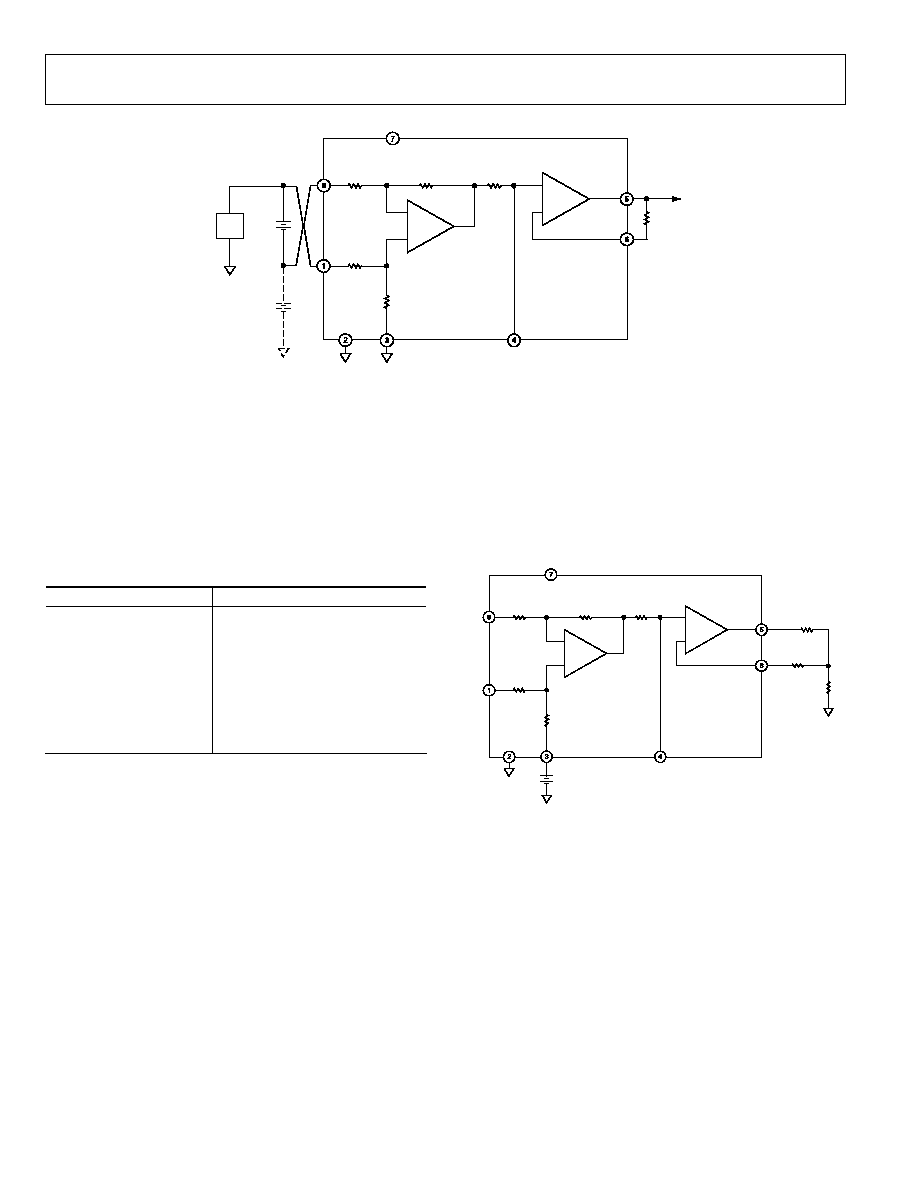
CURRENT LOOP RECEIVER
Analog data transmitted on a 4 to 20 mA current loop can be
detected with the receiver shown in Figure 33. The AD628 is an
ideal choice for such a function because the current loop is
driven with a compliance voltage sufficient to stabilize the loop,
and the resultant common-mode voltage often exceeds com-
monly used supply voltages. Note that with large shunt values, a
resistance of equal value must be inserted in series with the
inverting input to compensate for an error at the noninverting
input.
MONITORING BATTERY VOLTAGES
Figure 34 illustrates how the AD628 is used to monitor a battery
charger. Voltages approximately eight times the power supply
voltage can be applied to the input with no damage. The resistor
divider action is well-suited for the measurement of many
power supply applications, such as those found in battery
chargers or similar equipment.
6
8
1
4
5
7
2
3
AD628
+15V
+2.5V
9.53k
15V
10k
0V TO 5V
TO ADC
I = 4 TO 20mA
100k
210k
100k
100k
249
V
CM
= 15V
10k
10k
249
02
99
2-
C
-
03
1
Figure 33. Level Shifter for 4 to 20 mA Current Loop
AD628
Rev. F | Page 18 of 20
+IN
IN
G = +0.1
10k
A1
IN
100k
+V
S
5V
V
REF
V
S
+IN
IN
A2
OUT
AD628
100k
10k
OTHER
BATTERIES IN
CHARGING
CIRCUIT
CHARGING
CIRCUIT
+1.5V
BATTERY
10k
+IN
nV
BAT
(V)
R
EXT1
10k
0V TO 5V
TO ADC
C
FILT
R
G
02992-C-032
Figure 34. Battery Voltage Monitor
FILTER CAPACITOR VALUES
Connect a capacitor to Pin 4 (C
FILT
) to implement a low-pass
filter. The capacitor value is
( )
F
15.9/
t
f
C =
where f
t
is the desired 3 dB filter frequency.
Table 7 shows several frequencies and their closest standard
capacitor values.
Table 7. Capacitor Values for Various Filter Frequencies
Frequency (Hz)
Capacitor Value (F)
10
1.5
50
0.33
60
0.27
100
0.15
400
0.039
1 k
0.015
5 k
0.0033
10 k
0.0015
KELVIN CONNECTION
In certain applications, it may be desirable to connect the
inverting input of an amplifier to a remote reference point.
This eliminates errors resulting in circuit losses in interconnect-
ing wiring. The AD628 is particularly suited for this type of
connection. In Figure 35, a 10 k resistor added in the feedback
matches the source impedance of A2. This is described in more
detail in the Gain Adjustment section.
+IN
IN
A2
+V
S
5V
IN
+IN
V
REF
OUT
CIRCUIT
LOSS
LOAD
+IN
IN
G = +0.1
A1
AD628
V
S
10k
10k
10k
100k
100k
V
S
/2
C
FILT
R
G
10k
02992-
C-
033
Figure 35. Kelvin Connection
AD628
Rev. F | Page 19 of 20
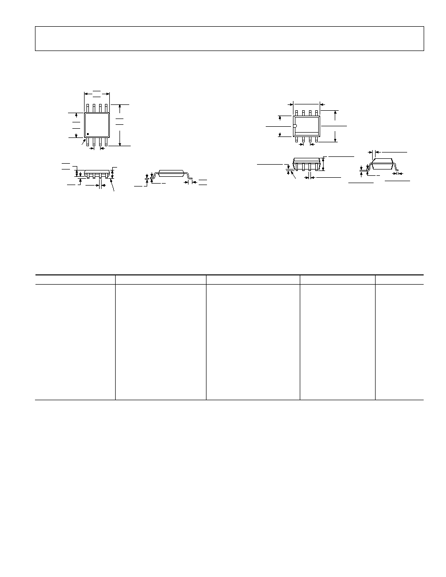
OUTLINE DIMENSIONS
COMPLIANT TO JEDEC STANDARDS MO-187-AA
0.80
0.60
0.40
8°
0°
4
8
1
5
PIN 1
0.65 BSC
SEATING
PLANE
0.38
0.22
1.10 MAX
3.20
3.00
2.80
COPLANARITY
0.10
0.23
0.08
3.20
3.00
2.80
5.15
4.90
4.65
0.15
0.00
0.95
0.85
0.75
Figure 36. 8-Lead Mini Small Outline Package [MSOP]
(RM-8)
Dimensions shown in millimeters
0.25 (0.0098)
0.17 (0.0067)
1.27 (0.0500)
0.40 (0.0157)
0.50 (0.0196)
0.25 (0.0099)
× 45°
8°
0°
1.75 (0.0688)
1.35 (0.0532)
SEATING
PLANE
0.25 (0.0098)
0.10 (0.0040)
4
1
8
5
5.00 (0.1968)
4.80 (0.1890)
4.00 (0.1574)
3.80 (0.1497)
1.27 (0.0500)
BSC
6.20 (0.2440)
5.80 (0.2284)
0.51 (0.0201)
0.31 (0.0122)
COPLANARITY
0.10
CONTROLLING DIMENSIONS ARE IN MILLIMETERS; INCH DIMENSIONS
(IN PARENTHESES) ARE ROUNDED-OFF MILLIMETER EQUIVALENTS FOR
REFERENCE ONLY AND ARE NOT APPROPRIATE FOR USE IN DESIGN.
COMPLIANT TO JEDEC STANDARDS MS-012-AA
Figure 37. 8-Lead Standard Small Outline Package [SOIC_N]
Narrow Body
(R-8)
Dimensions shown in millimeters and (inches)
ORDERING GUIDE
Model
Temperature Range
Description
Package Option
Branding
AD628AR
-40°C to +85°C
8-Lead SOIC_N
R-8
AD628AR-REEL
-40°C to +85°C
8-Lead SOIC_N 13" Reel
R-8
AD628AR-REEL7
-40°C to +85°C
8-Lead SOIC_N 7" Reel
R-8
AD628ARZ
1
-40°C to +85°C
8-Lead SOIC_N
R-8
AD628ARZ-RL
1
-40°C to +85°C
8-Lead SOIC_N 13" Reel
R-8
AD628ARZ-R7
1
-40°C to +85°C
8-Lead SOIC_N 7" Reel
R-8
AD628ARM
-40°C to +85°C
8-Lead MSOP
RM-8
JGA
AD628ARM-REEL
-40°C to +85°C
8-Lead MSOP 13" Reel
RM-8
JGA
AD628ARM-REEL7
-40°C to +85°C
8-Lead MSOP 7" Reel
RM-8
JGA
AD628ARMZ
1
-40°C to +85°C
8-Lead MSOP
RM-8
JGZ
AD628ARMZ-RL
1
-40°C to +85°C
8-Lead MSOP 13" Reel
RM-8
JGZ
AD628ARMZ-R7
1
-40°C to +85°C
8-Lead MSOP 7" Reel
RM-8
JGZ
AD628-EVAL
Evaluation
Board
1
Z = Pb-free part.

AD628
Rev. F | Page 20 of 20
T
NOTES
©2006 Analog Devices, Inc. All rights reserved. Trademarks and
registered trademarks are the property of their respective owners.
C02992-0-3/06(F)
TTT
Document Outline