Äîêóìåíòàöèÿ è îïèñàíèÿ www.docs.chipfind.ru
One Technology Way, P.O. Box 9106, Norwood. MA 02062-9106, U.S.A.
Tel: 617/329-4700
Fax: 617/326-8703
REV. 0
Information furnished by Analog Devices is believed to be accurate and
reliable. However, no responsibility is assumed by Analog Devices for its
use, nor for any infringements of patents or other rights of third parties
which may result from its use. No license is granted by implication or
otherwise under any patent or patent rights of Analog Devices.
=
AD73360(L) Evaluation Board,
Six Input Channel Analog Front End
EVAL-AD73360(L)EB
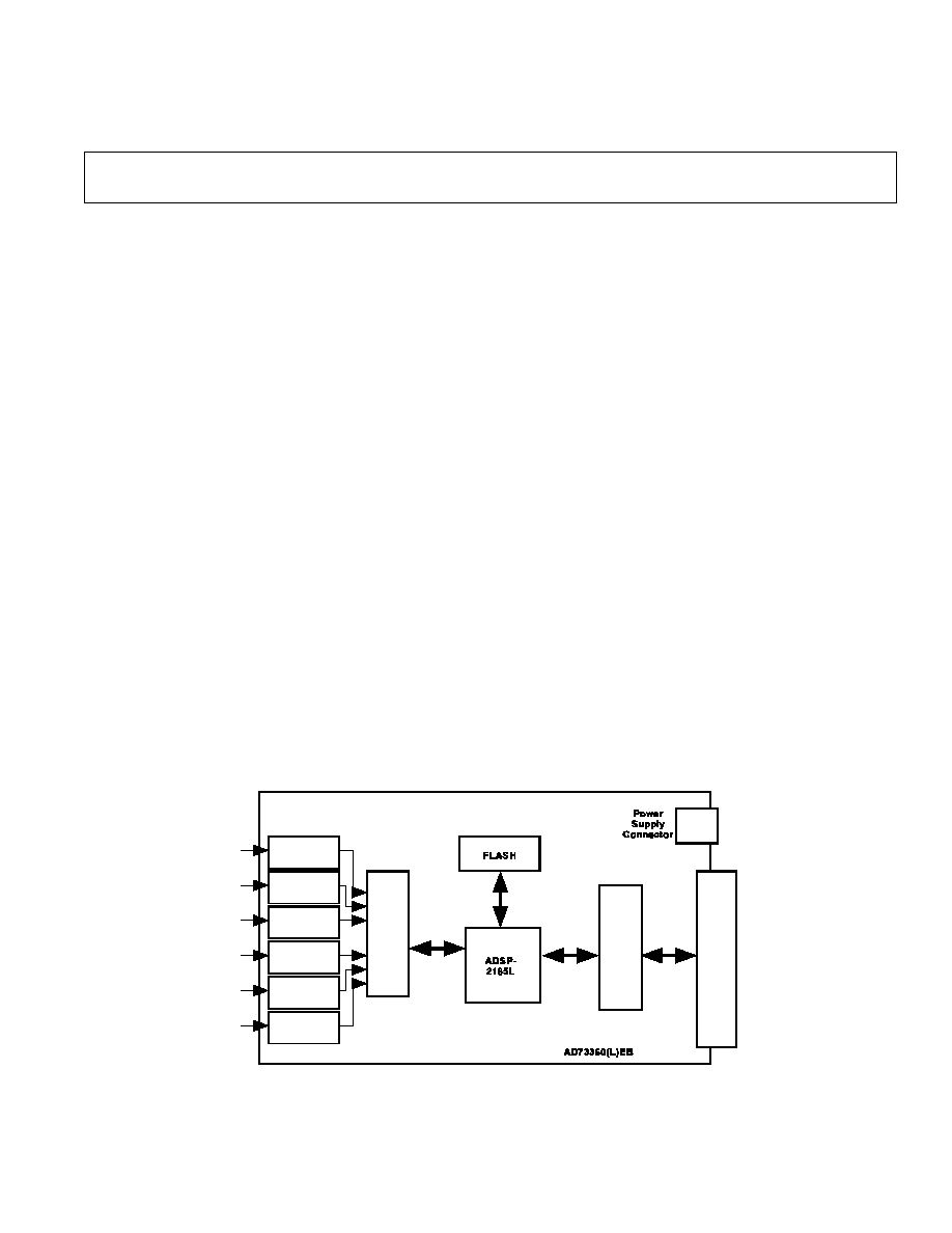
FUNCTIONAL BLOCK DIAGRAM
FEATURES
Full-Featured Evaluation Board for the
AD73360 & AD73360L
Stand Alone Operation
On-Board DSP
High-Speed Parallel Interface to the PC
PC Software for Control and Data Analysis.
I N T R O D U C T I O N
This Technical Note describes the evaluation board for
the both AD73360 and the AD73360L six input-channel
simultaneous sampling sigma-delta A/D converters. The
AD73360L is a 3V only version of the AD73360. Full
data on the both parts is available in the relevant data
sheet available from Analog Devices and should be con-
sulted in conjunction with this Technical Note when using
the Evaluation Board.
The evaluation board allows a user to exercise all the
functions of the AD73360(L). The analog inputs are buff-
ered by op-amps which may be configured for ac- or dc-
coupling operation. The evaluation board contains an
ADSP2185L digital signal processor which can be pro-
grammed to control and read data from the AD73360(L).
The evaluation board comes with software which can be
run on the users PC allowing programs to be downloaded
and data to be uploaded from the evaluation board. Sev-
eral example programs are provided which demoonstrate
the capabilities of the AD73360(L).
SETTING UP THE EVALUATION BOARD FOR THE
FIRST TIME
The AD73360(L) evaluation board kit comes with the
evaluation board for the required part, AD73360 or
AD73360L and software which allows the user to program
the AD73360(L) and read back samples using a PC. The
software is provide on a CD ROM and this also contains a
data sheet, this technical note and some DSP example
code. The user needs to supply a Centronics printer port
cable and a 6V to 12V DC power supply.
Installing the Software
When the CD ROM is inserted into the PCs drive the
install routine automatically starts. This allows the user to
select which components to install i.e. data sheet, techni-
cal note, application software etc. When using the software
to control the evaluation board it is important the follow-
ing steps are completed in order.
1. The evaluation board should be powered up with the
printer port cable disconnected.
2. The software should be loaded.
3. The printer port cable can then be connected and the
PC should be able to communicate with the evaluation
board.
S ig n a l
C o nd itio n in g
S ig n a l
C o nd itio n in g
S ig n a l
C o nd itio n in g
S ig n a l
C o nd itio n in g
S ig n a l
C o nd itio n in g
S ig n a l
C o nd itio n in g
AD
7
336
0(
L
)
Co
n
t
ro
l
Logi
c
Pr
i
n
t
e
r P
o
r
t
Co
n
ne
c
to
r
An
al
o
g
In
p
ut
s
EVAL-AD73360(L)EB
2
REV. 0
System Requirements
Pentium 90 IBM Compatible PC
Windows 95
4Mbytes Hard Disk Space
Bidirectional Printer Port (PS/2, EPP, ECP)
OPERATING THE AD73360(L) EVALUATION BOARD
Power Supply
The AD73360(L) evaluation board can be powered from
any +9 V to +12 V DC power supply connected to J10 on
the board. This supply is regulated to +5 V to power the
PC interface section of the board and also regulated to
+3.2 V to power the DSP and AD73360(L) sections. The
analog section of the AD73360 can also be powered from
+5 V if required. This should only be done when the
AD73360 is used in the evaluation board.
When power is applied the POWER LED D4 should be
lit indicating that the power connector is correctly polar-
ized. Also the LED connected to FL2 should begin to
flash on and off indicating that the DSP has booted from
the on-board flash EPROM correctly.
When the evaluation board has been powered up the PC
software can be loaded and the printer port connector can
be connected. the PC should now be able to communicate
with the evaluation board.
Link Settings
The AD73360(L) evaluation board has a number of link
options which can be used to select the various operating
conditions of the evaluation board. The linking options
are described in detail below.
Table I. Interface Mode Selection
Link
Position
Function
LK1
A
1
Frame-Sync Loop
Back
B
Non Frame-Sync
Loop Back
1 Default Link Position
Table II. Crystal Frequency Selection
LK2
LK3
LK4
Fout
I N
I N
I N
Fo/2
1
2
I N
I N
O U T
Fo/4
I N
O U T
I N
Fo/8
I N
O U T
O U T
Fo/16
O U T
I N
I N
Fo/32
O U T
I N
O U T
Fo/64
O U T
O U T
I N
Fo/128
O U T
O U T
O U T
Fo/256
1 Fo=16.384MHz
2 Default Link Positions
Table III. Master Clock Selection
Link
Position
MCLK Frequency
LK5
A
1
16.384MHz
B
Fout
1. Default Link Position
Tabel IV. Reference Selection
Link
Position
Function
LK6
IN
1
External Reference
O U T
Internal Reference
1. Default Link Position
Tabel V. Voltage Selection for AD73360(L)
Link
Position
Function
LK7
A
+5V Analog Section
B
1
+3V Analog Section
1. Default Link PositionEvaluation Board Software
EVALUATION BOARD SOFTWARE
The evaluation board comes with software which will al-
low the user to operate the various functions of the
AD73360(L). There are two main sections to the com-
plete software package. One runs on the PC and handles
all the communications between the PC and the evaluation
board. The PC software can be used to load a DSP based
program to the evaluation board which is specifically writ-
ten to operate the AD73360 in a required manner. The
second section of the software is the DSP programs.
These are loaded to the ADSP2185L on the evaluation
board. The programs are designed to allow the user to
gather data from the AD73360 and upload it from to the
PC to be saved or analysised. The DSP example programs
can be modified and recompiled to meet the needs of the
users end application if necessary.
PC Software Description
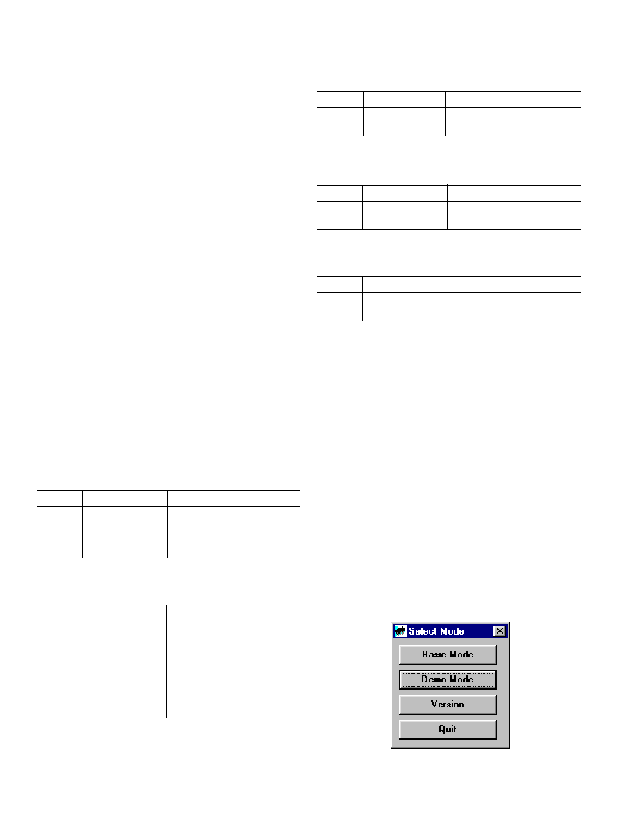
When the user runs the software they are presented with a
selection screen where the user can determine if they want
to use the Basic or Demonstration Mode options. The
Selection Screen is shown in Figure 1.
Figure 1. Selection Screen
EVAL-AD7360(L)EB
REV. 0
3
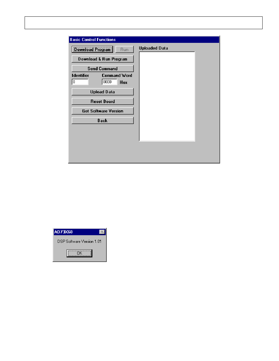
When running the software for the very first time it is
advisable to select the Basic screen as this will allow the
user to verify that the PC is communicating with the
evaluation board and vice versa. The Basic Screen is
shown in Figure 2. The user should click on the Get Soft-
ware Version button to establish if the communications are
working. If they are the user should see a message box
similar to that of Figure 3.
Figure 2. The Basic Mode Screen
Figure 3. Software Version Message Box
The additional functions available in this screen will be
described later in this document.
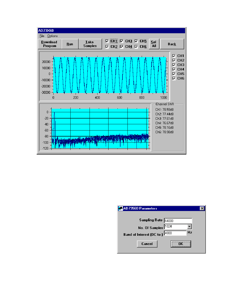
DEMONSTRATIONS SCREEN
The Demonstrations Screen will allow the user to select
one of a number of demonstration programs which will
program the AD73360(L) and read data from one or more
selected channels. Figure 4 shows the Demonstrantions
Screen.
Menu Item Descriptions
File Menu:
Save Data: The user can save the ADC samples taken
by the AD73360(L). The samples are saved to a text file
which can be opened by programs such as Notepad, Excel
or Mathcad for further examination/analysis.
Save FFT Data: The user can save the results of the
FFTs performed on the ADC data. The data is saved to a
text file which can be opened by programs such as
Notepad, Excel or Mathcad for further examination/analy-
sis.
Load Data: The user can reload previously saved data
into the program . The program will display the ADC
samples and recalculate the FFT for each channel.
Options Menu:
Run On Download: Selecting this option will automati-
cally run any program which is downloaded to the DSP. If
this option is deselected the Run button must be pressed in
order to start the DSP program.
AD73x60 Options: This option allows the user to select
the Sample Rate used by the DSP program, the number of
ADC samples to be taken by each channel and the Fre-
quency Band of Interest over which to calculate the SNR
for each channel.
AD73x60 Options: Selecting this option causes the
evaluation board to be reset.
Printer Port: This option allows the user to select which
printer port the software should use to communicate with
the evaluation board. By default LPT1 is chosen.
EVAL-AD73360(L)EB
4
REV. 0
Figure 4. The Demonstration Screen
Demonstration Programs
The demonstration programs provided with the
AD73360(L) evaluation board allow the user to program
the device and read data from one or more channels. The
samples are automatically uploaded and graphed once they
have been acquired. In addition a Fast Fourier Transform
(FFT) is performed and the Signal to Noise+Distortion
Ratio (SNR+D) is calculated for all selected channels.
The demonstration programs sample data at either 8KHz
or 64KHz. The DSP source code for each demonstration
program is included and can be modified and recompiled
if required
1
.
Running a Demonstration Program
With the evaluation board powered up and connected to
the PC the user can download the required program to the
evaluation board by pressing the Download Program
button. This will display a dialog box from which the user
can select the required program. When the OPEN button
is clicked the evaluation board is reset and the program is
downloaded. If the Run on Download option is not se-
lected the user must click the Run button to start the pro-
gram running. The user should ensure that the correct
sample rate is selected by clicking on the Options/AD73x60
Options menu item. The user also has the option to alter
the band of interest over which the SNR+D is calculated
and change the number of samples to take. Note that the
number of samples which can be taken is limited to the
amount of data memory available in the DSP and the
number of ADC channels selected. The number of
samples selected should not exceed 16000/N where N is
the number of ADC channels. Figure 5 shows the
AD73x60 options window.
Figure 5. The AD73x60 Options Window
1
Recompiling DSP source code requires the ADSP21xx assembler and linker
tools.
EVAL-AD7360(L)EB
REV. 0
5
When the DSP program is running the user can click
Take Samples. This will cause the the PC to send a com-
mand to the DSP on the evaluation board. The DSP will
bring the SE and RESET lines of the AD73360(L) high
and begin programming the device. The AD73360(L) is
configured in Frame-Sync Loop Back and is programmed
to operate in Data Mode. After allowing some time for the
reference to settle the AD73360(L) will store the required
number of samples to the data memory of the DSP. Once
completed the DSP will bring the RESET and SE of the
AD73360(L) low and begin uploading the data to the PC.
When the data has been transferred the PC will graph the
data and calculate the FFT. It should be noted that the
number of channels selected at the top of the demonstra-
tion window should match the number of ADC channels
powered up on the AD73360(L).
THE BASIC MODE SCREEN
The Basic Mode Screen as shown in Figure 2 allows the
user to download their own programs to the evaluation
board, send it commands and upload data memory for
saving or analysis.
Downloading Programs
The user has the option of downloading a program to the
evaluation board in one of two ways. The first is to down-
load the program but not to run it until the Run button is
clicked. The second is to download and automatically run
the program. If the user is using a modified version of the
BASIC.DSP program the LED on FL2 will flash a num-
ber of times to indicated that the program has been down-
loaded and run successfully.
Sending Commands
A command can be sent to the evaluation board which can
be used to determine which action is to be performed. The
command is made up of an Identifier Byte and a 16 bit
Control Word. The Identifier Byte is stored in data
memory location 0x3FDB and the Control Word is stored
in data memory location 0x3FDA. The BASIC.DSP pro-
gram will read the Identifier Byte and flash the LED that
number of times.
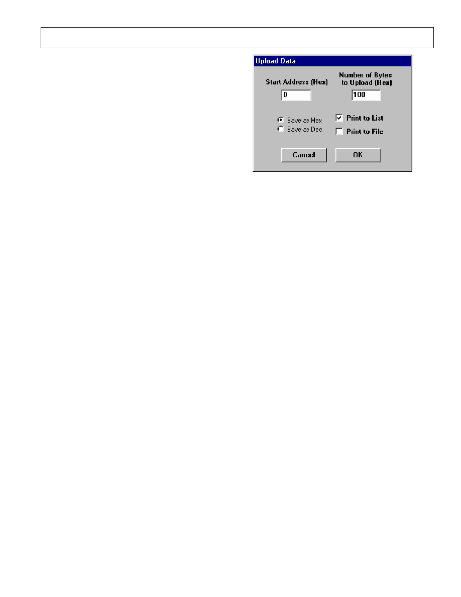
Uploading Data
If the user has acquired ADC data from the AD73360(L)
which is stored in data memory it can be uploaded to the
PC. Clicking the Upload Data button will display the
screen shown in Figure 6. The user can select the start
address and the number of words to upload. The uploaded
data can be saved to a file or to a list box on the Basic
Mode Screen. The user also has the option to save/display
the data in decimal or hexidecimal format.
Reset Board
This button allows the user to reset the evaluation board if
required.
Get Software Version
This button will read the version number of the boot pro-
gram which is store on the evaluation board. This is a
useful indication that the communication routines are fully
working as it involves 2-way communication to be suc-
cessful.
Figure 6. the Upload Data Screen
EVAL-AD73360(L)EB
6
REV. 0
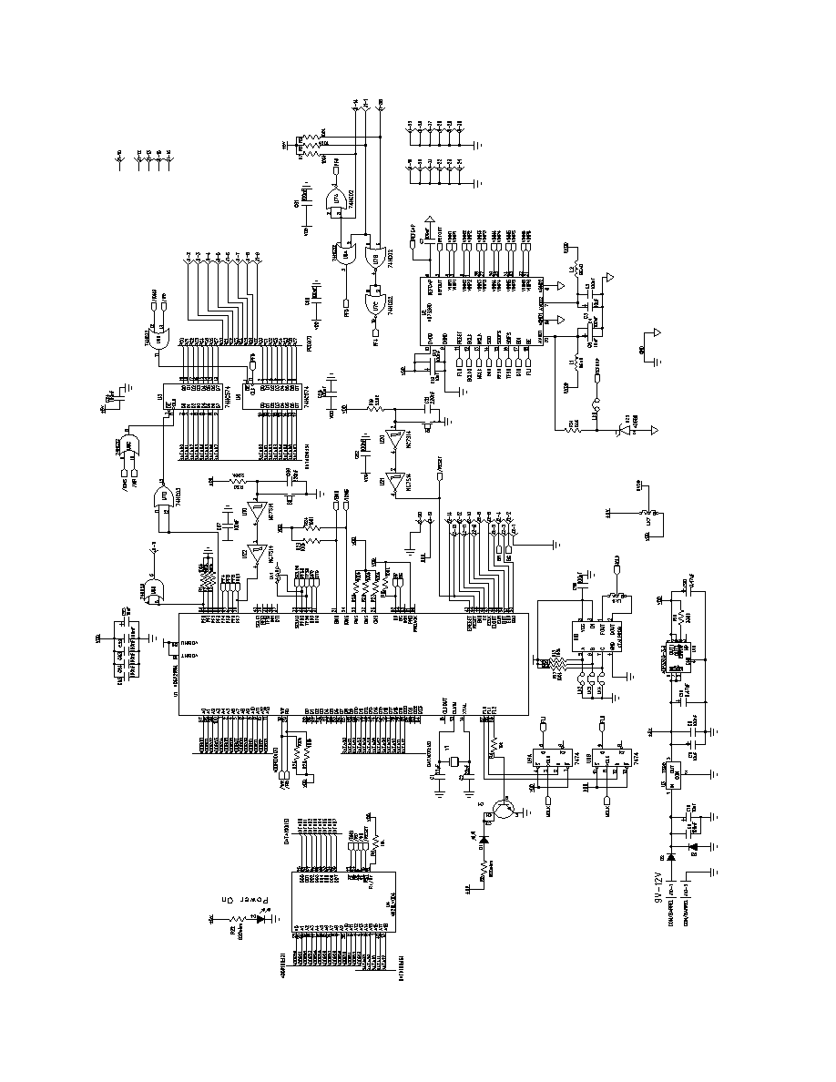
Figure 7. Evaluation Board Schematic
EVAL-AD7360(L)EB
REV. 0
7
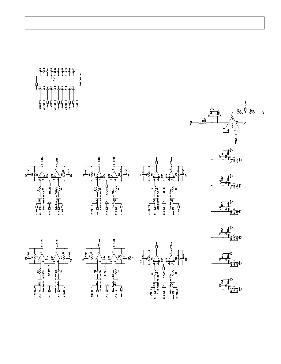
Figure 8. Evaluation Board Schematic (cont'd)

EVAL-AD73360(L)EB
8
REV. 0
Table VI. Troubleshooting guide
Symptom
Possible Cause
Both LEDs Off
No power is applied to the evaluation board. The evaluation board requires a +9V to
+12V DC supply.
Power LED On but
The DSP has not booted properly. Remove the printer port cable, if connected, and
FL2 LED not flashing
press the RESET button.
No Communication between
There are a number of possible causes for a communications failure. These are listed
PC and Evaluation Board.
below.
1. Cable not connected or incorrect cable type. The cable should be a fully-populated
Centronics printer port cable.
2. Incorrect printer port. The evaluation board requires that the printer port has bi-
directional capability. Acceptable types are PS/2, EPP and ECP.
3. Correct Printer Port but bidirectional capability not enabled. It is possible that a
bidirectional printer port can be set to be unidirectional mode in the PC BIOS.
The user should consult the PC manual for instructions on examining the BIOS
4. Incorrect Printer Port Address. There are three possible addresses for a printer
ports and the one fitted to a users PC may not be the same as the default address.
This can be changed using the Printer Port menu item.
Demonstration Programs
The AD73360(L) may not be acquiring samples. Verify that the correct link positions
Timeout
are selected. Also verify that the SE and RESET are being brought high and that the
the AD73360(L) is giving out the correct number of Frame Syncs per sample period
once it is in program mode.
Verify that the AD73360(L) is receiving an MCLK signal.

EVAL-AD7360(L)EB
REV. 0
9
Qty
Reference
Description/Part Name
1
U 1
ADSP2185LLKST-133
1
U 2
AD73360LAR or AD73360AR
1
U 3
LM7805CT
1
U 4
AM29LV004BB-90EC
1
U 5
74VHC57M
2
U 6
74LCX574WM
1
U 7
74LVX02M
1
U 8
74LVX32M
1
U 9
74LVX74M
4
U10 U20-22
NC7S14M5
6
U11-16
AD8062AR
1
U17
AD820AR
1
U18
16.384MHz Programmable Oscillator
1
U19
ADP3303AR-3.2
1
U23
AD589LH
17
R1-R3 R7-R10 R15-R17 R23-R29
100K
28
R4 R6 R11-R14 R20 R21 R35-R54
10K
2
R5 R22
820
1
R18
330K
2
R19 R30
220K
1
R31
5.6K
3
L1-3
SMD Inductor
13
C5 C6 C10-C12 C20 C23 C26 C28
10uF
C30 C32 C34 C36
2
C19 C20
0.47µF
2
C1 C2
22pF
25
C3 C4 C7-C9 C13 C16 C18 C22
0.1µF
C24-25 C27 C29 C31 C33 C35 C37
C60-C65 C67
12
C14 C15 C40 C41 C44 C45 C48
470pF
C49 C52 C53 C56 C57
2
C21 C66
220nF
12
C38 C39 C42 C43 C46 C47 C50
0
Res to be fitted
C51 C54 C55 C58 C59
1
J 1
Centronics Connector
1
J 2
20 Way IDC Header
6
J3-8
Pin Power Connector
1
J 9
26 PIN EDGE CONNECTOR
1
J10
BARREL CONNECTOR
3
LK1 LK5 LK7
JUMPER BLOCK USING 3 PIN SIP HEADER
4
LK2-4 LK6
JUMPER BLOCK, 2 PINS 0.1 SPACING"
7
LK1-7
Shorting Plug
D 1
3mm Red LED
2
D 4
3mm Green LED
2
D2-3
1N4001 Diode
1
Q 1
2N2222 SMD Transistor
2
S1-2
Push Button Switch (sealed 6mm x 6mm)
1
Y1
20MHz Crystal
Table Vii. Bill of Materials