Äîêóìåíòàöèÿ è îïèñàíèÿ www.docs.chipfind.ru

EVAL-ADM1028
=
REV. PrA 05/2000
Information furnished by Analog Devices is believed to be accurate and
reliable. However, no responsibility is assumed by Analog Devices for its
use, nor for any infringements of patents or other rights of third parties
which may result from its use. No license is granted by implication or
otherwise under any patent or patent rights of Analog Devices.
One Technology Way, P.O. Box 9106, Norwood, MA 02062-9106, U.S.A.
Tel: 781/329-4700
World Wide Web Site: http://www.analog.com
Fax: 781/326-8703
Analog Devices, Inc., 1998
Evaluation Board for PC Temperature
Monitor and Fan Control ASIC
FEATURES
On chip Temperature Sensor
External Temperature Measurement with Remote Diode
Interrupt and Overtemperature Outputs
Fault Tolerant Fan Control with Auto Hardware Trip Point
Remote Reset and Power Down Functions
LDCM Support
System Management Bus (SMBus) Communications
Standby Mode to Minimize Power Consumption
Limit Comparison of all Monitored Values
APPLICATIONS
Network Servers and Personal Computers
Microprocessor-Based Office Equipment
Test Equipment and Measuring Instruments
I N T R O D U C T I O N
The ADM1028 evaluation board allows the ADM1028
PC Temperature Monitor and Fan Control ASIC to be
quickly and easily evaluated using a personal computer.
Using the evaluation board and the accompanying
software the ADM1028 can be interfaced to any personal
computer running Windows
95 or Windows
98, via the
computers parallel port.
The evaluation board allows the input and output
functions of the ADM1028 to be exercised without the
need for external components. The software allows control
and monitoring of the ADM1028's internal registers.
THE ADM1028
The following is a brief description of the ADM1028 and
a system overview. Further information can be found on
the ADM1028 datasheet.
The ADM1028 is a low cost temperature monitor and fan
controller for microprocessor based systems. The device
can measure the temperature of a microprocessor using an
on-chip diode connected transistor or can use a low cost
small signal transistor.
Measured values can be read out via the SMBus and
values for limit comparisons can be programmed in over
the same serial bus.
The ADM1028 also contains a DAC for fan speed
control. An automatic hardware temperature trip point is
provided and the fan will be driven to full speed if it is
exceeded.
The chip also has remote reset and power down
functionality, allowing it to be remotely shut down via the
SMBus.
EVALUATION SYSTEM PACKAGE CONTENTS
The evaluation system contains the following items
1. The ADM1028 Evaluation Board
2. Centronics Cable
3. CD containing this application note, datasheet and the
ADM1028 evaluation software.
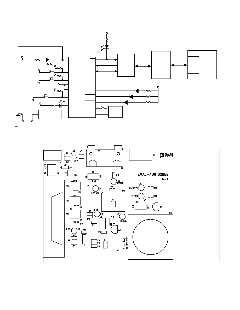
EVALUATION BOARD HARDWARE
The ADM1028 evaluation board contains the following
main components which can be identified from the block
diagram, printed circuit board silk screen and schematic
diagram of figures 1, 2 and 3 overleaf.
1. ADM1028 IC
2. NPN sensor transistor
3. LED indicators
4. Interface Buffers
5. Connector for parallel interface.
6. Test Connector for connecting to remote thermal
sensor (J4)
7. Fan.
EVAL-ADM1028
2
REV. PrA
Figure1. ADM1028 Evaluation Board Block Diagram
Figure2. ADM1028 Evaluation Board Silk Screen
V
D D
F AN _O F F
A D M 1 0 2 8
S DA T A
BU F FE R S
S CL K
IN T
V
D D
D6
RE D
IN T
36-W A Y
CE N T RO NIC S
CO N NE CT O R
(J1)*
PC
P
A
R
A
LLE
L
PO
R
T
R_O FF
T HE R M B
T HE R M A
V
D D
D3
RE D
R_O FF
D4, R E D
T HE R M B
D5, R E D
T HE R M A
D+
D-
NP N
S E NS O R
S 2
F AN _S P D
F an S p eed Sig n al
Co n d ition in g Blo ck
J6-1
J6- 2
J6 = Fan
Co n n ector
R_R S T
V
C C
RS T
P B3
V
C C
V
C C
V
C C
G ND
AU X RS T
P B2
G P I
P B1
V
C C
c
V
C C
V
C C
EVAL-ADM1028
3
REV. PrA
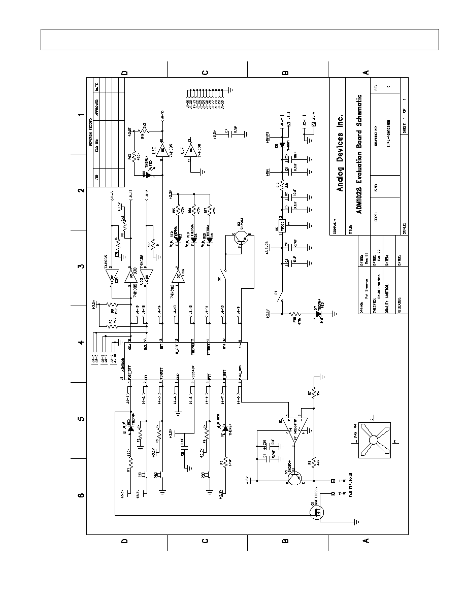
Figure3. ADM1028 Evaluation Board Schematic

EVAL-ADM1028
4
REV. PrA
CONNECTORS AND SWITCHES AND INDICATORS
The function of the various connectors, switches and
indicators on the evaluation board are explained below.
CENTRONICS CONNECTOR (J1)
The evaluation board may be connected to the personal
computer via the parallel printer port using the centronics
cable provided.
POWER CONNECTORS (J2 & J3)
Power is supplied to the board via J2 using a 15V Power
Supply mains adaptor. This adapor is not included in the
evaluation kit. Alternatively power may be supplied to the
board via J3 thus allowing a desktop power supply to be
used.
TEST CONNECTOR (J4)
J4 is provided as a test connector on the ADM1028
evaluation board. Each pin of the ADM1028 is connected
directly to the corresponding pin of the test connector thus
allowing the user easy access to all signals to and from the
ADM1028 (i.e. pin 1 of the ADM1028 is connected to
pin 1 of the test connector).
An off board thermal sensor may be connected as the
external sensor via pins 9 and 10 of the test connector.
SMBUS INTERFACE CONNECTOR (J5)
The SMBus interface connector allows the evaluation
board to be connected to the SMBus of a personal
computer using a DIMM interface card. To make this
connection it may be necessary to remove one of the
DIMM memory modules on the PC motherboard, if all
DIMM sockets are occupied. This will affect the BIOS
setup and Windows 95 and should only be attempted by a
competent user.
ON/OFF SWITCH (S1)
This is simply an on/off switch for the evaluation board.
REMOTE DIODE SWITCH (S2)
This switch allows the user to choose between the on-
board remote temperature sensor (Q3) and one that can be
connected to the test connector J4. When the switch is in
the on position the Q3 is selected. When it is in the off
position the off board sensor is selected.
FAN_OFF INDICATOR (D1)
When the FAN_OFF pin is asserted low this indicates a
request to switch off the fan regardless of the fan_spd
output. When this occurs the FAN_OFF LED will light.
When the pin is asserted high again the LED will switch
off immediately. The FAN_OFF pin is asserted low when
bit 5 of the configuration register is set to 0. This bit
defaults to 1 on power up.
R_RST INDICATOR (D2)
Writing a 1 to the R_RST Register of the Remote
Function Register causes the R_RST pin to be pulsed low
for a minimum of 125
µ
s. This bit will self clear to 0 when
the R_RST pulse is complete. As a result the LED will
only light for the duration of the pulse.
R_OFF INDICATOR (D3)
Writing a 1 to the R_OFF bit of the Remote Function
Register causes the R_OFF output to be driven high. This
in turn causes the R_OFF LED to light. This bit is
cleared only when RST is asserted, i.e. the LED will
remain lighting until the RST button (PB3) is pressed.
THERMA & THERMB INDICATORS (D4 & D5)
These LED's light when the THERM temperature limits
are exceeded for more than three consecutive
measurements. THERMA and THERMB are functionally
identical. THERMA has an internal pullup to 3.3V while
THERMB is open drain and can be pulled up to any
required voltage. See datasheet for more information.
The LED's will switch off when the temperature falls to
5°C below the THERM limit for three consecutive
measurements
INTERRUPT LED (D6)
This LED illuminates whenever the ADM1028 issues an
interrupt signal (eg.when an out of limit measurement is
made). For more information on the various conditions
which cause INT to be pulled low plesase see the
datasheet.
POWER LED (D7)
This LED will illuminate whenever power is supplied to
the board and S1 is in the ON condition.
GPI INPUT SWITCH(PB1)
This switch essentially allows the user to generate an out
of limit measurement for the GPI (General Purpose
Input). This should result in an INT being generated if
the GPI interrupt is not masked.
AUXRST SWITCH (PB2)
Pulling AUXRST low will reset the ADM1028.
AUXRST is an input to the ADM1028. Pressing the
AUXRST switch will reset the ADM1028, setting all the
registers to their default values.
RST SWITCH (PB3)
This pin can be pulled low externally to indicate that to
the ADM1028 that the main system power has been
removed. This will cause the ADM1028 to shut off its
FAN_SPD output and reset its R_OFF output.
EVAL-ADM1028
5
REV. PrA
THE SOFTWARE
The software allows the ADM1028's functions to be
controlled from the PC via an easy to use interface
operating under the Windows
environment. The
contents of the devices internal registers can easilt be read
or altered through a user friendly graphics interface, while
the control center window allows the graphing of the
temperature readings.
INSTALLING THE SOFTWARE
To install the software insert the Analog Devices
ADM1028 CD-Rom into the CD-Rom Drive. The CD-
Rom should autorun and start installing the software. If
this does not occur then the user should click on the Start
Icon and then on Run Icon and type X:setup.exe as the file
name, where X is the drive letter of the CD-Rom drive.
To finish installing the softwate follow the onscreen
instructions.
USING THE SOFTWARE
When using the software, first ensure that the evaluation
board is connected to the Parallel Printer Port and that the
power supply is plugged into the board.
To start the Software, select Start-Programs-Analog
Devices- ADM1028 Evaluation Software.
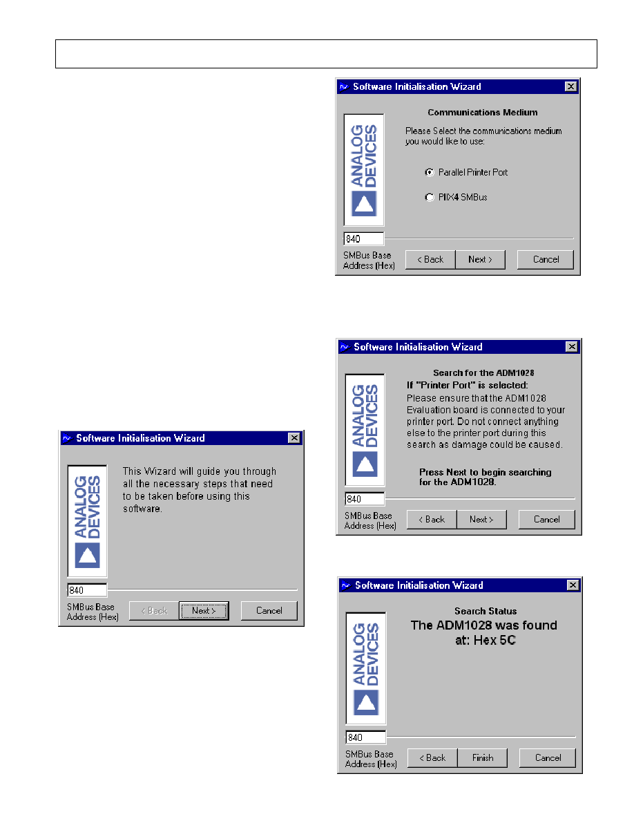
When the program is selected the Software Initialisation
Wizard will appear first.
Click on "Next" to go to the next screen, which will
allow the user to choose between connecting the
evaluation board via the printer port or via the SMBus.
Once the Communications medium has been selected,
click on "Next" to go to the next screen. When you are
ready for the evaluation software to begin searching for the
device on the chosen medium, click on "Next".
The software will search for the ADM1028 and if it finds
it the following screen will appear.