EVAL-ADM1030/31
a
REV. PrA 10/2000
Information furnished by Analog Devices is believed to be accurate and
reliable. However, no responsibility is assumed by Analog Devices for its
use, nor for any infringements of patents or other rights of third parties
which may result from its use. No license is granted by implication or
otherwise under any patent or patent rights of Analog Devices.
One Technology Way, P.O. Box 9106, Norwood, MA 02062-9106, U.S.A.
Tel: 781/329-4700
World Wide Web Site: http://www.analog.com
Fax: 781/326-8703
Analog Devices, Inc., 2000
Evaluation Board for ACPI Temperature
Monitor and PWM Fan Controller
Preliminary Technical Data
PRELIMINAR
Y
TECHNICAL
DA
TA
FEATURES
Optimized for Pentium III
®
®
®
®
®
:- Allows Reduced
Guardbanding
Programmable (ACPI) and Automatic Fan Speed Control
Automatic Fan Speed Control allows control Independant
of CPU Intervention after initial setup.
Control Loop minimizes Acoustic Noise and Battery
Consumption
RPM Feedback mode to maintain constant fan speed
Remote Temperature measurement accurate to 1°C using
Remote Diode (2 channels for ADM1031, 1 for ADM1030)
0.125°C Resolution on External Temperature Channels
Local Temperature Sensor with 0.25°C resolution
Pulse Width Modulation Fan Control (PWM) (two fans for
ADM1031, one fan for ADM1030)
Programmable PWM Frequency
Programmable PWM Duty Cycle
Tach Fan Speed Measurement (One Channel for
ADM1030, Two for ADM1031 )
Analog Inputs to measure Fan Speed of 2-wire fans (using
Sense Resistor)
2-Wire Serial System Management Bus(SMBus) with ARA
Over-Temperature
THERM
THERM
THERM
THERM
THERM Output Pin
Programmable
INT
INT
INT
INT
INT Output Pin
Configurable Offsets for Temperature Channels
3V to 5.5V Supply Range
Shutdown Mode to Minimize Power Consumption
Limit Comparisons of all Monitored Values
APPLICATIONS
Notebook PC's, Network Computers and Personal
Computers
Microprocessor Based Office Equipment.
I N T R O D U C T I O N
The ADM1030/31 evaluation board allows the
ADM1030/31 PC Temperature Monitor and PWM Fan
Controller to be quickly and easily evaluated using a
personal computer. Using the evaluation board and the
accompanying software the ADM1030/31 can be
interfaced to any personal computer running Windows
TM
95 or Windows
TM
98 via the computer's parallel port.
The evaluation board allows the input and output
functions of the ADM1030/31 to be exercised without the
need for external components. The software allows control
and monitoring of the ADM1030/31's internal registers.
THE ADM1030/31
The following is a brief description of the ADM1030/31
and a system overview. Further information can be found
on the ADM1030 and ADM1031 datasheet.
The ADM1030 and ADM1031 function in a very similar
manner. The main difference is that the ADM1031 is dual
channel and the ADM1030 is single channel i.e. the
ADM1031 has a second remote temperature measurement
channel, a second fan speed measurement channel and a
second PWM fan speed control channel.
The ADM1030/31 is an ACPI compliant two/three
channel digital thermometer and under/over temperature
alarm, for use in personal computers. A PWM Fan
Control Output controls the speed of cooling fans. The
speed of these fans may be monitored using the Tach
Inputs. A dedicated Fan Speed Control Loop provides
control even without CPU Intervention.
The device has a programmable
INT output to indicate
error conditions. The
THERM pin is a failsafe output for
over temperatire conditions.
EVALUATION SYSTEM PACKAGE CONTENTS
The evaluation system contains the following items
1. The ADM1030/31 Evaluation Board
2. Centronics Cable
3. CD containing this application note, datasheet and the
ADM1030/31 evaluation software.
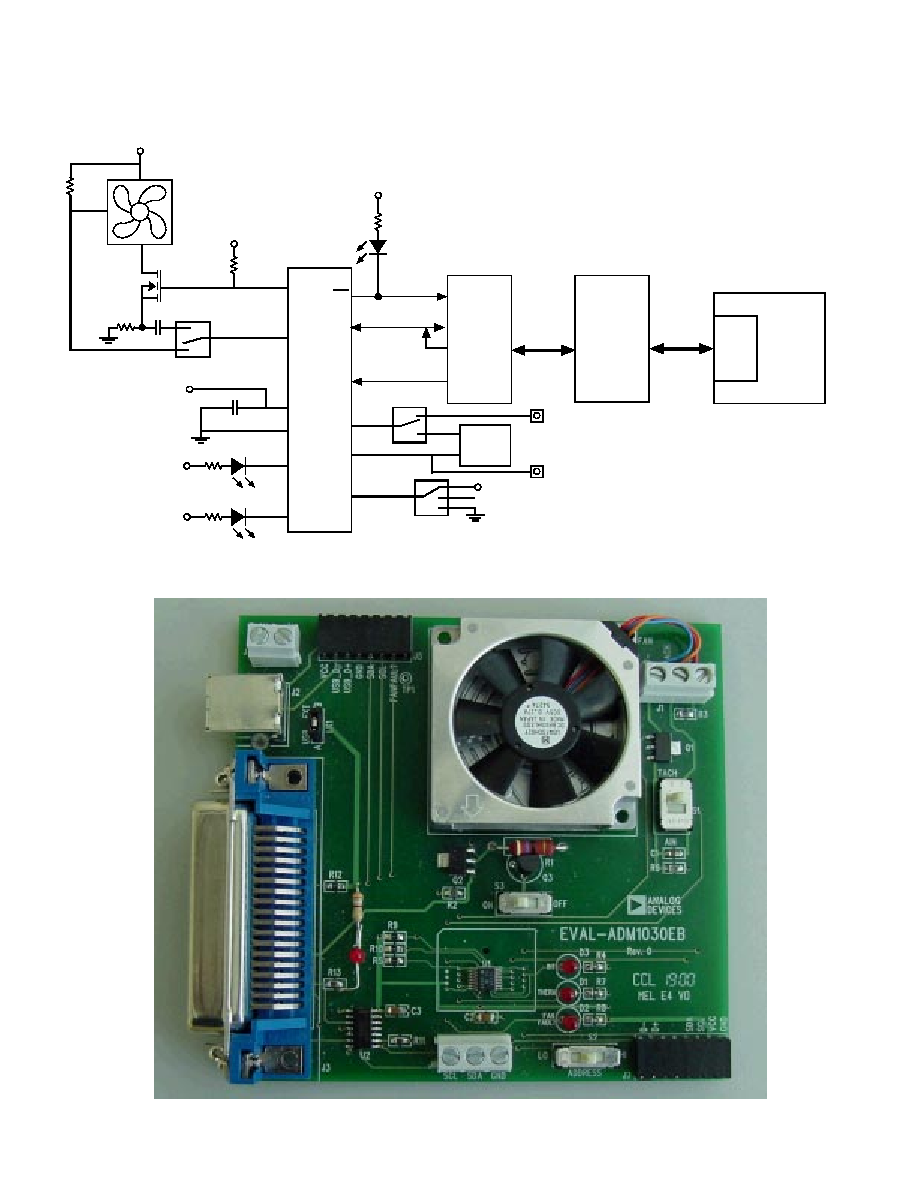
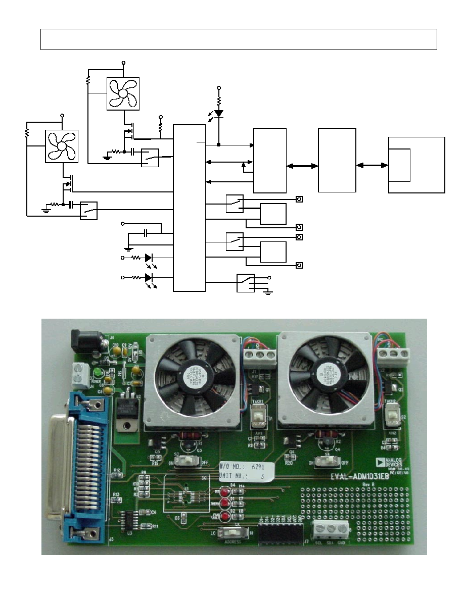
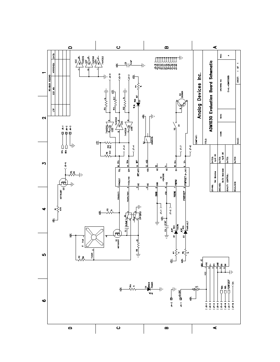
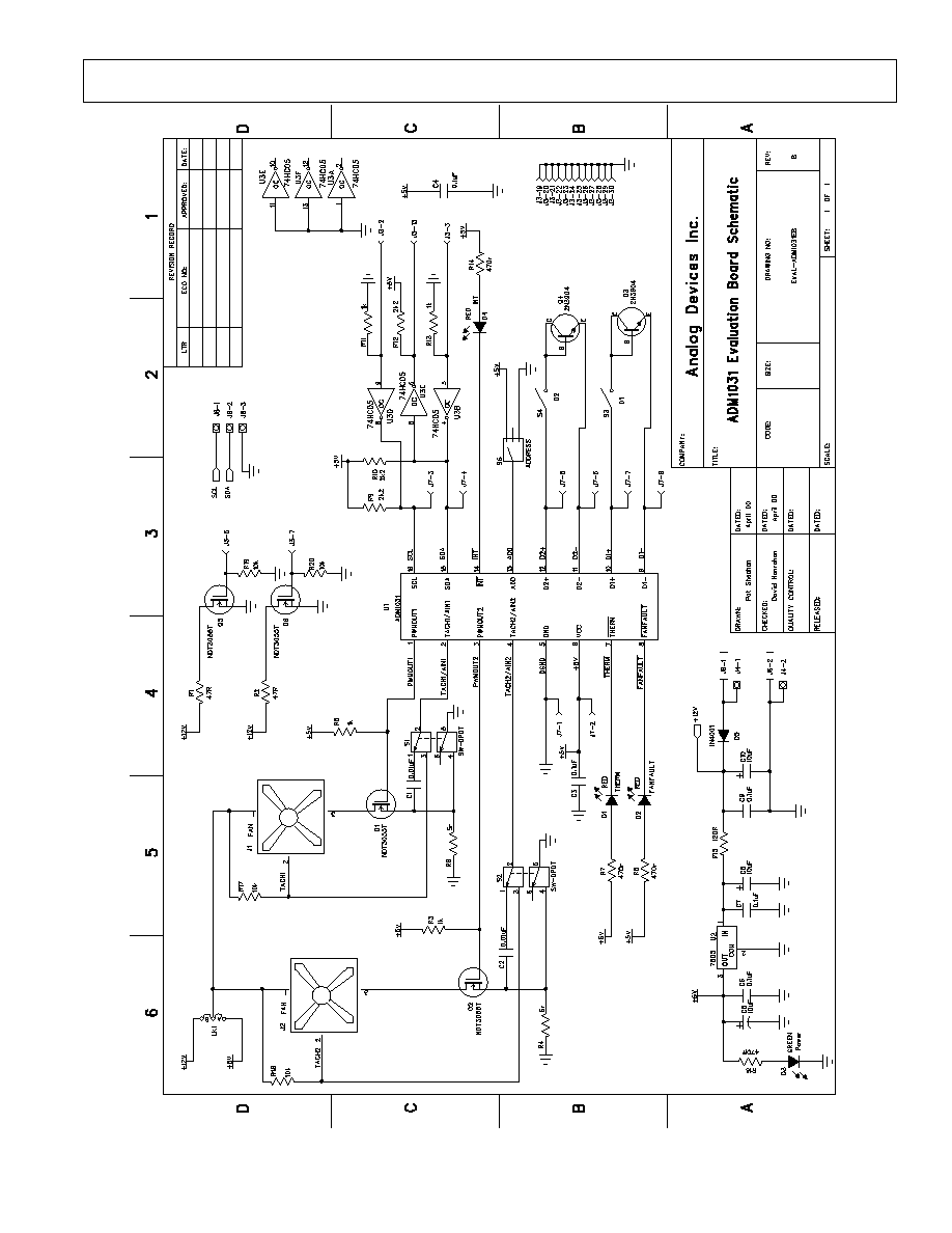
EVALUATION BOARD HARDWARE
The ADM1030/31 evaluation board contains the
following main components which can be identified from
the block diagram, printed circuit board silk screen and
schematic diagram of Figures1, 2 and 3 overleaf.
1. ADM1030 or ADM1031 IC
2. 1 or 2 NPN sensor transistors (depending on whether
ADM1030 or ADM1031 IC is used)
3. LED indicators
4. Interface Buffers
5. Connector for parallel interface.
6. Test Connector for connecting to remote thermal
sensor (J7)
7. Fan (1 or 2 depending on IC).