
Advanced Monolithic Systems, Inc. 6680B Sierra Lane, Dublin, CA 94568 Phone (925) 556-9090 Fax (925) 556-9140
Advanced
AMS1004-2.5
Monolithic
MICROPOWER VOLTAGE REFERENCE
Systems
FEATURES
APPLICATIONS
∑
∑
Ī
20 mV (
Ī
0.3%) max. initial tolerance (A grade)
∑
∑
Battery Powered Systems
∑
∑
Operating Current 20
Ķ
Ķ
A to 20mA
∑
∑
Instrumentation
∑
∑
Low Voltage Reference 2.5V
∑
∑
A/D, D/A Converters
∑
∑
Max. 0.6
Dynamic Impedance (A grade)
∑
∑
Temperature measurement
∑
∑
Low Temperature Coefficient
∑
∑
Current sources
∑
∑
1.2V Device also available, AMS1004-1.2
∑
∑
Notebook/Personal Computer
∑
∑
Monitors/ VCR/ TV
∑
∑
Pagers
GENERAL DESCRIPTION
The AMS1004-2.5 is a two-terminal micropower band-gap voltage reference diode. It features a very low dynamic impedance
and good temperature coefficient, operating over a 20
Ķ
A to 20mA current range. On-chip trimming is used to provide tight
voltage tolerance. Since the AMS1004-2.5 is a band-gap reference, uses only transistors and resistors, low noise and good
long term stability result. Careful design of the AMS1004-2.5 has made the device exceptionally tolerant of capacitive
loading, making it easy to use in almost any reference application. The wide dynamic operating range allows its use with
widely varying supplies with excellent regulation. The extremely low power drain of the AMS1004-2.5 makes these reference
diodes useful for micropower circuitry. This voltage reference can be used to make portable meters, regulators or general
purpose analog circuitry with battery life approaching shelf life.
Further more, the wide operating current allows it to replace older references with a tight tolerance part, making it attractive
for use in systems where accuracy was previously obtained at the expense of power consumption and trimming.
The AMS1004-2.5 is operational over a temperature range of 0
į
C to 70
į
C and is available in TO-92, SO-8 and SOT-89
packages. For extended temperature range contact factory.
ORDERING INFORMATION:
TOL.
PACKAGE TYPE
OPERATING
TO-92
8 LEAD SOIC
SOT-89
TEMPERATURE RANGE
Ī
20mV AMS1004-2.5AN
AMS1004-2.5AS
AMS1004-2.5AL
0 to 70
į
C
Ī
40mV AMS1004-2.5BN
AMS1004-2.5BS
AMS1004-2.5BL
0 to 70
į
C
Advanced Monolithic Systems, Inc. 6680B Sierra Lane, Dublin, CA 94568 Phone (925) 556-9090 Fax (925) 556-9140
AMS1004-2.5
ABSOLUTE MAXIMUM RATINGS
Reverse Current
30mA
Storage temperature
-55
į
C to +150
į
C
Forward Current
10mA
Soldering information
Operating Temperature Range
0
į
C to 70
į
C
TO-92 package: 10 sec.
260
į
C
SOIC package: Vapor phase (60 sec)
215
į
C
Infrared (15 sec.)
220
į
C
SOT-89 package: 10 sec.
265
į
C
ELECTRICAL CHARACTERISTICS
Electrical Characteristics at I
R
= 100
Ķ
A, and T
A
= +25įC unless otherwise specified.
Parameter
Conditions
AMS1004A-2.5
Min Typ Max
AMS1004B-2.5
Min Typ Max
Units
Reverse Breakdown
Voltage (Note 4)
I
R
- 100
Ķ
A
2.480
2.500
2.520
2.460
2.500
2.540
V
Reverse Dynamic
Impedance (Note 4)
I
R
- 100
Ķ
A, f = 20Hz
0.2
0.60
0.2
0.60
Reverse Breakdown
Voltage Change with
current (Note 4)
10
Ķ
A
I
R
1mA
1mA
I
R
20mA
1.0
10
1.0
10
mV
Min. Operating
Current (Note 4)
12
10
20
12
10
20
Ķ
A
Ķ
A
Wide Band Noise
(Note 5)
I
R
- 100
Ķ
A,
10Hz
f
10kHz
120
120
Ķ
V
Temperature Coeff.
(Note 6)
25
50
ppm/įC
Long Term Stability
(Note 5)
T
A
=25įCĪ.1įC
T = 1000 Hr
20
20
ppm
Note 1:
Absolute Maximum Ratings indicate limits beyond which damage to the device may occur. Operating Ratings indicate conditions for which the device is
intended to be functional, but do not guarantee specific performance limits. For guaranteed specifications and test conditions, see the Electrical Characteristics
.
The
guaranteed specifications apply only for the test conditions listed.
Note 2:
For elevated temperature operation, T
j
max is +100įC
Thermal Resistance
TO-92
SO-8
SOT-89
JA
(junction to ambient)
170įC/W (0.125" leads)
165įC/W
160įC/W
Note 3:
Parameters identified with boldface type apply at temperature extremes. All other numbers apply at T
A
= T
J
= 25įC.
Note 4:
Guaranteed and 100% production tested.
Note 5:
Guaranteed but not 100% production tested. These limits are not used to calculate average outgoing quality levels.
Note 6:
The average temperature coefficient is defined as the maximum deviation of reference voltage at all measured temperatures between the operating T
MAX and
T
MIN
, divided by T
MAX
- T
MIN
. The measured temperatures are 0
į
C, 25
į
C, 70
į
C.
Advanced Monolithic Systems, Inc. 6680B Sierra Lane, Dublin, CA 94568 Phone (925) 556-9090 Fax (925) 556-9140
AMS1004-2.5
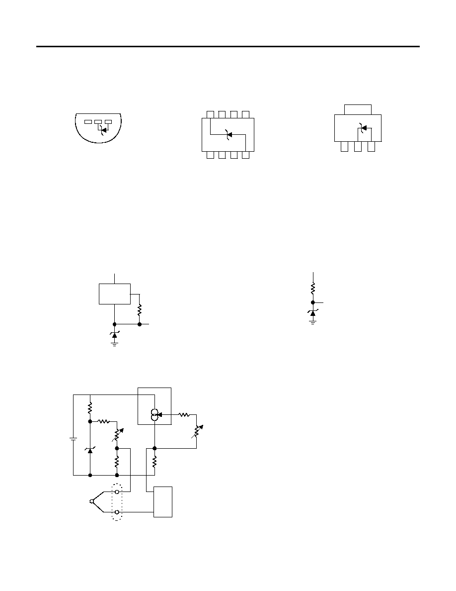
PIN CONNECTIONS
TO-92
SO-8
SOT-89
Plastic Package (N)
SO Package (S)
(L)
1
2
3
1
2
8
4
3
7
5
6
N/C
N/C
N/C
N/C N/C
N/C
+
-
N/C
-
+
1
2
3
Bottom View
Top View
Top View
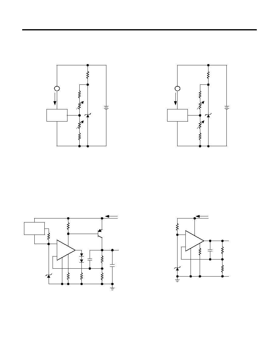
TYPICAL APPLICATIONS
Wide Input
Micropower Reference
Range Reference
from 9V Battery
3.3k
LM334
OUT
2.5V
AMS1004-2.5
V
IN
= 3.7V TO 30V
AMS1004-2.5
2.5V
200k
9V
Micropower Thermocouple Cold Junction Compensator
+
LM334
AMS1004-2.5
R1
R2
ZERO ADJ
100k
1M
1%
18k
2k
1%
TC ADJ
500
METER
3V
LITHIUM
+
-
V
+
V
-
R
THERMOCOUPLE
+
-
COLD JUNCTION
ISO THERMAL
WITH LM334
Adjustment Procedure
1. Adjust TC ADJ pot until voltage across R1 equals Kelvin temperature
multiplied by the thermocouple Seebeck coefficient.
2. Adjust ZERO ADJ pot until voltage across R2 equals the thermocouple
Seebeck coefficient multiplied by 273.2.
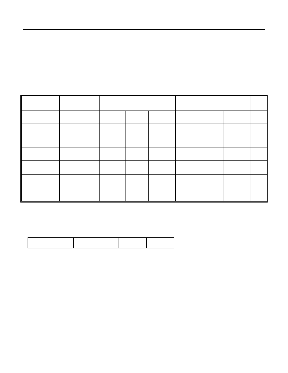
Thermocouple Seebeck R1 R2 Voltage Voltage
Type Coefficient (
) (
) Across R1 Across R2
(mV/
į
į
C) @ 25
į
į
C (mV) (mV)
J 52.3 523 1.24k 15.60 14.32
T 42.8 432 1k 12.77 11.78
K 40.8 412 953
12.17 11.17
S 6.4 63.4 150
1.908 1.766
Typical supply current 50
Ķ
A
Advanced Monolithic Systems, Inc. 6680B Sierra Lane, Dublin, CA 94568 Phone (925) 556-9090 Fax (925) 556-9140
AMS1004-2.5
TYPICAL APPLICATIONS
(Continued)
0
į
į
C - 100
į
į
C Thermometer
0
į
į
C - 100
į
į
C Thermometer
AMS1004-2.5
1k
R1
8k
R2
1k
R3
100
R4
220
3V
R
V
-
V
+
LM334
M
0-100
Ķ
A
I
OUT
Calibration
1. Short AMS1004-2.5, adjust R3 for I
OUT
= temp at 1
Ķ
A/
į
K
2. Remove short, adjust R2 for correct reading in
į
C
AMS1004-2.5
150
R1
4k
R2
1k
R3
50
R4
100
3V
R
V
-
V
+
LM334
M
0-50
Ķ
A
I
OUT
Calibration
1. Short AMS1004-2.5, adjust R3 for I
OUT
= temp at 1.8
Ķ
A/
į
K
2. Remove short, adjust R2 for correct reading in
į
F
Micropower* 5V Regulator
Micropower* 10V Reference
150pF
AMS1004-2.5
100k
10M
2.2k
7
4
6
2
3
-
+
V
IN
5.2V
I
Q
V
O
= 5V
I
L
100mA
LM4250C
8
R
V
-
V
+
LM334
2k
100k
47k
2N2905
1N457
1N457
+
4.7
Ķ
F
TANTALUM
*I
Q
40
Ķ
A
150pF
AMS1004-2.5
1.5M
500k
22M
500k
7
4
6
3
2
-
+
V
IN
= 15V
I
Q
10V
LM4250C
8
*I
Q
20
Ķ
A standby current
Advanced Monolithic Systems, Inc. 6680B Sierra Lane, Dublin, CA 94568 Phone (925) 556-9090 Fax (925) 556-9140
AMS1004-2.5
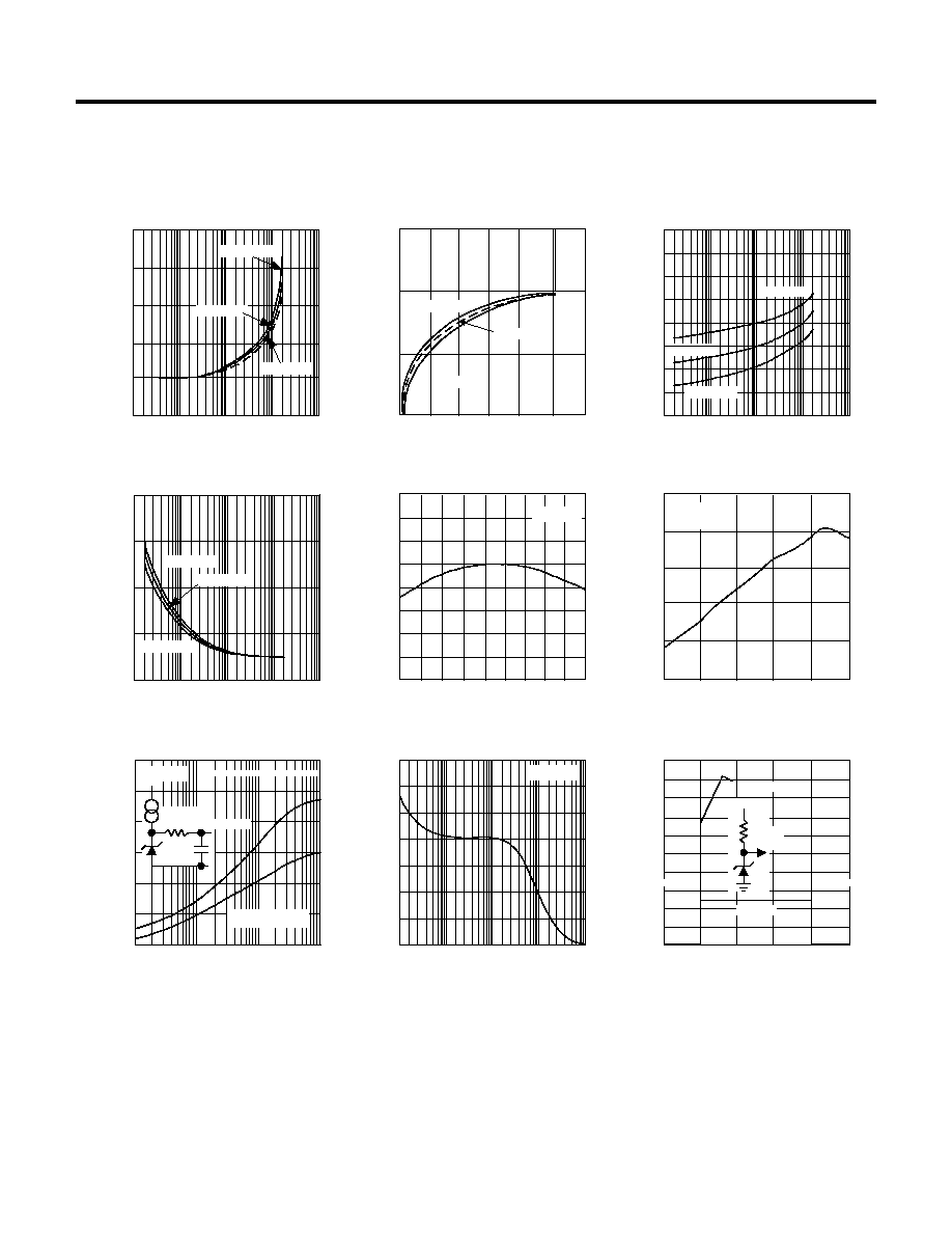
TYPICAL PERFORMANCE CHARACTERISTICS
-4
4
8
16
0.1
1
10
100
Reverse Characteristics
0
OUTPUT VOLTAGE CHANGE (mV)
T
A
=25į C
0.1
1000
0.1
1
10
100
Reverse Dynamic Impedance
1
100
DYNAMIC IMPEDANCE (
)
0.01
0
0.4
1.6
0.1
1
10
100
0.8
0.01
REVERSE CURRENT (mA)
REVERSE CURRENT (mA)
0
0.5
1.0
1.5
2.0
2.5
0.1
100
10
3.0
REVERSE VOLTAGE (V)
REVERSE CURRENT (
Ķ
A)
1
Reverse Characteristics
Forward Characteristics
FORWARD CURRENT (mA)
FORWARD VOLTAGE (V)
10
100
1k
10k
100k
0.1
1k
10
Reverse Dynamic Impedance
1M
FREQUENCY (Hz)
DYNAMIC IMPEDANCE (
)
1
10k
100
-55
5
25 45 65 85 105
2.530
2.490
125
REFERENCE VOLTAGE (V)
Temperature Drift
0
10
0
1.0
3.0
0
200
400
600
TIME (
Ķ
s)
Response Time
VOLTAGE SWING (V)
2.0
~
~
~
~
0
400
800
1200
1400
100
1k
10k
100k
Noise Voltage
200
1000
NOISE (nV/
Hz)
I
R
= 100
Ķ
A
10
FREQUENCY (Hz)
600
100
1k
10k
100k
CUTOFF FREQUENCY (Hz)
INTEGRATED NOISE (
Ķ
V
)
0
20
40
60
80
100
120
TEMPERATURE (į C)
2.510
2.470
2.460
-35 -15
I
R
= 100
Ķ
A
T
A
=-55į C
T
A
=125į C
T
A
=125į C
T
A
=-55į C
T
A
=25į C
T
A
=-55į C
T
A
=25į C
T
A
=125į C
T
A
=25į C
I
R
= 100
Ķ
A
T
A
=-55į C
T
A
=25į C
T
A
=125į C
I
R
= 100
Ķ
A
100
Ķ
A
OUTPUT
OUTPUT
100k
INPUT
OUTPUT
INPUT
SINGLE POLE LOW PASS
SHARP CUTOFF
FILTER
Filtered Output Noise
0.01
10
12
1.2
2.520
2.500
2.480
2.450