 | –≠–ª–µ–∫—Ç—Ä–æ–Ω–Ω—ã–π –∫–æ–º–ø–æ–Ω–µ–Ω—Ç: AMS26A | –°–∫–∞—á–∞—Ç—å:  PDF PDF  ZIP ZIP |

Advanced Monolithic Systems, Inc. www.advanced-monolithic.com Phone (925) 443-0722 Fax (925) 443-0723
Advanced
AMS26
Monolithic
VOLTAGE DETECTOR
Systems
FEATURES
APPLICATIONS
∑
∑
Very Low Supply Current
∑
∑
CPU and Logic Circuit Reset
∑
∑
Wide Operating Voltage Range
∑
∑
Portable and Battery Powered Equipment
∑
∑
2% Precision Voltage Detection
∑
∑
Memory Battery Back-Up Circuit
∑
∑
Detection Threshold from 2V to 6V in 0.1V increments
∑
∑
Window Comparator
∑
∑
5mA Sink Current Capability
∑
∑
Cellular Phones
∑
∑
5% Typical Hysteresis
∑
∑
Pagers
GENERAL DESCRIPTION
The AMS26 series are voltage detector ICs featuring a high accuracy detector threshold of
±
2.0% and ultra-low supply
current. Internal circuit contains a precision voltage reference, a comparator, resistor network, and an output driver. The
AMS26 has an N-channel open drain output.
The detector threshold is set from 2.0V to 6.0V in 0.1V increments, thus making it easy to use in a variety of supervisory
applications including microprocessor reset circuits, memory battery back-up circuit, battery checker, power failure detector
and portable and battery powered electronics.
AMS26 is available in TO-92 and the sub-miniature 3-pin SOT-23 surface mount package.
ORDERING INFORMATION
OUTPUT
PACKAGE TYPE
OPERATING
TYPE
TO-92
3 LEAD SOT-23
TEMPERATURE RANGE
OPEN DRAIN
AMS26N-XA
AMS26M-XA
-30 to +80
∞
C
X= Detector Threshold Setting.
PIN CONNECTIONS
TO-92
3L SOT-23
Plastic Package (N)
(M)
1
2
3
V
OUT
V
DD
GND
V
OUT
GND
V
DD
Bottom View
Top View
Advanced Monolithic Systems, Inc. www.advanced-monolithic.com Phone (925) 443-0722 Fax (925) 443-0723
AMS26
ABSOLUTE MAXIMUM RATINGS
(Note 1)
Supply Voltage
16V
Power Dissipation : TO-92 package
300mW
Output Voltage
V
SS
- 0.3V toV
DD
+0.3V
SOT-23 package
150mW
Output Current
70mA
Storage Temperature
-40
∞
C to +125
∞
C
Operating Temperature Range
-30
∞
C to +80
∞
C
Lead Temperature (Soldering 10 sec)
230
∞
C
ELECTRICAL CHARACTERISTICS
Electrical Characteristics at T
A
=25∞C, unless otherwise noted.
PARAMETER
CONDITIONS
(Note 2)
Min.
AMS26-X
Typ.
Max.
Units
Detector Threshold (V
DET
)
-2.0
+2.0
%
Detector Threshold Hysteresis
(V
DET
) * 3%
(V
DET
) * 7%
V
Supply Current
V
IN
= 2.0V
1.0
3.0
µ
A
V
IN
= 3.0V
1.3
3.4
V
IN
= 4.0V
1.6
3.8
V
IN
= 5.0V
2.0
4.2
Operating Voltage
1.50
10.00
V
Output Current
V
IN
= 2.0V
1.5
7.7
mA
V
IN
= 3.0V
3.0
10.1
V
IN
= 4.0V
4.0
11.5
V
IN
= 5.0V
5.0
13.0
Output Delay Time
100
µ
s
Detector Threshold Temperature
Coefficient
-30
∞
C
T
A
+80
∞
C
±
100
ppm/
∞
C
Note 1: Absolute Maximum Ratings are limits beyond which damage to the device may occur. For guaranteed performance limits and associated test conditions, see
the Electrical Characteristics tables.
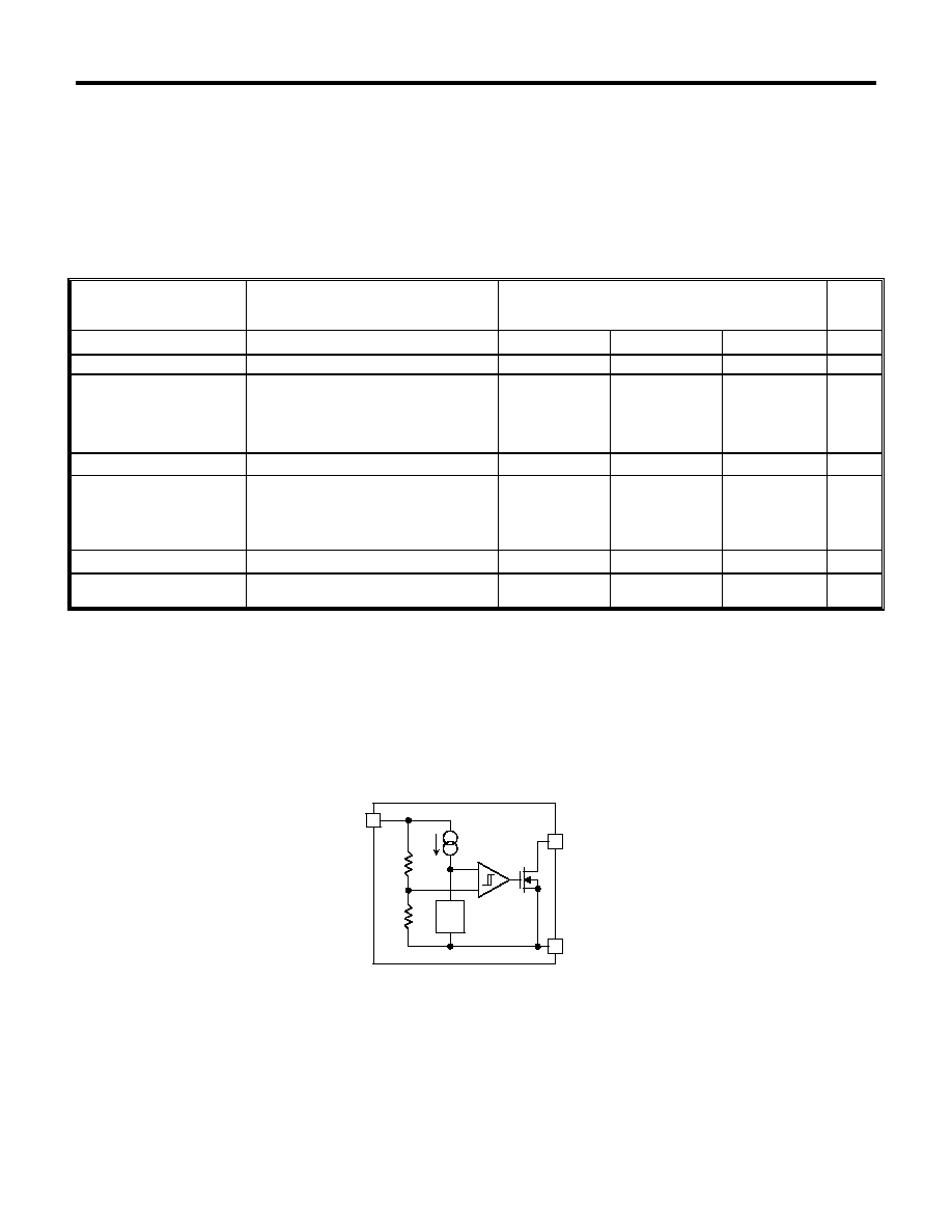
BLOCK DIAGRAM
V
REF
3
+
-
V
DD
OUT
GND
1
2

Advanced Monolithic Systems, Inc. www.advanced-monolithic.com Phone (925) 443-0722 Fax (925) 443-0723
AMS26
TIME CHART
OUTPUT DELAY TIME
TEST CIRCUITS
Detector Threshold Test Circuit
Output Current Test Circuit
Detector Threshold Hysteresis
Released Voltage
Detected Voltage
Minimum Operating Voltage
GND
GND
Supply Voltage
(V
DD
)
Output Voltage
(OUT)
t
PLH
A
B
AMS26A
SERIES
V
DET
V
DD
GND
OUT
R
V
SS
V
DD
V
SS
100k
AMS26A
SERIES
+V
DS
V
DD
GND
OUT
I
OUT
V
SS
V
DD
V
SS
Supply Voltage
(V
DD
)
Output Voltage
(OUT)
GND
GND
3.5V
7.0V
1.2V
+V
DET
+2.0V
t
PHL
t
PHL
A
B
Output Delay Time t
PHL
is defined as the time period from Time A
through Time B, when the time at which a pulse voltage that increases
from 1.2V to +V
DET
+2.0V is applied to V
DD
is Time A, and the time at
which the output reaches 3.5V under the conditions that the output pin
(OUT) is pulled up to 7V by a resistor of 100k
is Time B.

Advanced Monolithic Systems, Inc. www.advanced-monolithic.com Phone (925) 443-0722 Fax (925) 443-0723
AMS26
TYPICAL APPLICATIONS
CPU Reset Circuit
Input Voltage to AMS26 is the same as the input voltage to CPU.
Input Voltage to AMS26 is different from the input voltage to CPU.
Output Delay Time Circuit
Voltage Level Indicator Circuit (lighted when the power runs out)
Detector Threshold Changing Circuit
Window Comparator Circuit
AMS26A
SERIES
RESET
GND
CPU
V
DD
V
DD
V
DD
GND
OUT
R
100
AMS26A
SERIES
RESET
GND
CPU
V
DD
V
DD2
V
DD
GND
OUT
R
100
V
DD1
AMS26A
SERIES
RESET
GND
CPU
V
DD
V
DD
V
DD
GND
OUT
R
100
AMS26A
SERIES
GND
OUT
V
DD
V
DD
AMS26A
SERIES
V
DD
V
DD
GND
OUT
R1
R2
C
Changed Detector Threshold
)
(-V
R2
R2
R1
DET
+
=
Hysteresis Voltage
)
(-V
R2
R2
R1
HYS
+
=
When the value of R1 becomes excessively large, the detector threshold
detected may differ from the value calculated using above formula.
AMS26A
SERIES
V
DD
GND
OUT
AMS26A
SERIES
V
DD
GND
OUT
100
V
DET1
V
DET2
OUT
V
DD
V
DD
V
SS
OUT
V
SS
V
DET
1
V
DET
2