 | –≠–ª–µ–∫—Ç—Ä–æ–Ω–Ω—ã–π –∫–æ–º–ø–æ–Ω–µ–Ω—Ç: ACT8611 | –°–∫–∞—á–∞—Ç—å:  PDF PDF  ZIP ZIP |
eroflex Circuit Technology - Advanced Multichip Modules © SCD861X REV 2 5/16/00
STATUS
SYNC_OUT
OUT_COM
INHIBIT
SYNC_IN
IN_COM
VIN+
VIN-
VO+
VO-
OUTPUT
CONTROL
CIRCUITRY
INPUT
CONTROL
CIRCUITRY
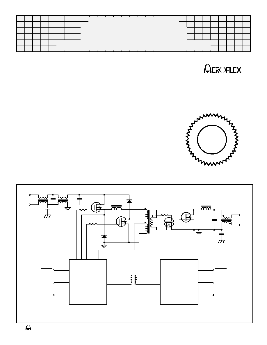
Figure 1 ≠ Block
Diagram
Features
s
Radiation Environment
q
Total Dose 100K Rad (Si)
q
No SEE or SEU to 20 MeV/cm
2
/mg
s
-55
o
C to 85
o
C Baseplate Mounting Temperature
s
50W Power Output, +5V, +12V, +15V, -12V and ≠15V Output Versions Available
s
50V Input Bus
s
Internal EMI Suppression Circuitry designed to meet the requirements of MIL-STD-461C
s
Short Circuit Protected
s
Input Undervoltage Shutdown
s
Output Overvoltage Shutdown
s
Overtemperature Shutdown
s
Input Shutdown Control
s
Input Synchronization Control
s
Output Synchronization Control
s
Output Status Signal
s
Packaging ≠ Non-Hermetic COB in a 3" x 4" x .9" housing with D connector
CIRCUIT TECHNOLOGY
www.aeroflex.com
Radiation Hardened
50 Watt Power Supply Module
ACT 861X Series
F
I
E
I
D
C
E
R T
A
E
R
O
F
L E
X L A
B
S
I
N
C
.
ISO
9001
Advanced

A
A
Aeroflex Circuit Technology
SCD861X REV 2 5/16/00 Plainview NY (516) 694-6700
2
General Description
Aeroflex's ACT861X series of power supply modules are radiation hardened 50 Watt units
designed for use in space applications. Using a double ended forward topology with synchronous
rectifiers achieves high efficiency, and the use of Chip-On-Board (COB) construction together with
planar magnetics allows Aeroflex to provide space quality components at down-to-earth prices.
The ACT861X series are full featured single output converters, with EMI filtering, short circuit
protection, input undervoltage shutdown, output overvoltage shutdown, overtemperature shutdown,
input shutdown control and synchronization on both input and output sides. Other output voltages
are available upon request.
Aeroflex's ACT861X series of power supply modules are radiation hardened 50 Watt units
designed for use in space applications. The block diagram shown in Figure 1 uses a two transistor
(double ended) forward topology to minimize voltage stresses on the semiconductors, and
synchronous rectifiers are used to achieve high efficiency. These full featured converters are
intended to be used in the space environment, conduction cooled to a baseplate and
interconnected to the system via a D connector. The converter includes features such as input
undervoltage shutdown, output overvoltage shutdown, overtemperature shutdown, input shutdown
control and synchronization on both input and output sides. No optocouplers are used in the
converter to assure long term total dose hardness.
The ACT861X series is fabricated as an encapsulated Chip-On-Board module in an aluminum
housing. The Outline Drawing is shown in Figure 2.
The input undervoltage shutdown disables the converter when the input bus is below the
minimum specified setpoint. Nominal input current will be the shutdown current specified. This
prevents the converter from generating low output voltages in the event of bus undervoltages and
drawing high input currents when attempting to power the rated load with these low bus input
voltages. When the input bus voltage is above the minimum specified in Table 1 the converter
commences operation.
Overtemperature protection is integral to the ACT861X series. An internal temperature sensor
mounted near the higher power dissipating components shuts the converter off if the mounting
temperature is above the threshold specified in Table 1. When the converter cools off it will turn
back on with no cycling of input power required.
The output overvoltage circuit uses a portion of the output voltage derived to power the internal
logic (the bootstrap supply) to measure indirectly the output voltage. This voltage is sensed, and if it
exceeds a predetermined threshold the converter will cycle at a nominal 100Hz frequency
attempting to restart.
Control of the ACT861X is achieved via the INHIBIT pin. This pin may be used as both an internal
temperature monitor and to control the module. When INHIBIT is shorted to the IN_COM pin the
module is disabled. Nominal current flowing through the INHIBIT line at this time is less than 1mA,
and the on/off threshold is 6V above the negative return. When the converter temperature sensor is
at ≠55∞C the INHIBIT line will be approximately 8.7V; at 85∞C it will be approximately 6.7V. This
affords the user a convenient way to measure the converter internal temperature.
Synchronization may either be referenced to the output ground of the converter or input ground.
When synchronization is referenced to the input ground a low impedance clock waveform,
approximately 50% duty cycle, TTL compatible between 450 and 500KHz, should be applied to the
SYNC_IN terminal and the IN_COM terminal. This will synchronize the switching power converter
although not the feedback oscillator. If it is desired to synchronize both the power converter and
feedback oscillator a low impedance clock waveform, approximately 50% duty cycle, TTL
compatible between 450 and 500KHz, should be applied to the SYNC_OUT terminal and the
OUT_COM terminal.
The STATUS output is an open collector signal, active low, referenced to OUT_COM that is
asserted when the output voltage is within ±10% of the nominal output voltage.

A
A
Aeroflex Circuit Technology
SCD861X REV 2 5/16/00 Plainview NY (516) 694-6700
3
Table 1 ≠ Performance Specifications
(T
C
= -55
∞
C to +85
∞
C, V
IN
= +50V DC ±5%, C
L
= 0, Unless otherwise specified)
Parameter
ACT8601
ACT8602
ACT8603
ACT8604
ACT8605
Units
Nominal Output Voltage
+5
+12
+15
-12
-15
Volts
Regulation, No Load to Full Load
0.1
0.05
0.05
0.05
0.05
Volts, Maximum
Stability, Over Operating Temperature
0.1
0.05
0.05
0.05
0.05
Volts, Maximum
Regulation, Over Line Voltage
0.05
0.025
0.025
0.025
0.025
Volts, Maximum
Ripple
50
25
25
25
25
mVolts RMS,
Maximum
Output Overvoltage Shutdown
+5.5
+13.2
+16.5
-13.2
-16.5
Volts, Maximum
Efficency, at Full Load
85
88
88
88
88
%, Minimum
Output Current
10
4.2
3.3
4.2
3.3
Amperes, Maximum
Output Current Limit
12
5
4
5
4
Amperes, Maximum
Output Voltage Accuracy
±2 %
Output Power
50
W, Maximum
Input Voltage
40
Volts, Minimum
Input Voltage
60
Volts, Maximum
Input Voltage, Transient
100
Volts, Maximum
for 1 second
Input EMI
Complies with MIL-STD-461C
≠
Input Undervoltage Threshold
38.5
Volts, Maximum
Input Current, at Full Load
1.5
Amperes, Maximum
Input Current, at No Load
0.15
Amperes, Maximum
Input Current, Shutdown Asserted
20
mAmperes, Maximum
Input Output Isolation
10M
at 250V Minimum
≠
Switching Frequency
200
KHz, Nominal
Transient Response
50% load change, 5% Maximum deviation, returns to regulation band
in 1msec.
≠
Overshoot
At Turn On, Turn Off and Power Failure: None
≠
Output Short Circuit Duration
Will Withstand continious short without damage
≠
Radiation, Total Dose
100
KRad (Si),
Maximum
Radiation, SEE/SEB
20
MeV/cm
2
/mg,
Maximum
Thermal Shutdown, Case
85∞C
Minimum
Operating Temperature, Case
-55∞C to +85∞C
≠
Storage Temperature
-65∞C to +125∞C
≠

A
A
Aeroflex Circuit Technology
SCD861X REV 2 5/16/00 Plainview NY (516) 694-6700
4
3.500
3.000
3.500
.50
3.438
4.000
.281
TYP
.61
(1.852)
.91
.900
See
Note 1
.500 TYP
Notes:
1. Input / Output Connector ITT Cannon DBMMMD13H3PJ, mating
with DBMM13W3S. Connector pin assignments are listed in Table 1.
2. Dimension Tolerances: 2 Place Decimals. ±.015
3 Place Decimals. ±.005
Figure 2 ≠ Package Outline Drawing
Table 2 ≠ Connector
Pin Assignments
Pin
Function
A1
CHASSIS COMMON
A2
VO+
A3
VO-
1
VIN-
2
SYNC_IN
3
NC
4
STATUS
5
OUT_COM
6
VIN+
7
INHIBIT
8
IN_COM
9
NC
10
SYNC_OUT
1
2
3
4
5
6
7
8
9
10
A1
A2
A3
4x
.171
.250
A
A
Aeroflex Circuit Technology
SCD861X REV 2 5/16/00 Plainview NY (516) 694-6700
5
Ordering Information
Model Number
Output Voltage
ACT 8611
+5V
ACT 8612
+12V
ACT 8613
+15V
ACT 8614
-12V
ACT 8615
-15V
C I R C U I T T E C H N O L O G Y
Aeroflex Circuit Technology
35 South Service Road
Plainview New York 11803
Telephone: (516) 694-6700
FAX: (516) 694-6715
Toll Free Inquiries: (800) 843-1553
Specifications subject to change without notice
www.aeroflex.com/act1.htm
E-Mail: sales-act@aeroflex.com