 | –≠–ª–µ–∫—Ç—Ä–æ–Ω–Ω—ã–π –∫–æ–º–ø–æ–Ω–µ–Ω—Ç: 127A | –°–∫–∞—á–∞—Ç—å:  PDF PDF  ZIP ZIP |

Data Sheet
September 1998
127A/B/C InGaAs Avalanche Photodetectors
The 127A/B/C APDs are compatible with industry-standard
packages.
Features
s
High performance at both 1.3 µm and 1.5 µm.
s
Suitable for use in harsh environments.
s
Higher sensitivity and longer wavelength response
than germanium APDs.
s
Permanently locked fiber alignment and high cou-
pling stability.
s
Reliable planar structure with InGaAsP layer and
dual guard ring for high-speed performance.
s
Wide bandwidth:
-- >1.0 GHz (127A)
-- >1.8 GHz (127B)
-- >2.5 GHz (127C)
s
Compatible with industry-standard packaging.
s
Applications for high data rates: up to 1.5 Gbits/s
(127A) or 2.5 Gbits/s (127B/C).
s
Low capacitance.
s
Standard pigtail is a multimode fiber with an
FC/PC connector; other pigtails or connectors
available on request.
Applications
s
Telecommunications
-- High-speed, long-haul communication systems
-- High-speed metropolitan area networks
-- Submarine cable communication systems
s
Military
-- Very low-noise receivers
-- Satellite transmission
-- Optical radar
-- Free-space optical communication systems
2
Lucent Technologies Inc.
Data Sheet
127A/B/C InGaAs Avalanche Photodetectors
September 1998
Description
The Lucent Technologies Microelectonics Group
127A/B/C InGaAs Avalanche Photodetectors (APDs)
are high-performance optical devices that are sensitive
at both 1.3 µm and 1.5 µm wavelengths. The APDs fea-
ture high sensitivity and wide bandwidths and are
capable of data rates up to 2.5 Gbits/s.
The APD chip is fabricated by vapor-phase epitaxy and
has a planar structure for high reliability. Common
applications include long-distance lightwave telecom-
munication systems and extremely sensitive optical
measurement systems.
The 127A/B/C APDs incorporate a hermetically sealed,
ceramic package that is bonded within a metal flange. A
multimode, fiber-optic pigtail, which is terminated with
an FC/PC connector, is aligned with the photodetector
chip by means of the metal flange. Other pigtails or con-
nectors are available upon request. The 127A and 127B
differ only in the bandwidth. The 127C has modified
crystalline layers to provide an increased bandwidth.
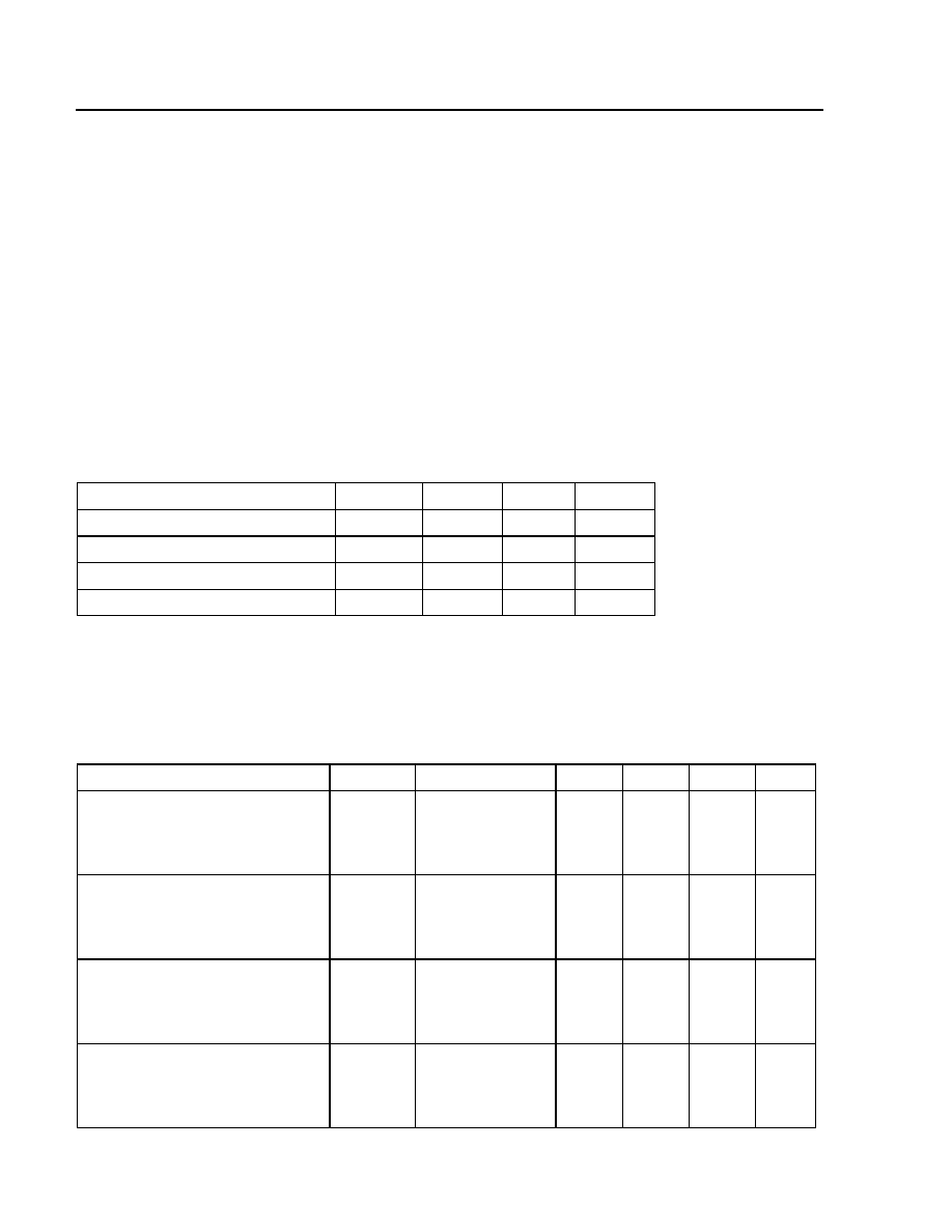
Absolute Maximum Ratings
Stresses in excess of the Absolute Maximum Ratings can cause permanent damage to the device. These are ab-
solute stress ratings only. Functional operation of the device is not implied at these or any other conditions in excess
of those given in the operational sections of the data sheet. Exposure to Absolute Maximum Ratings for extended
periods can adversely affect device reliability.
* Upper storage temperature is limited by multimode fiber.
Electrical Characteristics
Table 1. General Electrical Characteristics
All measurements at 25 ∞C, 1.3 µm light.
Parameter
Symbol
Min
Max
Unit
Operating Case Temperature
T
c
≠40
80
∞C
Storage Case Temperature*
T
stg
≠55
80
∞C
Reverse Current
I
r
--
1
mA
Lead Soldering Temperature/Time
--
--
275/10
∞C/s
Parameter
Symbol
Conditions
Min
Typ
Max
Unit
Breakdown Voltage:
127A
127B
127C
V
br
V
br
V
br
I
d
= 10 µA
I
d
= 10 µA
I
d
= 10 µA
55
55
45
65
65
60
95
95
90
V
V
V
V
br
Temperature Coefficient:
127A
127B
127C
--
--
--
0.15
0.15
0.12
0.20
0.20
0.15
0.30
0.30
0.20
%/∞C
%/∞C
%/∞C
Maximum Gain:
127A
127B
127C
M
max
M
max
M
max
--
--
--
30
30
30
--
--
--
--
--
--
--
--
--
Primary Dark Current:
127A
127B
127C
I
dp
I
dp
I
dp
--
--
--
--
--
--
5
5
10
10
10
15
nA
nA
nA

Lucent Technologies Inc.
3
Data Sheet
September 1998
127A/B/C InGaAs Avalanche Photodetectors
Electrical Characteristics
(continued)
Table 1. General Electrical Characteristics (continued)
All measurements at 25 ∞C, 1.3 µm light.
* The A coefficient and the breakdown voltage are given for each APD. The gain at any voltage (for M > 3) can be calculated from these para-
meters per: M = A/(V
br
≠ V).
Responsivity = quantum efficiency x coupling efficiency x gain x (
/1.24).
Parameter
Symbol
Conditions
Min
Typ
Max
Unit
Total Dark Current:
127A
127B
127C
I
dm
I
dm
I
dm
M = 12
M = 12
M = 12
--
--
--
50
50
100
100
100
150
nA
nA
nA
Bandwidth:
127A
127B
127C
f
c
f
c
f
c
4 < M < 12
4 < M < 12
4 < M < 12
1.3
1.8
2.5
1.5
2.0
3.0
--
--
--
GHz
GHz
GHz
Excess Noise Factor:
127A
127B
127C
F
F
F
M = 12
M = 12
M = 12
--
--
--
5
5
5
6
6
6
--
--
--
Capacitance:
127A
127B
127C
C
C
C
M = 12
M = 12
M = 12
--
--
--
0.5
0.5
0.6
0.6
0.6
0.7
pF
pF
pF
Gain Coefficient:*
127A
127B
127C
A
A
A
M > 3
M > 3
M > 3
50
50
30
60
60
40
70
70
60
V
V
V
Responsivity:
127A
127B
127C
R
R
R
M = 12
M = 12
M = 12
9.1
9.1
9.1
9.6
9.6
9.6
--
--
--
A/W
A/W
A/W
4
Lucent Technologies Inc.
Data Sheet
127A/B/C InGaAs Avalanche Photodetectors
September 1998
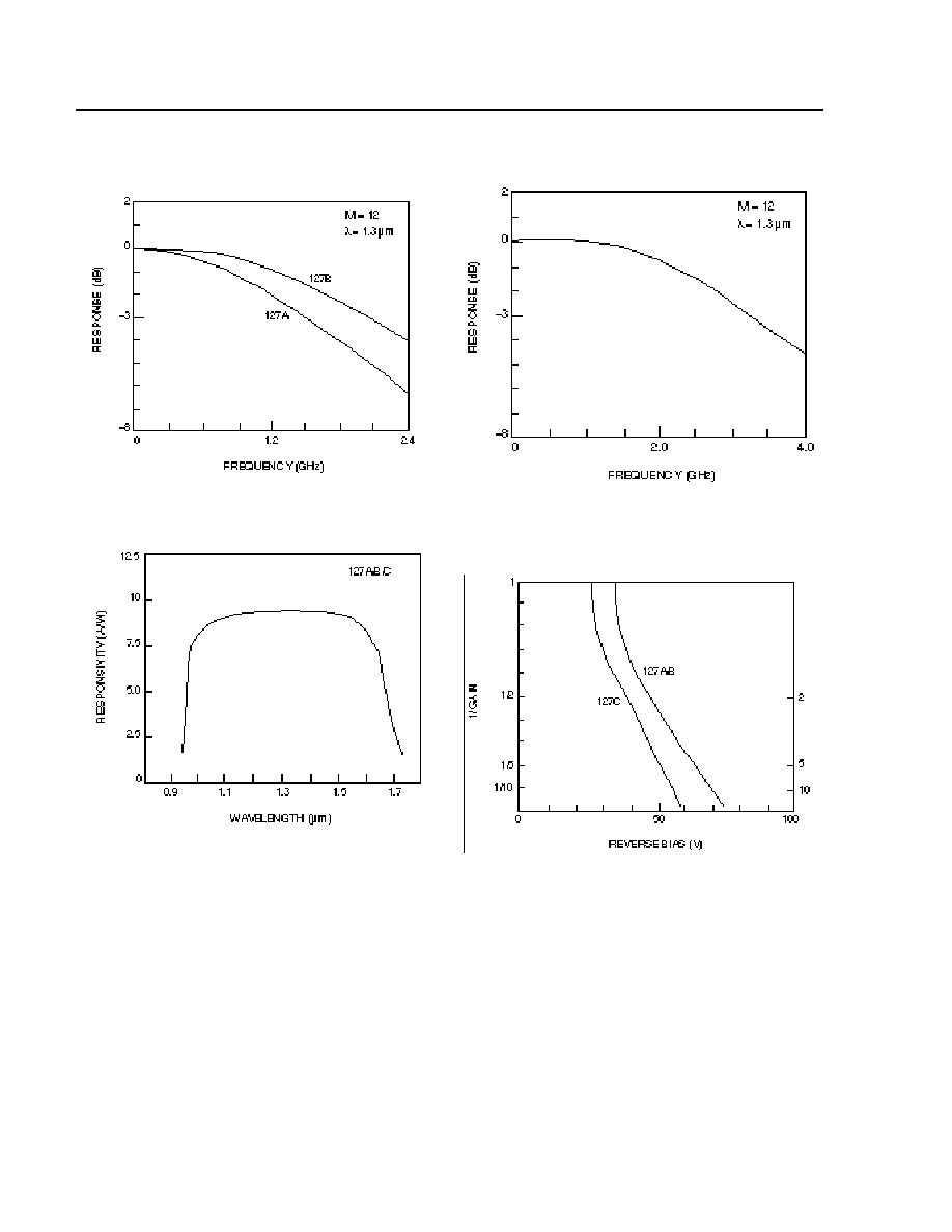
Characteristic Curves
(T
A
= 25 ∞C)
Figure 1. Frequency Response (127A/B)
Note: Responsivity = chip quantum efficiency x pigtail coupling effi-
ciency x gain x
(µm)/1.24. The minimum chip quantum effi-
ciency is 80%, and the minimum pigtail coupling efficiency is
90%.
Figure 2. Responsivity vs. Wavelength for M = 12
and
= 1.3 µm
Figure 3. Frequency Response (127C)
Figure 4. 1/Gain vs. Reverse Bias
1-589 (C)
1-586 (C)
1-587 (C)
1-588 (C)
Lucent Technologies Inc.
5
Data Sheet
September 1998
127A/B/C InGaAs Avalanche Photodetectors
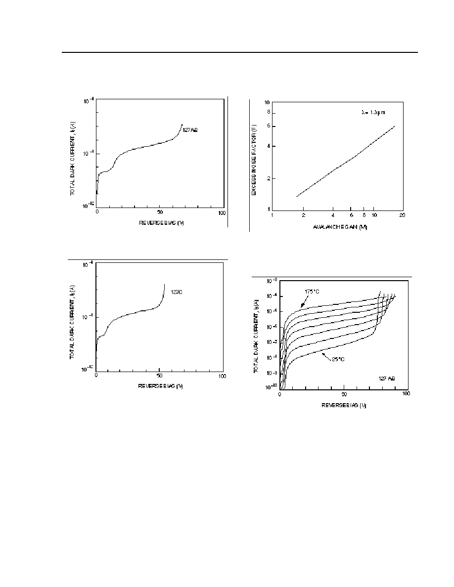
Characteristic Curves
(T
A
= 25 ∞C)
Figure 5. Dark Current vs. Reverse Bias (127A/B)
Figure 6. Dark Current vs. Reverse Bias (127C)
Figure 7. Excess Noise Factor vs. Gain
Note: The temperature dependence of the 127C dark current is the
same as the 127A/B.
Figure 8. Dark Current vs. Voltage as a Function
of Temperature at 25 ∞C Increments
1-321 (C)
1-606 (C)
1-607 (C)
1-608 (C)
(continued)
Figure 7. Excess Noise Factor vs. Gain