 | –≠–ª–µ–∫—Ç—Ä–æ–Ω–Ω—ã–π –∫–æ–º–ø–æ–Ω–µ–Ω—Ç: 1725-TYPE | –°–∫–∞—á–∞—Ç—å:  PDF PDF  ZIP ZIP |
Preliminary Data Sheet
February 2000
1725-Type Gain Block
Erbium-Doped Fiber Amplifier
Characterized by extremely flat gain over a wide 1.5 µm
wavelength range, the 1725-Type Gain Block EDFA features a
number of input and output taps for amplifier and system
diagnostics.
Features
s
High saturated output power, >14 dBm (upgrad-
able to 17 dBm and 20 dBm)
s
Wide operating wavelength range,
1530 nm--1560 nm
s
Extremely flat gain profile, <1 dB typical
s
Very low noise figure
s
Interstage access for system customization
s
Input and output monitors for easy system diagno-
sis
s
Isolated input and output ports
s
Wide operating temperature range,
≠5 ∞C to +70 ∞C
Applications
s
Designed for DWDM applications
s
In-line DWDM amplifier with interstage access for
dispersion compensating fiber (DCF), or optical
add/drop multiplexers (OADMs)
s
Bidirectional preamp and booster amplifier

2
2
Agere Systems Inc.
Preliminary Data Sheet
February 2000
Erbium-Doped Fiber Amplifier
1725-Type Gain Block
Description
The Agere Systems Inc. 1725-type gain block erbium-
doped fiber amplifier (EDFA) is a multistage gain block
specifically designed for use in high-performance
DWDM systems. This design achieves an extremely flat
gain profile over the entire 1530 nm to 1560 nm wave-
length range.
Ports are provided for access to the midstage of the
amplifier. The amplifier design can accommodate up to
9 dB of loss through these ports. This midstage access
allows the user to customize the 1725-type amplifier to
meet system needs. Typical uses for this feature include
using dispersion-compensating fiber (DCF) or optical
add/drop multiplexers (OADMs).
Another advanced feature of the 1725-type EDFA is that
the nominal output power of 14 dBm can be increased
by providing additional 1480 nm pump power. To facili-
tate this, the 1725 EDFA contains a port terminated with
an SC/APC optical connector to which an external 1480
nm pump laser module may be connected. This allows
the customer the flexibility to upgrade the output power
of the amplifier as system requirements change.
Input and output tap monitor ports are standard fea-
tures that aid the customer with amplifier and system
diagnostics. All inputs and outputs are isolated to
reduce the effects of reflections on amplifier perfor-
mance.
The device has been qualified for DWDM applications
and meets the intent of Telcordia Technologies * GR-
1312-CORE.
Pin Information
Table 1. Pin Descriptions
Pin
Description
1
Pump 1 TEC (≠)
2
Pump 1 TEC (≠)
3
Pump 1 Laser Cathode
4
Pump 1 Laser Anode
5
Pump 2 TEC (+)
6
Pump 2 TEC (+)
7
Pump 2 Thermistor (+)
8
Pump 2 Thermistor (≠)
9
Pump 2 Back-facet Monitor Cathode (+)
10
Pump 2 Back-facet Monitor Anode (≠)
11
EDFA Case
12
NC
13
Pump 1 TEC (+)
14
Pump 1 TEC (+)
15
Pump 1 Thermistor (+)
16
Pump 1 Thermistor (≠)
17
Pump 1 Back-facet Monitor Cathode (+)
18
Pump 1 Back-facet Monitor Anode (≠)
19
Pump 2 TEC (≠)
20
Pump 2 TEC (≠)
21
Pump 2 Laser Anode
22
Pump 2 Laser Cathode
1-1055(F)
Figure 1. Block Diagram
* Telcordia Technologies is a trademark of Bell Communications Research, Inc.
OPTICAL
GAIN
OPTICAL
INPUT
SIGNAL
PREAMP SECTION
OPTICAL
GAIN
BOOSTER SECTION
INTERSTAGE
(9 dB LOSS)
OPTICAL
OUTPUT
SIGNAL
PORT FOR
ADDITIONAL
PUMP POWER
INPUT
TAP
OUTPUT
TAP
INPUT
TAP
OUTPUT
TAP
OUTPUT

Agere Systems Inc.
3
Preliminary Data Sheet
February 2000
Erbium-Doped Fiber Amplifier
1725-Type Gain Block
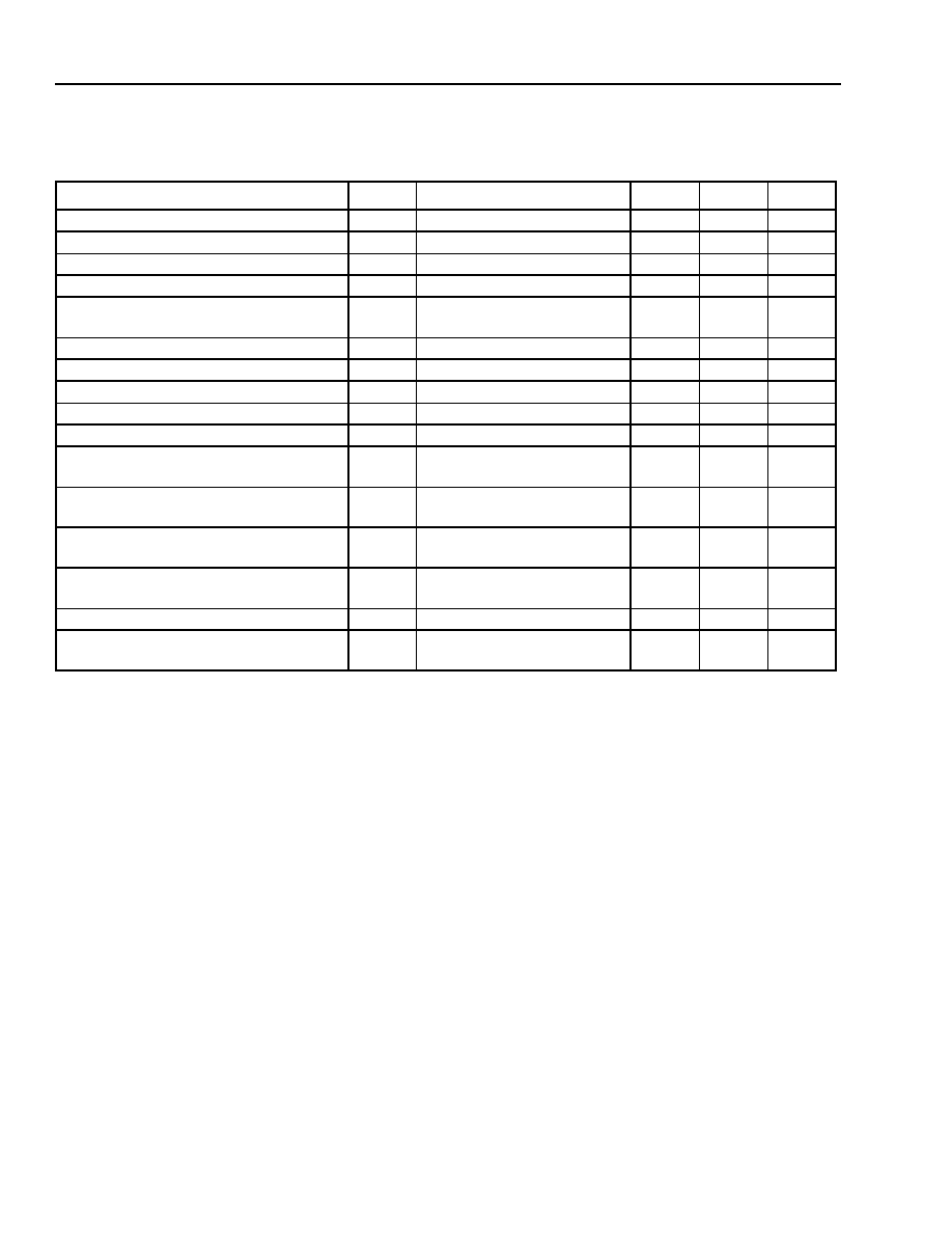
Absolute Maximum Ratings
Stresses in excess of the absolute maximum ratings can cause permanent damage to the device. These are abso-
lute stress ratings only. Functional operation of the device is not implied at these or any other conditions in excess
of those given in the operational sections of the data sheet. Exposure to absolute maximum ratings for extended
periods can adversely affect device reliability.
Optical Characteristics
Parameter
Symbol
Min
Max
Unit
Storage Temperature
T
stg
≠40
85
∞C
Operating Temperature
T
OP
≠5
70
∞C
Bias Current First-stage Pump
I
BS1
--
400
mA
Bias Current Second-stage Pump
I
BS2
--
800
mA
Pump Laser Reverse Voltage
V
R
--
2
V
TEC Current First-stage Pump
I
TECS1
--
1.5
A
TEC Current Second-stage Pump
I
TECS2
--
1.6
A
Monitor Reverse Bias Voltage
V
RMON
--
10
V
Temperature Sensor Current
T
SEN
--
5
mA
Table 2a. Performance Specifications
Parameter
Symbol
Conditions
Min
Max
Unit
Wavelength Range
--
1530.3
1560.6
nm
EOL Optical Output Power
P
OUT
P
IN
= ≠14 dBm
14
--
dBm
Gain Flatness
GF
P
IN
= ≠14 dBm,
9 dB interstage loss
--
1.5
dB
Noise Figure
NF
P
IN
= ≠14 dBm
--
6.0
dB
First-stage Pump Bias
I
F1
--
--
330
mA
Second-stage Pump Bias
I
F2
--
--
800
mA
First-stage Pump Forward Voltage
I
VF1
--
--
2.5
V
Second-stage Pump Forward Voltage
I
VF2
--
--
2.5
V
First-stage Pump TEC Current
I
TEC1
Case temperature = 70 ∞C,
bias currents = EOL values
--
1.5
A
Second-stage Pump TEC Current
I
TEC2
Case temperature = 70 ∞C,
bias currents = EOL values
--
1.5
A
First-stage Pump TEC Voltage
V
TEC1
Case temperature = 70 ∞C,
bias currents = EOL values
--
3.0
V
Second-stage Pump TEC Voltage
V
TEC2
Case temperature = 70 ∞C,
bias currents = EOL values
--
4.0
V
First-stage Pump Photodetector Current
I
PD1
--
270
2500
µA
Second-stage Pump Photodetector
Current
I
PD2
--
100
2250
µA
4
Agere Systems Inc.
Preliminary Data Sheet
February 2000
Erbium-Doped Fiber Amplifier
1725-Type Gain Block
Optical Characteristics
(continued)
Table 2b. Performance Specifications (Enhanced 17 dBm Version)
Parameter
Symbol
Conditions
Min
Max
Unit
Wavelength Range
--
1530.3
1560.6
nm
EOL Optical Output Power
P
OUT
P
IN
= ≠11 dBm
17
--
dBm
Optical Power from External Pump
--
--
--
120
mW
Center Wavelength for External Pump
--
--
1460
1488
nm
Gain Flatness
GF
P
IN
= ≠11 dBm,
9 dB interstage loss
--
1.5
dB
Noise Figure
NF
P
IN
= ≠11 dBm
--
6.25
dB
First-stage Pump Bias
I
F1
--
--
330
mA
Second-stage Pump Bias
I
F2
--
--
800
mA
First-stage Pump Forward Voltage
I
VF1
--
--
2.5
V
Second-stage Pump Forward Voltage
I
VF2
--
--
2.5
V
First-stage Pump TEC Current
I
TEC1
Case temperature = 70 ∞C,
bias currents = EOL values
--
1.5
A
Second-stage Pump TEC Current
I
TEC2
Case temperature = 70 ∞C,
bias currents = EOL values
--
1.5
A
First-stage Pump TEC Voltage
V
TEC1
Case temperature = 70 ∞C,
bias currents = EOL values
--
3.0
V
Second-stage Pump TEC Voltage
V
TEC2
Case temperature = 70 ∞C,
bias currents = EOL values
--
4.0
V
First-stage Pump Photodetector Current
I
PD1
--
270
2500
µA
Second-stage Pump Photodetector
Current
I
PD2
--
100
2250
µA

Agere Systems Inc.
5
Preliminary Data Sheet
February 2000
Erbium-Doped Fiber Amplifier
1725-Type Gain Block
Optical Characteristics
(continued)
Table 2c. Performance Specifications (Enhanced 20 dBm Version)
Parameter
Symbol
Conditions
Min
Max
Unit
Wavelength Range
--
1530.3
1560.6
nm
EOL Optical Output Power
P
OUT
P
IN
= ≠8 dBm
20
--
dBm
Optical Power from External Pump
--
--
--
330
mW
Center Wavelength for External Pump
--
--
1460
1488
nm
Gain Flatness
GF
P
IN
= ≠8 dBm,
9 dB interstage loss
--
1.5
dB
Noise Figure
NF
P
IN
= ≠8 dBm
--
7.0
dB
First-stage Pump Bias
I
F1
--
--
330
mA
Second-stage Pump Bias
I
F2
--
--
800
mA
First-stage Pump Forward Voltage
I
VF1
--
--
2.5
V
Second-stage Pump Forward Voltage
I
VF2
--
--
2.5
V
First-stage Pump TEC Current
I
TEC1
Case temperature = 70 ∞C,
bias currents = EOL values
--
1.5
A
Second-stage Pump TEC Current
I
TEC2
Case temperature = 70 ∞C,
bias currents = EOL values
--
1.5
A
First-stage Pump TEC Voltage
V
TEC1
Case temperature = 70 ∞C,
bias currents = EOL values
--
3.0
V
Second-stage Pump TEC Voltage
V
TEC2
Case temperature = 70 ∞C,
bias currents = EOL values
4.0
V
First-stage Pump Photodetector Current
I
PD1
--
270
2500
µA
Second-stage Pump Photodetector
Current
I
PD2
--
100
2250
µA
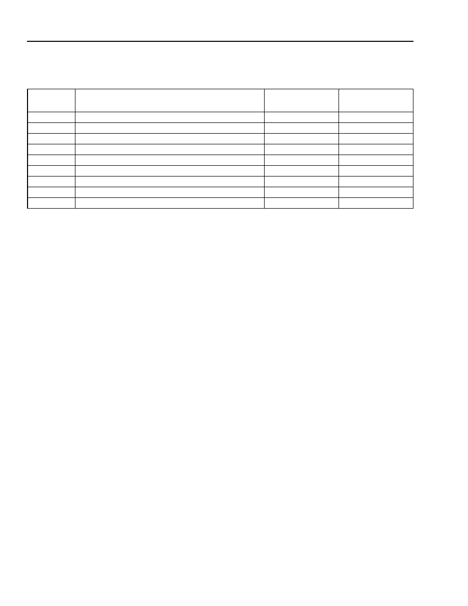
Table 3. Input/Output Monitor Specifications
Parameter
Min
Max
Unit
Wavelength Range
1530.3
1560.6
nm
First-stage Input Monitoring Loss
11.5
14.5
dB
First-stage Output Monitoring Loss
11.5
14.5
dB
Second-stage Input Monitoring Loss
11.5
14.5
dB
Second-stage Output Monitoring Loss
18.0
22.0
dB
6
Agere Systems Inc.
Preliminary Data Sheet
February 2000
Erbium-Doped Fiber Amplifier
1725-Type Gain Block
Fiber Scheme
Table 4. Fiber Scheme
Fiber Color
Description
Connector
Length
(inches)
Blue
EDFA Input Port
SC/PC
32 +1.5/≠1.0
Orange
Output to Preamp-stage Port (input to interstage)
SC/PC
32 +1.5/≠1.0
Green
Input to Booster-stage Port (output from interstage)
SC/PC
32 +1.5/≠1.0
Red
EDFA Output Port
SC/PC
32 +1.5/≠1.0
Black
Input Monitor Port
SC/PC
32 +1.5/≠1.0
Gray
Preamp-stage Output Monitor Port
SC/PC
32 +1.5/≠1.0
Brown
Booster-stage Input Monitor Port
SC/PC
32 +1.5/≠1.0
Yellow
Additional Pump Power Port
SC/APC
36 +1.5/≠1.0
White
EDFA Output Monitor Port
SC/PC
32 +1.5/≠1.0

Agere Systems Inc.
7
Preliminary Data Sheet
February 2000
Erbium-Doped Fiber Amplifier
1725-Type Gain Block
Outline Drawings
1725-Type Gain Block EDFA Package
Dimensions are in inches and (millimeters).
3.622
(
9
2
.
00)
3.937
(
100
.00)
3.484 (88.48)
4.921 (125.00)
4.606 (117.00)
2.976 (
75.59)
2.520
(
6
4
.
01)
0
.
551 (
14.00)
1
.
438 (
36.53)
0
.
994 (
25.25)
(EXTERNAL PUMP NOT INCLUDED)
0.750
(19.05)
0.175
±
0.020
(4.45
±
0.50)
0.438 (11.13)
1-1053(F)
8
Agere Systems Inc.
Preliminary Data Sheet
February 2000
Erbium-Doped Fiber Amplifier
1725-Type Gain Block
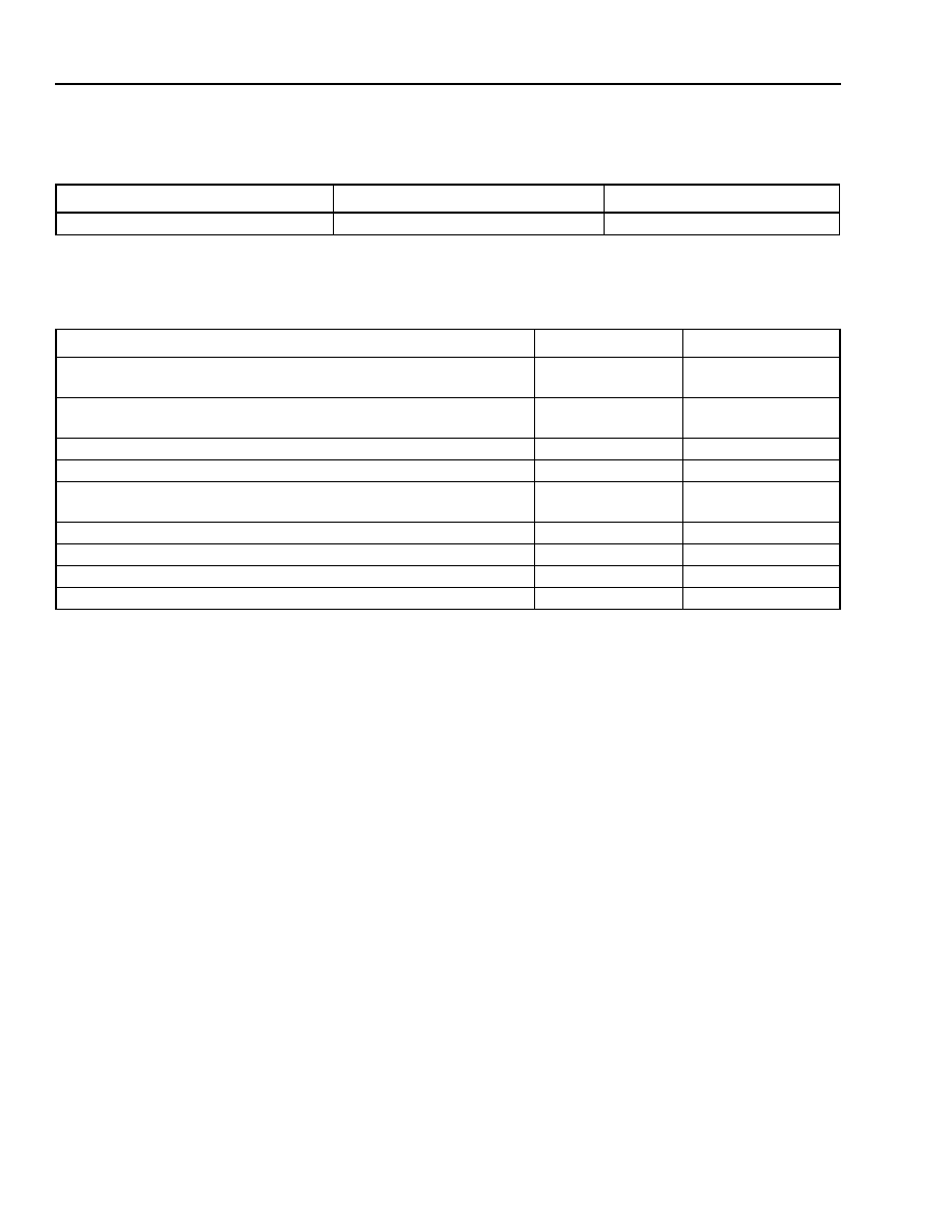
Ordering Information
Table 5. Ordering Information
Related Product Information
Description
Device Code
Comcode
Gain Block EDFA
1725-Type
TBD
Table 6. Related Product Information
Description
Part Number
Document Number
Optical Amplifier Platform, 1724-Type Erbium-Doped Fiber Amplifier
(S and V Series)
S1724-Type
V1724-Type
DS99-259LWP
Optical Amplifier Platform, 1724-Type Erbium-Doped Fiber Amplifier
(W Series)
W1724-Type
DS00-123OPTO
Optical Amplifier Platform, 1730-Type Erbium-Doped Fiber Amplifier
1730-Type
DS99-353LWP
Extended Band (L-Band) 1735-Type Erbium-Doped Fiber Amplifier
1735-Type
DS00-113OPTO
Interfacing the 1724-Type Microprocessor-Controlled Erbium-Doped
Fiber Amplifier via a Serial Communication Port
1724-Type
AP99-020LWP
High-Speed 2.5 Gbits/s Lightwave Receiver
1319-Type
DS97-106LWP
1.5 µm Isolated DFB Laser Module
D2500-Type
DS98-339LWP
1.3 µm Isolated DFB Laser Module
D2300-Type
DS97-122LWP
2.5 Gbits/s Lightwave Receiver with Clock Recovery
1320-Type
DS97-113LWP
Agere Systems Inc.
9
Preliminary Data Sheet
February 2000
Erbium-Doped Fiber Amplifier
1725-Type Gain Block
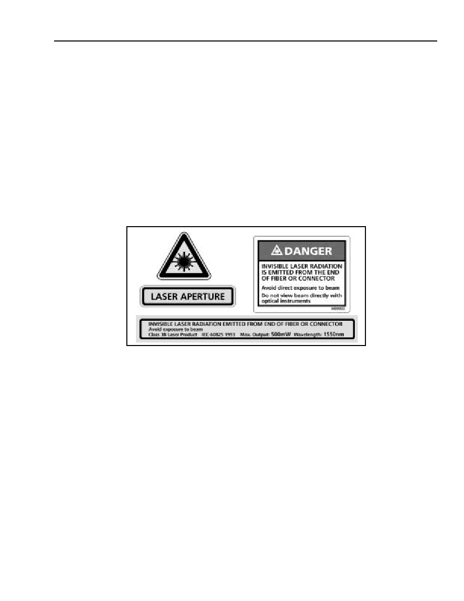
Laser Safety Information
Class IIIb Laser Product
FDA/CDRH Class IIIb laser products. All versions of the device are Class IIIb laser products per CDRH, 21 CFR
1040 Laser Safety requirements. All versions are Class IIIb laser products per IEC
* 60825-1:1993. The devices
have been certified with the FDA under accession number 9320325.
This product complies with 21 CFR 1040.10 and 1040.11.
8.8/125 µm single-mode fiber pigtail with connector
Wavelength = 1.5
µ
m
Maximum power = 500 mW
Product is not shipped with power supply.
CAUTION: Use of controls, adjustments, and procedures other than those specified herein may result in
hazardous laser radiation exposure.
* IEC is a registered trademark of The International Electrotechnical Commission.
500 mW
1.5
µ
m

Agere Systems Inc. reserves the right to make changes to the product(s) or information contained herein without notice. No liabi lity is assumed as a result of their use or application.
Copyright © 2001 Agere Systems Inc.
All Rights Reserved
February 2000
DS99-271LWP-1 (Replaces DS99-271LWP)
For additional information, contact your Agere Systems Account Manager or the following:
INTERNET:
http://www.agere.com
E-MAIL:
docmaster@agere.com
N. AMERICA:
Agere Systems Inc., 555 Union Boulevard, Room 30L-15P-BA, Allentown, PA 18109-3286
1-800-372-2447, FAX 610-712-4106 (In CANADA: 1-800-553-2448, FAX 610-712-4106)
ASIA:
Agere Systems Hong Kong Ltd., Suites 3201 & 3210-12, 32/F, Tower 2, The Gateway, Harbour City, Kowloon
Tel. (852) 3129-2000, FAX (852) 3129-2020
CHINA: (86) 21-5047-1212 (Shanghai), (86) 10-6522-5566 (Beijing), (86) 755-695-7224 (Shenzhen)
JAPAN: (81) 3-5421-1600 (Tokyo), KOREA: (82) 2-767-1850 (Seoul), SINGAPORE: (65) 778-8833, TAIWAN: (886) 2-2725-5858 (Taipei)
EUROPE:
Tel. (44) 7000 624624, FAX (44) 1344 488 045