 | –≠–ª–µ–∫—Ç—Ä–æ–Ω–Ω—ã–π –∫–æ–º–ø–æ–Ω–µ–Ω—Ç: 269 | –°–∫–∞—á–∞—Ç—å:  PDF PDF  ZIP ZIP |

269-Type 1480 nm Pump Laser Module
Data Sheet
June 2001
The 269-type pump laser module is designed as a continuous-
wave (CW) optical pump source for erbium-doped fiber ampli-
fiers.
Features
s
High-coupled rated output power up to 280 mW,
CW
s
Wide environmental range
s
Field-proven packaging technology
s
InGaAsP/InP high-power, strained multiple quan-
tum-well (MQW) chip design
s
Internal optical isolator (optional)
s
Internal thermoelectric cooler (TEC)
s
InGaAs PIN photodetector back-facet monitor
s
Single-mode and polarization-maintaining fiber pig-
tails
s
Compact, 14-pin butterfly package
s
Industry compatible package and pinout
Applications
s
Erbium-doped fiber amplifiers (EDFA)
Description
The 269-type pump laser module represents a family
of thermoelectrically cooled, high-power lasers. They
are designed as continuous-wave (CW) optical pump
sources for dense wavelength-division multiplexing
(DWDM) EDFA applications.
The laser modules incorporate a high-power, quan-
tum-well laser chip that achieves fiber powers up to
280 mW.
An integral thermoelectric cooler (TEC) stabilizes the
laser at room temperature and, combined with a her-
metic environment, allows the device to achieve
high-power operation over the extended temperature
range of 0 ∞C to 75 ∞C. An internal InGaAs PIN pho-
todiode, mounted behind the laser diode, functions
as the laser detector and monitors light emissions
from the rear facet of the laser.
The 269-type module is offered in a 14-pin, hermetic
butterfly package.

Data Sheet
269-Type 1480 nm Pump Laser Module
June 2001
2
Agere Systems Inc.
Absolute Maximum Ratings
Stresses in excess of the absolute maximum ratings can cause permanent damage to the device. These are abso-
lute stress ratings only. Functional operation of the device is not implied at these or any other conditions in excess
of those given in the operational sections of the data sheet. Exposure to absolute maximum ratings for extended
periods can adversely affect device reliability.
Handling Precautions
Electrostatic Discharge
CAUTION: This device is susceptible to damage as a result of electrostatic discharge (ESD). Take proper
precautions during both handling and testing. Follow guidelines such as
EIA
* Standard
EIA
625.
Agere Systems Inc. employs a human-body model (HBM) for ESD-susceptibility testing and protection-design eval-
uation. ESD voltage thresholds are dependent on the critical parameters used to define the model. A standard
HBM (resistance = 1.5 k
, capacitance = 100 pF) is widely used and, therefore, can be used for comparison pur-
poses. The HBM ESD withstand voltage established for the 269-type laser pump module is ±500 V.
*
EIA
is a registered trademark of The Electronic Industries Association.
Parameter
Symbol
Min
Max
Unit
Operating Case Temperature Range
T
C
0
75
∞C
Storage Case Temperature Range
T
stg
≠40
85
∞C
Laser Forward Bias (TEC on):
P
O
= 120 mW--150 mW
P
O
= 160 mW--210 mW
P
O
= 220 mW--280 mW
I
F
--
--
--
1000
1500
1900
mA
mA
mA
Laser Reverse Voltage
V
R
--
2
V
Photodiode Reverse Voltage
V
RMON
--
20
V
TEC Current
I
TEC
--
2.2
A
TEC Voltage
V
TEC
--
5.0
V
Temperature Sensor Current
I
TS
--
5
mA
Laser Diode Operating Chip Temperature
T
LD
--
40
∞C

Data Sheet
June 2001
269-Type 1480 nm Pump Laser Module
3
Agere Systems Inc.
Electrical/Optical Characteristics
Table 1. Electrical/Optical Characteristics (All performance parameters are specified for I
F, OP
, T
SET
= 25 ∞C,
T
CASE
~ 25 ∞C, unless otherwise specified.)
Parameter
Symbol
Conditions
Min
Typ
Max
Unit
Operating Optical Power
P
O
--
120
--
280
mW
Center Wavelength
C
--
1465
1480
1490
nm
RMS Spectral Width
P
O
--
4
10
nm
BOL Operating Laser Forward Current:
P
O
= 120 mW
P
O
= 130 mW
P
O
= 140 mW
P
O
= 150 mW
I
F, OP BOL
--
--
--
--
--
--
--
--
--
--
--
--
550
600
600
600
mA
mA
mA
mA
BOL Operating Laser Forward Current:
P
O
= 160 mW
P
O
= 170 mW
P
O
= 180 mW
P
O
= 190 mW
P
O
= 200 mW
I
F, OP BOL
--
--
--
--
--
--
--
--
--
--
--
--
--
--
--
650
700
700
750
800
mA
mA
mA
mA
mA
BOL Operating Laser Forward Current:
P
O
= 210 mW
P
O
= 220 mW
P
O
= 230 mW
P
O
= 240 mW
P
O
= 250 mW
P
O
= 260 mW
P
O
= 270 mW
P
O
= 280 mW
I
F, OP BOL
--
--
--
--
--
--
--
--
--
--
--
--
--
--
--
--
--
--
--
--
--
--
--
--
850
900
950
1000
1000
1100
1100
1100
mA
mA
mA
mA
mA
mA
mA
mA
EOL Operating Laser Forward Current
I
F, OP EOL
--
--
--
1.15 x
I
F, OP BOL
mA
EOL Laser Diode Forward Voltage
V
R
I
F, OP
EOL
--
2.3
3.0
V
Module Optical Isolation
(optional feature)
ISO
EOL Over
T
CASE RANGE
30
--
--
dB
Polarization Extinction Ratio
PER
--
13
--
--
dB
Table 2. Monitor Photodiode Characteristics (All test parameters are specified for I
F, OP,
T
SET
= 25 ∞C,
T
CASE
~ 25 ∞C unless otherwise specified.)
Parameter
Symbol
Conditions
Min
Max
Unit
Monitor Diode Current
I
BF
--
200
2000
µ
A
Monitor Diode Dark Current
I
D
V
R
= ≠5 V, I
F
= 0
--
100
nA

Data Sheet
269-Type 1480 nm Pump Laser Module
June 2001
4
Agere Systems Inc.
Electrical/Optical Characteristics
(continued)
Table 3. TEC and Thermistor Characteristics (All performance parameters are specified for I
F, OP,
T
SET
= 25 ∞C,
unless otherwise specified.)
Parameter
Symbol
Conditions
Min
Max
Unit
TEC Current:
P
O
= 120 mW
P
O
= 130 mW
P
O
= 140 mW
P
O
= 150 mW
I
TEC
T
SET
= 25 ∞C;
T
CASE
= 75 ∞C;
T = 50 ∞C, EOL
--
--
--
--
1.6
1.6
1.6
1.6
A
A
A
A
TEC Current:
P
O
= 160 mW
P
O
= 170 mW
P
O
= 180 mW
P
O
= 190 mW
P
O
= 200 mW
I
TEC
T
SET
= 25 ∞C;
T
CASE
= 70 ∞C;
T = 45 ∞C, EOL
--
--
--
--
--
1.7
1.7
1.7
1.7
1.7
A
A
A
A
A
TEC Current:
P
O
= 210 mW
P
O
= 220 mW
P
O
= 230 mW
P
O
= 240 mW
P
O
= 250 mW
P
O
= 260 mW
P
O
= 270 mW
P
O
= 280 mW
I
TEC
T
SET
= 25 ∞C;
T
CASE
= 65 ∞C;
T = 40 ∞C, EOL
--
--
--
--
--
--
--
--
2.0
2.0
2.0
2.0
2.0
2.0
2.0
2.0
A
A
A
A
A
A
A
A
TEC Voltage:
P
O
= 120 mW
P
O
= 130 mW
P
O
= 140 mW
P
O
= 150 mW
V
TEC
T
SET
= 25 ∞C;
T
CASE
= 75 ∞C;
T = 50 ∞C, EOL
--
--
--
--
3.5
3.5
3.5
3.5
V
V
V
V
TEC Voltage:
P
O
= 160 mW
P
O
= 170 mW
P
O
= 180 mW
P
O
= 190 mW
P
O
= 200 mW
V
TEC
T
SET
= 25 ∞C;
T
CASE
= 70 ∞C;
T = 45 ∞C, EOL
--
--
--
--
--
3.7
3.7
3.7
3.7
3.7
V
V
V
V
V
TEC Voltage:
P
O
= 210 mW
P
O
= 220 mW
P
O
= 230 mW
P
O
= 240 mW
P
O
= 250 mW
P
O
= 260 mW
P
O
= 270 mW
P
O
= 280 mW
V
TEC
T
SET
= 25 ∞C;
T
CASE
= 65 ∞C;
T = 40 ∞C, EOL
--
--
--
--
--
--
--
--
4.2
4.2
4.2
4.2
4.2
4.2
4.2
4.2
V
V
V
V
V
V
V
V
Thermistor Resistance
R
THERM
25 ∞C Laser Diode
Set Temperature
9.5
10.5
k
Themistor B Constant
B
--
3700
4100
K
Data Sheet
June 2001
269-Type 1480 nm Pump Laser Module
5
Agere Systems Inc.
User Information
* A positive input into this pin cools the laser.
Fiber Characteristics
s
Length of fiber pigtail:
-- 1.75 m ± 0.25 m
s
Standard fiber:
-- Cladding OD: 125
µ
m ± 2
µ
m
-- Acrylate buffer OD: 250
µ
m ± 15
µ
m
-- Cut off wavelength: <1320 nm
s
Polarization-maintaining fiber:
-- PANDA
-- Cut off wavelength: <1400 nm
-- Acrylate buffer: 400
µ
m
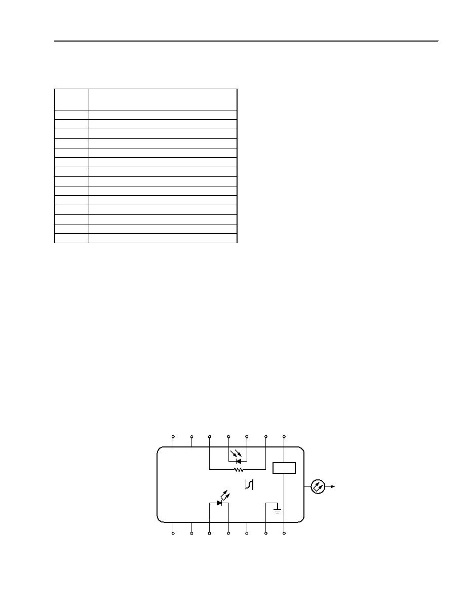
Table 4. Pin Information
Pin
Number
Connection
1
TE Cooler (+)*
2
Thermistor
3
Monitor Anode (≠Bias)
4
Monitor Cathode (+Bias)
5
Thermistor
6
No Connect
7
No Connect
8
No Connect
9
No Connect
10
Laser Anode (+)
11
Laser Cathode (≠)
12
No Connect
13
Package Ground
14
TEC Cooler (≠)
Mounting and Connections
CAUTION: This device is susceptible to damage as
a result of electrostatic discharge.
Proper precautions should be taken
during both handling and testing.
The base of the laser module (see Outline Diagram)
should be maintained at or below 75 ∞C (maximum)
during operation. Interfaces between the laser module
base and heat sink must be clean, and the use of a
thermal filler may be necessary.
Mounting Instructions
The minimum fiber bend radius is 1.0 in.
To avoid degradation in performance, mount the mod-
ule on the board as follows:
1. Place the bottom flange of the module on a flat heat
sink at least 0.5 in. x 1.180 in. (12.7 mm x 30 mm)
in size. The surface finish of the heat sink should be
better than 32
µ
in. (0.8
µ
m), and the surface flat-
ness must be better than 0.001 in. (25.4
µ
m). Using
thermal conductive grease is optional; however,
thermal performance may be improved if conductive
grease is applied between the bottom flange and
the heat sink.
2. Mount four #2-56 screws with Fillister heads
(M2-3 mm) at the four screw hole locations (see
Outline Diagram). The Fillister head diameter must
not exceed 0.140 in. (3.55 mm). Do not apply more
than 1 in./lb. of torque to the screws.
Figure 1. Circuit Schematic
1-675 (F).i
7
6
5
4
3
2
1
8
9
10
11
12
13
14
TH 10 k
TEC
ISOLATOR
≠
+
+
≠
(OPTIONAL)