 | –≠–ª–µ–∫—Ç—Ä–æ–Ω–Ω—ã–π –∫–æ–º–ø–æ–Ω–µ–Ω—Ç: A370-TYPE | –°–∫–∞—á–∞—Ç—å:  PDF PDF  ZIP ZIP |
Data Sheet
March 2001
A370-Type Analog
Uncooled Laser Module
The low-profile A370-Type Analog Laser Module is ideally
suited for CATV applications, particularly in systems where
long spans and superior reliability are the critical consider-
ations
.
Features
s
Eight-pin package suitable for CATV
applications
s
Frequency range up to 1.0 GHz
s
MQW F-P 1.3
µ
m laser with single-mode fiber
pigtail
s
Wide operating temperature range:
≠40
∞
C to +85
∞
C
s
No TEC required
s
High output power: typically 1.0 mW power cou-
pled into single-mode fiber
s
Hermetically sealed active components
s
Internal back-facet monitor
s
Qualification program:
Telcordia Technologies
*
TA-983
Applications
s
Narrowband video
s
Downstream telephony and data
s
Return path systems
s
Analog and digital modulation systems
s
Telecommunications
Benefits
s
Easily board mounted
s
Requires no lead bending
s
No additional heat sinks required
s
Pin compatible with industry-standard, 14-pin
laser module
s
High output power allows for longer system spans,
more fiber splits, and greater tolerance of fiber and
connector quality
*
Telcordia Technologies
is a trademark of Telcordia Technologies,
Inc.
A370-Type Analog
Data Sheet
Uncooled Laser Module
March 2001
2
2
Lucent Technologies Inc.
Description
The A370-Type Uncooled Laser Module consists of a
laser diode coupled to a single-mode fiber pigtail. The
device is available in a standard, 8-pin configuration
(see Figure 1 and/or Table 1) and is ideal for CATV
applications.
The module includes a multiquantum-well Fabry-Perot
(MQW F-P) laser and an InGaAs PIN photodiode back-
facet monitor in an epoxy-free, hermetically sealed
package.
The device characteristics listed in this document are
met at 1.0 mW output power. Higher- or lower-power
operation is possible. Under conditions of a fixed pho-
todiode current, the change in optical output is typically
±
0.5 dB over an operating temperature range of ≠40
∞
C
to +85
∞
C.
This device incorporates the new Laser 2000 manufac-
turing process from the Optoelectronics unit of Lucent
Technologies Microelectronics Group. Laser 2000 is a
low-cost platform that targets high-volume manufactur-
ing and tight product distributions on all optical sub-
assemblies. This platform incorporates an advanced
optical design that is produced on the Optoelectronic
unit's highly automated production lines. The Laser
2000 platform is qualified for the central office and
uncontrolled environments, and can be used for appli-
cations requiring high performance and low cost.
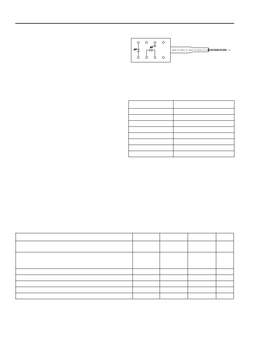
Figure 1. A370-Type Analog Uncooled Laser
Module Schematic, Top View
Table 1. Pin Descriptions
Pin Number
Connection
1
NC
2
Case ground
3
NC
4
Photodiode cathode
5
Photodiode anode
6
Laser diode cathode
7
Laser diode anode
8
NC
1-900 (C)
5
6
8
7
4
3
1
2
Absolute Maximum Ratings
Stresses in excess of the absolute maximum ratings can cause permanent damage to the device. These are abso-
lute stress ratings only. Functional operation of the device is not implied at these or any other conditions in excess
of those given in the operations sections of the data sheet. Exposure to absolute maximum ratings for extended
periods can adversely affect device reliability.
* Rating varies with temperature.
Parameter
Symbol
Min
Max
Unit
Maximum Peak Laser Drive Current or
Maximum Fiber Power*
I
OP
P
MAX
--
--
150
10
mA
mW
Peak Reverse Laser Voltage:
Laser
Monitor
V
RL
V
RD
--
--
2
20
V
V
Monitor Forward Current
I
FD
--
2
mA
Operating Case Temperature Range
T
C
≠40
85
∞
C
Storage Case Temperature Range
T
stg
≠40
85
∞
C
Lead Soldering Temperature/Time
--
--
260/10
∞
C/s
Relative Humidity (noncondensing)
RH
--
85
%

Data Sheet
A370-Type Analog
March 2001
Uncooled Laser Module
3
Lucent Technologies Inc.
Handling Precautions
Caution: This device is susceptible to damage as a result of electrostatic discharge (ESD). Take proper pre-
cautions during both handling and testing. Follow guidelines such as JEDEC Publication No.
108-A (Dec. 1988).
Although protection circuitry is designed into the device, take proper precautions to avoid exposure to ESD.
Electro/Optical Characteristics
* See Table 5 for more information.
V
R
= reverse voltage.
Table 2. Electro/Optical Characteristics
(over operating temperature range unless otherwise noted)
Parameter
Symbol
Test Conditions
Min
Typ
Max
Unit
Operating Temperature
Range
T
--
≠40
--
85
∞
C
Optical Output Power*
P
F
CW, nominal
--
1
--
mW
Threshold Current
I
TH
T = 25
∞
C
T = full range
4.5
1
9
--
15
45
mA
mA
Drive Current Above
Threshold
I
MOD
CW, P
F
= 1.0 mW, T = 25
∞
C
CW, I
MON
= constant,
T = full range
20
15
30
--
40
70
mA
mA
Slope Efficiency
SE
CW, P
F
= 1.0 mW, T = 25
∞
C
25
--
50
µ
W/mA
Center Wavelength
C
P
F
= 1.0 mW, CW
1270
--
1350
nm
RMS Spectral Width
P
F
= 1.0 mW
--
2
3
nm
Tracking Error
TE
I
MON
= constant, CW
--
0.5
±
1
dB
Forward Voltage
V
F
CW
--
1.1
1.6
V
Input Impedance
R
--
3
--
8
Monitor Current
I
MON
V
R
= 5 V
400
--
1200
µ
A
Monitor Dark Current
I
D
V
R
= 5 V
--
10
200
nA
Wavelength Temperature
Coefficient
--
--
--
0.4
0.5
nm/
∞
C

A370-Type Analog
Data Sheet
Uncooled Laser Module
March 2001
4
Lucent Technologies Inc.
Electro/Optical Characteristics
(continued)
Analog Operation
The A370 Series Laser Module has the capability of being used in a wide variety of analog operations. These may
include several channels of pure video signals, or a mix of video signals with digital data channels riding on analog
carriers. It is difficult to prepare a single battery of testing conditions that will satisfy all applications. The following
table contains a set of testing conditions that Lucent believes will give a broad indication of the performance of the
A370 Series Laser Module. Please contact your local Field Application Engineer if different testing conditions and
parametric limits are required.
The distortion characteristics are measured using a two-tone test. The frequencies are 13 MHz and 19 MHz. The
second-order distortion components are measured at f1 + f2 = 32 MHz and f1 ≠ f2 = 6 MHz. All third-order distor-
tion components are measured in the frequency range of 5 MHz--200 MHz, and they meet the required level. All
measurements are made with SC-SPC connectors on the laser module pigtails.
* See Table 5 for more information.
Premium performance.
Table 3. Analog Characteristics
Parameter
Symbol
Test Conditions
Min
Typ
Max
Unit
Output Power*
P
O
CW, T = ≠40
∞
C to +85
∞
C
--
1.0
--
mW
Relative Intensity Noise
RIN
CW,
Freq. = 5 MHz to 300 MHz;
no fiber loss, T = ≠40
∞
C to +85
∞
C
--
≠140
≠130
dB/Hz
Modulation Bandwidth
BW
≠3 dB,
T = ≠40
∞
C to +85
∞
C
1.0
--
--
GHz
Second-order Distortions
--
T = 25
∞
C, OMI = 0.2;
Two-tone test: f1 = 13 MHz,
f2 = 19 MHz; 20 km of fiber,
(7 dB loss) plus connector loss,
f1
±
f2
--
≠48
≠50
≠40
≠45
dBc
dBc
Third-order Distortions
--
T = 25
∞
C, OMI = 0.2;
Two-tone test: f1 = 13 MHz,
f2 = 19 MHz; 20 km of fiber
(7 dB loss), plus connector loss,
all peaks from 5 MHz--50 MHz
meet this level
--
≠60
≠60
≠50
≠50
dBc
dBc
RF Bandpass Flatness
B
P
F
Peak to valley: 5 MHz to 200 MHz
--
--
1.0
dB
Spurious Noise
N
SP
T = 25
∞
C, OMI = 0.2;
ref. to one-tone: 5 MHz to 50 MHz,
20 km of fiber, (7 dB loss) plus
connector loss
--
≠58
≠58
≠54
≠54
dBc
dBc
Spurious Noise (carrier off)
N'
SP
T = 25
∞
C
--
≠45
≠45
≠37
≠40
dBc
dBc
Data Sheet
A370-Type Analog
March 2001
Uncooled Laser Module
5
Lucent Technologies Inc.
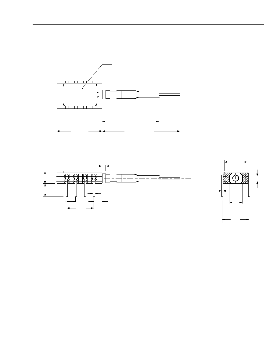
Outline Diagram
Dimensions are in inches and (millimeters).
0.010
(0.254)
0.30
(7.62)
0.29
(7.37)
0.085
(2.16)
0.17
(4.32)
0.20 (5.00)
0.165 (4.20)
0.016 (0.410)
0.100 (2.54)
0.300
(7.62)
0.110 (2.79)
0.045 (1.143)
4
3
2
1
5
6
7
8
39.37 (1000) MIN
PIGTAIL LENGTH
0.52 (13.2)
1.06 (27.0)
MIN
TRADEMARK, CODE, LASER SERIAL NUMBER,
AND/OR DATE CODE IN APPROXIMATE AREA SHOWN
1-899.f