 | –≠–ª–µ–∫—Ç—Ä–æ–Ω–Ω—ã–π –∫–æ–º–ø–æ–Ω–µ–Ω—Ç: A371-TYPE | –°–∫–∞—á–∞—Ç—å:  PDF PDF  ZIP ZIP |
Document Outline
- Features
- Applications
- Benefits
- Description
- Absolute Maximum Ratings
- Handling Precautions
- Electro/Optical Characteristics
- Analog Operation
- Outline Diagram
- Qualification Information
- Laser Safety Information
- Ordering Information
- List of Figures
- Figure 1. A371-Type Analog Uncooled Isolated DFB Laser Module Schematic, Top View
- List of Tables
- Table 1. Pin Descriptions
- Table 2. Electro/Optical Characteristics
- Table 3. Analog Characteristics
- Table 4. A371-Type Laser Module Qualification Test Plan
- Table 5. Ordering Information
- Contact Us
Data Sheet
January 1999
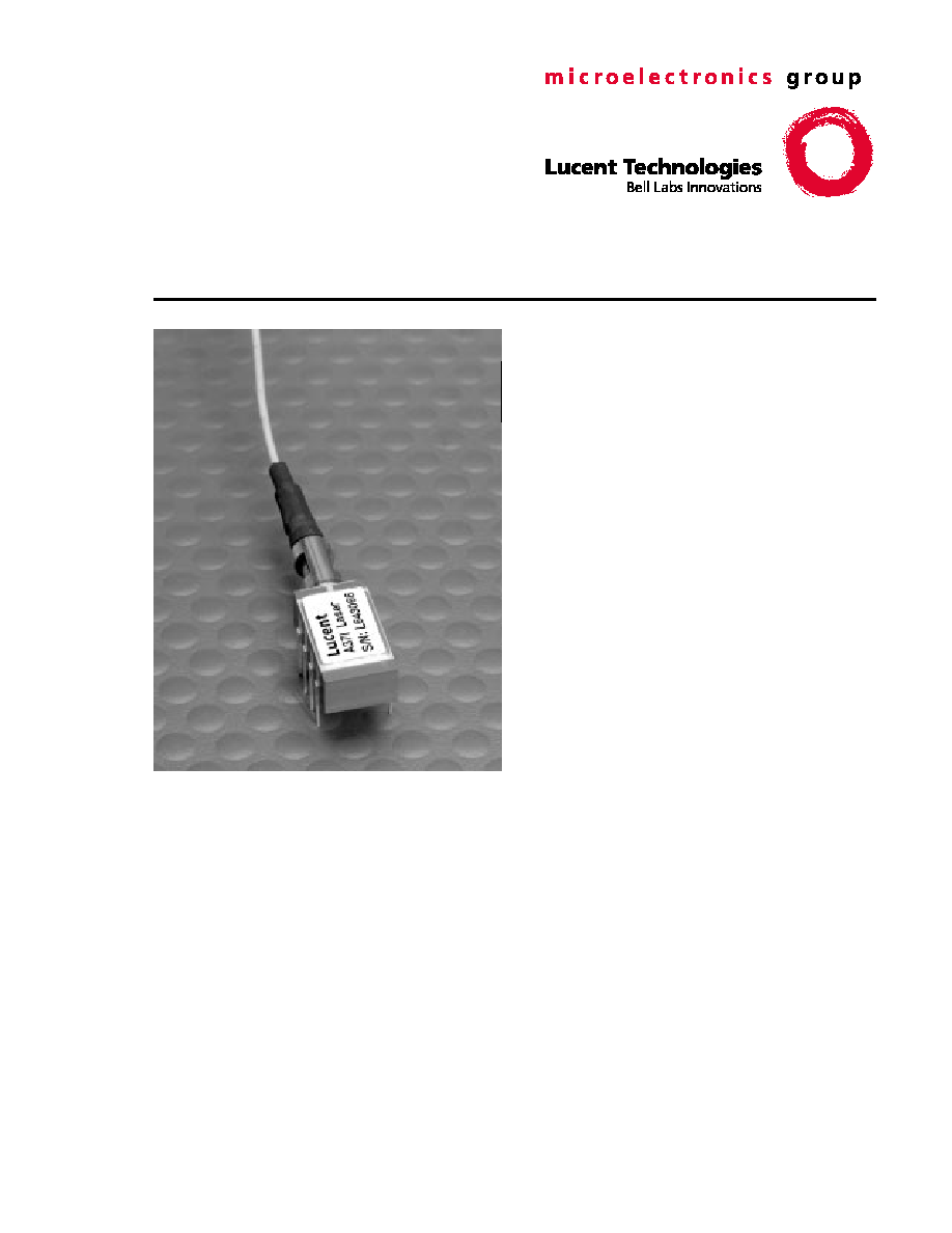
A371-Type Analog Uncooled Isolated
DFB
FastLight
TM
Laser Module
The low-profile A371-Type Analog Laser Module is ideally
suited for CATV applications, particularly in systems where
long spans and superior reliability are the critical consider-
ations.
Features
s
Eight-pin package suitable for CATV applications
s
Narrow linewidth, distributed-feedback,
multiquantum-well (DFB-MQW)1.3
µ
m laser with
single-mode fiber pigtail
s
Wide operating temperature range:
≠40
∞
C to +85
∞
C
s
Frequency range up to 1.0 GHz
s
No thermoelectric cooler required
s
Single- and double-isolated versions available
s
High output power: typically 2.0 mW peak power
coupled into single-mode fiber
s
Hermetically sealed active components
s
Internal back-facet monitor
s
Qualification program: Bellcore TA-983
Applications
s
Video and data applications
s
Downstream telephony and data
s
Return path systems
s
Mixed analog and digital modulation
s
Telecommunications
Benefits
s
Easily board mounted
s
Requires no lead bending
s
No additional heat sinks required
s
Pin compatible with industry-standard, 14-pin laser
module
s
Highly efficient DFB-MQW laser structure allows
for lower threshold and drive currents, and reduced
power consumption
s
High output power allows for longer system spans,
more fiber splits, and greater tolerance of fiber and
connector quality
s
Internal isolator minimizes spurious noise

A371-Type Analog Uncooled Isolated
Data Sheet
DFB
FastLight
Laser Module
January 1999
2
2
Lucent Technologies Inc.
Description
The A371-Type Uncooled Isolated Laser Module con-
sists of a laser diode coupled to a single-mode fiber
pigtail. The device is available in a standard, 8-pin con-
figuration (see Figure 1 and/or Table 1) and is ideal for
CATV applications.
The module includes a narrow linewidth (<1 nm), DFB-
MQW, single-mode laser and an InGaAs PIN photo-
diode back-facet monitor in a hermetically sealed pack-
age.
The device characteristics listed in this document are
met at 2.0 mW output power. Higher- or lower-power
operation is possible. Under conditions of a fixed pho-
todiode current, the change in optical output is typically
±
0.5 dB over an operating temperature range of ≠40
∞
C
to +85
∞
C.
This device incorporates the new Laser 2000 manufac-
turing process from the Optoelectronics unit of Lucent
Technologies Microelectronics Group. Laser 2000 is a
low-cost platform that targets high-volume manufactur-
ing and tight product distributions on all optical subas-
semblies. This platform incorporates an advanced
optical design that is produced on Opto's highly auto-
mated production lines. The Laser 2000 platform is
qualified for central office and uncontrolled environ-
ments, and can be used for applications requiring high
performance and low cost.
Figure 1. A371-Type Analog Uncooled Isolated DFB
Laser Module Schematic, Top View
Table 1. Pin Descriptions
Pin Number
Connection
1
NC
2
Case ground
3
NC
4
Photodiode cathode
5
Photodiode anode
6
Laser diode cathode
7
Laser diode anode
8
NC
5
6
8
7
4
3
1
2
1-900 (C)
Absolute Maximum Ratings
Stresses in excess of the absolute maximum ratings can cause permanent damage to the device. These are abso-
lute stress ratings only. Functional operation of the device is not implied at these or any other conditions in excess
of those given in the operations sections of the data sheet. Exposure to absolute maximum ratings for extended
periods can adversely affect device reliability.
* Rating varies with temperature.
Parameter
Symbol
Min
Max
Unit
Maximum Peak Laser Drive Current or
Maximum Fiber Power*
I
OP
P
MAX
--
--
150
10
mA
mW
Peak Reverse Laser Voltage:
Laser
Monitor
V
RL
V
RD
--
--
2
20
V
V
Monitor Forward Current
I
FD
--
2
mA
Operating Case Temperature Range
T
C
≠40
85
∞
C
Storage Case Temperature Range
T
stg
≠40
85
∞
C
Lead Soldering Temperature/Time
--
--
260/10
∞
C/s
Relative Humidity (noncondensing)
RH
--
85
%

Data Sheet
A371-Type Analog Uncooled Isolated
January 1999
DFB
FastLight
Laser Module
3
Lucent Technologies Inc.
Handling Precautions
Caution: This device is susceptible to damage as a result of electrostatic discharge (ESD). Take proper
precautions during both handling and testing. Follow guidelines such as JEDEC Publication No.
108-A (Dec. 1988).
Although protection circuitry is designed into the device, take proper precautions to avoid exposure to ESD.
Electro/Optical Characteristics
* See Table 5 for more information.
V
R
= reverse voltage.
Table 2. Electro/Optical Characteristics
(over operating temperature range unless otherwise noted)
Parameter
Symbol
Test Conditions
Min
Typ
Max
Unit
Operating Temperature
Range
T
--
≠40
--
85
∞
C
Optical Output Power*
P
F
CW, nominal
--
2
--
mW
Threshold Current
I
TH
T = 25
∞
C
T = full range
5
2
11
--
15
50
mA
mA
Drive Current Above
Threshold
I
MOD
CW, P
F
= 2.0 mW, T = 25
∞
C
CW, I
MON
= const., T = full range
10
7.5
20
--
30
55
mA
Slope Efficiency
SE
CW, P
F
= 2.0 mW, T = 25
∞
C
67
--
200
µ
W/mA
Center Wavelength
C
P
F
= 2.0 mW, CW
1280
--
1335
nm
Spectral Width (≠20 dB)
P
F
= 2.0 mW
--
--
1
nm
Side-mode Suppression
Ratio
SMSR
CW, P
F
= 2.0 mW
30
40
--
dB
Tracking Error
TE
I
MON
= constant, CW
--
0.5
1.25
dB
Forward Voltage
V
F
CW
--
1.1
1.6
V
Input Impedance
R
--
3
--
8
Monitor Current
I
MON
V
R
= 5 V
100
--
1000
µ
A
Monitor Dark Current
I
D
V
R
= 5 V
--
10
200
nA
Wavelength Temperature
Coefficient
--
--
--
0.09
0.1
nm/
∞
C
A371-Type Analog Uncooled Isolated
Data Sheet
DFB
FastLight
Laser Module
January 1999
4
Lucent Technologies Inc.
Electro/Optical Characteristics
(continued)
Analog Operation
The A371-Type Laser Module has the capability of being used in a wide variety of analog operations. These may
include several channels of pure video signals, or a mix of video signals with digital data channels riding on analog
carriers. It is difficult to prepare a single battery of testing conditions that will satisfy all applications. The following
table contains a set of testing conditions that Lucent believes will give a broad indication of the performance of the
A371 Series Laser Module. Please contact your local Field Application Engineer if different testing conditions and
parametric limits are required.
The distortion characteristics are measured using a two-tone test. The frequencies are 13 MHz and 19 MHz. The
second-order distortion components are measured at f1 + f2 = 32 MHz and f1 ≠ f2 = 6 MHz. All third-order distor-
tion components are measured in the frequency range of 5 MHz--200 MHz, and they meet the required level. All
measurements are made with SC-SPC connectors on the laser module pigtails.
* See Table 5 for more information.
Double-isolated version.
Low-performance option.
ß Single- and double-isolated versions.
Table 3. Analog Characteristics
Parameter
Symbol
Test Conditions
Min
Typ
Max
Unit
Output Power*
P
O
CW, T = ≠40
∞
C to +85
∞
C
--
2.0
--
mW
Relative Intensity Noise
RIN
CW, P
F
= 2.0 mW,
Freq. = 5 MHz to 300 MHz;
no fiber loss, T = ≠40
∞
C to +85
∞
C
--
≠155
≠145
dB/Hz
Modulation Bandwidth
BW
≠3 dB, P
F
= 2.0 mW,
T = ≠40
∞
C to +85
∞
C
1.0
--
--
GHz
Second-order Distortions
--
T = 25
∞
C, P
F
= 2.0 mW, OMI = 0.2;
Two-tone test: f1 = 13 MHz,
f2 = 19 MHz; 20 km of fiber,
(7 dB loss) plus connector loss,
f1
±
f2
--
≠54
≠58
≠46
≠50
≠54
≠42
dBc
dBc
dBc
Third-order Distortions
--
T = 25
∞
C, P
F
= 2.0 mW, OMI = 0.2;
Two-tone test: f1 = 13 MHz,
f2 = 19 MHz; 20 km of fiber
(7 dB loss), plus connector loss,
all peaks from 5 MHz--50 MHz
meet this level
--
≠70
≠75
≠69
≠63
≠68
≠61
dBc
dBc
dBc
Spurious Noise
N
SP
T = 25
∞
C, P
F
= 2.0 mW, OMI = 0.2;
ref. to one-tone: 5 MHz to 50 MHz,
20 km of fiber, (7 dB loss) plus
connector loss
--
≠63
≠61
≠60
ß
≠58
dBc
dBc
Spurious Noise (carrier off)
N'
SP
T = 25
∞
C, P
F
= 2.0 mW
--
≠50
≠54
≠45
≠45
≠50
≠40
dBc
dBc
dBc
RF Bandpass Flatness
B
P
F
Peak to valley, 5 MHz to 200 MHz
--
--
1.0
dB

Data Sheet
A371-Type Analog Uncooled Isolated
January 1999
DFB
FastLight Laser Module
5
Lucent Technologies Inc.
Outline Diagram
Dimensions are in inches (and millimeters).
0.010
(0.254)
0.30
(7.62)
0.29
(7.37)
0.085
(2.16)
0.17
(4.32)
0.20 (5.00)
0.165 (4.20)
0.016 (0.410)
0.100 (2.54)
0.300
(7.62)
0.110 (2.79)
0.045 (1.143)
4
3
2
1
5
6
7
8
39.37 (1000) MIN
PIGTAIL LENGTH
0.52 (13.2)
1.06 (27.0)
MIN
TRADEMARK, CODE, LASER SERIAL NUMBER,
AND/OR DATE CODE IN APPROXIMATE AREA SHOWN
1-899.f

A371-Type Analog Uncooled Isolated
Data Sheet
DFB
FastLight Laser Module
January 1999
6
Lucent Technologies Inc.
Qualification Information
The A371-Type Laser Module has completed and passed the following qualification tests and meets the intent of
Bellcore TR-NWT-000468 for interoffice environments and TA-TSY-000983 for outside plant environments.
Table 4. A371-Type Laser Module Qualification Test Plan
Qualification Test
Conditions
Sample Size
Reference
Mechanical Shock
500 G
11
MIL-STD-883
Method 2002
Vibration
20 g, 20 Hz--2,000 Hz
11
MIL-STD-883
Method 2007
Solderability
--
11
MIL-STD-883
Method 2007
Thermal Shock
Delta T = 100
∞
C
11
MIL-STD-883
Method 2003
Fiber Pull
1 kg; 3 times
11
Bellcore 983
Accelerated (Biased) Aging
85
∞
C, 5,000 hrs.
25
Bellcore 983
Section 5.18
High-temperature Storage
85
∞
C, 2,000 hrs.
11
Bellcore 983
Temperature Cycling
500 cycles
11
Bellcore 983
Section 5.20
Cyclic Moisture Resistance
10 cycles
11
Bellcore 983
Section 5.23
Damp Heat
40
∞
C, 95% RH,
1,344 hrs.
11
MIL-STD-202
Method 103
Internal Moisture
<5,000 ppm water vapor
11
MIL-STD-883
Method 1018
Flammability
--
--
TR357
Sec. 4.4.2.5
ESD Threshold
--
6
Bellcore 983
Section 5.22
Data Sheet
A371-Type Analog Uncooled Isolated
January 1999
DFB
FastLight Laser Module
7
Lucent Technologies Inc.
Laser Safety Information
Class IIIb Laser Product
This product complies with 21 CFR 1040.10 and 1040.11.
8.3
µ
m single-mode pigtail or connector
Wavelength = 1.3
µ
m
Maximum power = 10 mW
Because of size constraints, laser safety labeling is not affixed to the module but attached to the outside of the
shipping carton.
Product is not shipped with power supply.
Caution: Use of controls, adjustments, and procedures other than those specified herein may result in
hazardous laser radiation exposure.
DANGER
INVISIBLE RADIATION IS EMITTED FROM THE END OF THE FIBER OR CONNECTOR.
AVOID DIRECT EXPOSURE TO THE BEAM.
DO NOT VIEW WITH OPTICAL INSTRUMENTS.
DANGER
INVISIBLE LASER RADIATION
AVOID DIRECT EXPOSURE TO BEAM.
Indium Gallium Arsenide Phosphide Laser
10 mW max. Output @ 1.3 µm
Class IIIb Laser Product
Complies with 21 CFR 1040.10 and 1040.11
µ
m
A371-Type Analog Uncooled Isolated Data Sheet
DFB
FastLight Laser Module
January 1999
For additional information, contact your Microelectronics Group Account Manager or the following:
INTERNET: http://www.lucent.com/micro, or for Optoelectronics information, http://www.lucent.com/micro/opto
E-MAIL: docmaster@micro.lucent.com
N. AMERICA: Microelectronics Group, Lucent Technologies Inc., 555 Union Boulevard, Room 30L-15P-BA, Allentown, PA 18103
1-800-372-2447, FAX 610-712-4106 (In CANADA: 1-800-553-2448, FAX 610-712-4106)
ASIA PACIFIC: Microelectronics Group, Lucent Technologies Singapore Pte. Ltd., 77 Science Park Drive, #03-18 Cintech III, Singapore 118256
Tel. (65) 778 8833, FAX (65) 777 7495
CHINA: Microelectronics Group, Lucent Technologies (China) Co., Ltd., A-F2, 23/F, Zao Fong Universe Building, 1800 Zhong Shan Xi Road,
Shanghai 200233 P. R. China
Tel. (86) 21 6440 0468, ext. 316, FAX (86) 21 6440 0652
JAPAN: Microelectronics Group, Lucent Technologies Japan Ltd., 7-18, Higashi-Gotanda 2-chome, Shinagawa-ku, Tokyo 141, Japan
Tel. (81) 3 5421 1600, FAX (81) 3 5421 1700
EUROPE: Data Requests: MICROELECTRONICS GROUP DATALINE: Tel. (44) 1189 324 299, FAX (44) 1189 328 148
Technical Inquiries: OPTOELECTRONICS MARKETING: (44) 1344 865 900 (Ascot UK)
Lucent Technologies Inc. reserves the right to make changes to the product(s) or information contained herein without notice. No liability is assumed as a result of their use or application. No
rights under any patent accompany the sale of any such product(s) or information.
FastLight is a trademark of Lucent Technologies Inc.
Copyright © 1999 Lucent Technologies Inc.
All Rights Reserved
January 1999
DS99-035LWP (Replaces DS98-433LWP)
Ordering Information
Table 5. Ordering Information
Device Code Comcode Pfiber Connector
Performance
Option
A371-20AS 108053307 2.0 mW SC-PC Single Isolator
A371-20BS 108173956 2.0 mW SC-APC Single Isolator
A371-20FS 108120445 2.0 mW FC-PC Single Isolator
A371-20GS 108130444 2.0 mW FC-APC Single Isolator
A371-20NS 108043522 2.0 mW none Single Isolator
A371-22AD 108348699 2.0 mW SC-PC Double Isolator
A371-22BD 108348707 2.0 mW SC-APC Double Isolator
A371-22FD 108348715 2.0 mW FC-PC Double Isolator
A371-22GD 108348723 2.0 mW FC-APC Double Isolator
A371-22ND 108348731 2.0 mW none Double Isolator
A371-24AS 108401019 2.0 mW SC-PC Low Performance
A371-24BS 108401027 2.0 mW SC-APC Low Performance
A371-24FS 108401035 2.0 mW FC-PC Low Performance
A371-24GS 108401043 2.0 mW FC-APC Low Performance
A371-24NS 108401050 2.0 mW none Low Performance