
CW20P-Type
CW Tunable, Wavelength-Stabilized Laser Module
Advance Data Sheet, Rev. 1
June 2001
Offering multiple channel selections and SONET/SDH compat-
ibility, the CW20P-Type CW DBR Laser Module is manufac-
tured in a 24-pin metallic DIP with a polarization-maintaining
fiber (PMF) pigtail.
Features
s
Tunable up to twenty ITU-T 50 GHz channels
s
For use with lithium niobate modulators
s
Integrated Etalon stabilizer
--Replaces external wavelength lockers
s
1528.77 nm to 1610.0 nm wavelengths
s
Compact design
s
Remote programmability
s
Asynchronous serial interface for module communi-
cation
s
High output power, up to 20 mW
s
Low profile, 24-pin package
s
Laser bias monitor alarm
s
Module enable/disable input
Applications
s
SONET/SDH extended-reach
s
Long-haul, very dense, wave-division multiplexing
(DWDM)
s
High-speed data communication
s
Flexible wavelength systems
Description
The CW20P-type laser modules are designed for use
in transmission systems and high-speed data com-
munication applications. The device supports
20 wavelengths. The module uses an RS-232 inter-
face to adjust various module functions such as
wavelength. In addition, the interface provides acces-
sibility to the alarm and monitor outputs.
The modules meet all present
Telcordia Technolo-
gies
* GR-253-CORE requirements and the ITU-T
G.957 and G.958 recommendations. The modules
are also suited for extended distance data and net-
working applications when used in conjunction with a
lithium niobate modulator.
The CW20P uses a 1.5
�
m distributed Bragg reflec-
tor (DBR) laser with an integrated wavelength stabi-
lizer. By integrating the wavelength stabilizer with the
DBR laser chip, the device offers a compact, cost-
effective solution for low-dispersion transmission.
Devices are provided at wavelengths that are com-
patible with the ITU-T wavelength standards at
200 GHz, 100 GHz, and 50 GHz. The package also
contains a thermoelectric cooler, thermistor, back-
facet monitor, and optical isolator. The laser module
requires 5 V, �5.2 V, and 3.3 V.
*
Telcordia Technologies
is a trademark of Telcordia Technologies,
Inc.
CW20P-Type
Advance Data Sheet, Rev. 1
CW Tunable, Wavelength-Stabilized Laser Module
June 2001
2
2
Agere Systems Inc.
Module Processing
The module can withstand normal wave soldering pro-
cesses. The complete transmitter module is not her-
metically sealed; therefore, it should not be immersed
in or sprayed with any cleaning solution or solvents.
The process cap and fiber pigtail jacket can deform at
temperatures greater than 85 �C. The transmitter pins
can be wave-soldered at a maximum temperature of
250 �C for 10 seconds.
Connector Options
The standard fiber-optic pigtail is an 8
�
m core PMF
panda-type fiber. (914
�
m) diameter, tight-buffered
outer jacket. The standard length is 39 in. � 4 in.
(1 m � 10 cm) and is terminated with an
ST
�
optical
connector.
Installation Considerations
Although the module has been designed with rugged-
ness in mind, care should be used during handling.
The optical connector should be kept free from dust,
and the process cap should be kept in place as a dust
cover when the device is not connected to a cable. If
contamination is present on the optical connector, the
use of canned air with an extension tube should
remove any debris. Other cleaning procedures are
identified in the
Cleaning Fiber-Optic Assemblies
Tech-
nical Note (TN95-010LWP).
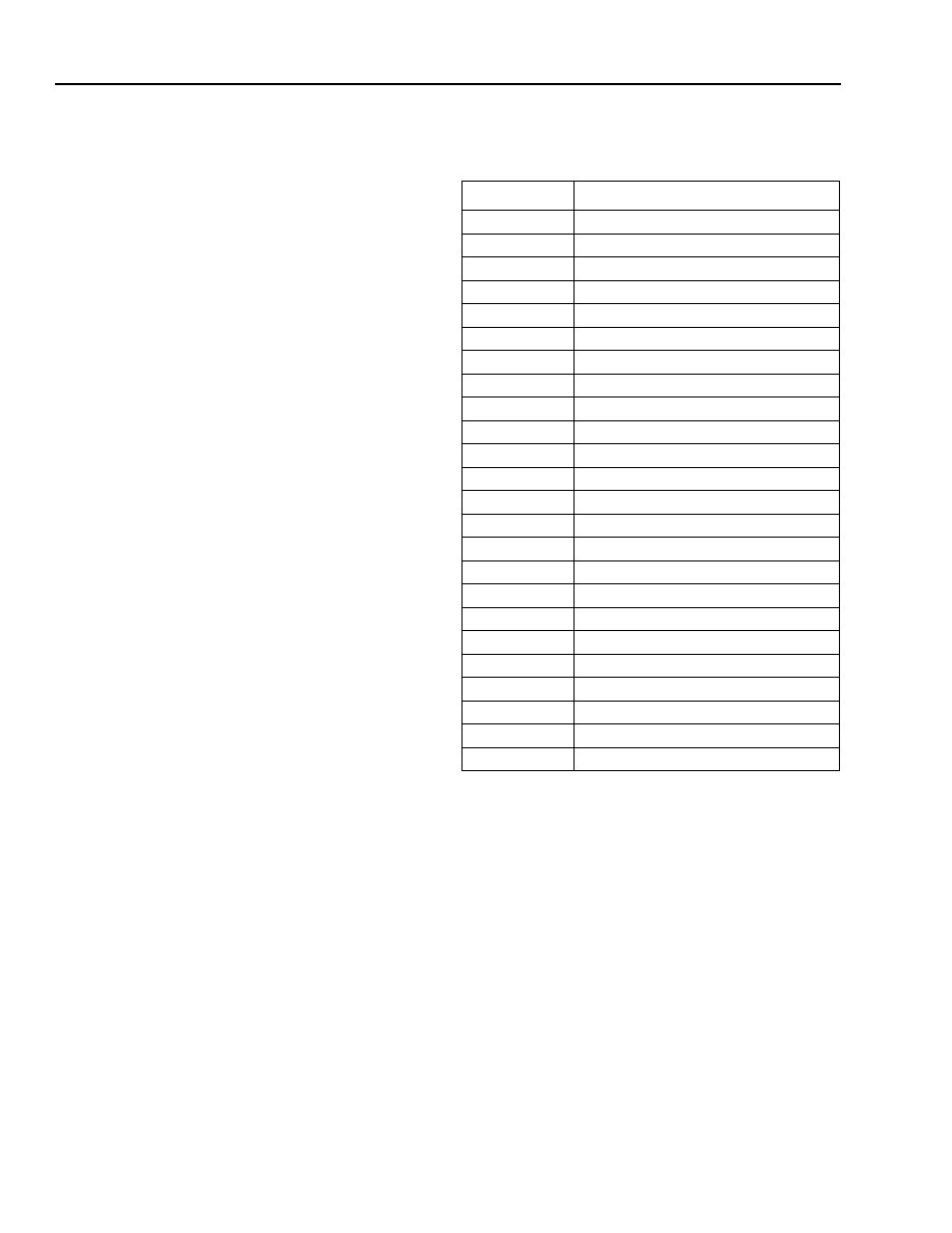
Pin Information
1. Laser back-facet and bias alarm functions are customer-use
options that are not required for normal operations of the transmit-
ter
and are normally used during manufacture and for diagnostics.
The output will optionally be either a logic signal or an analog volt-
age. All alarm, select, and enable signals are active-high.
2. NUC = no user connection.
Table 1. Pin Descriptions
Pin Number
Name
1
Ground (TEC)
2
Back-facet Monitor
1
3
Bias Monitor/Laser Degrade Alarm
1
4
CW Enable
5
NUC
2
6
Ground
7
Wavelength-Deviation Error Alarm
8
RS-232 Interface (Tx)
9
RS-232 Interface (Rx)
10
Dither Input
11
Ground
12
V
EE
13
V
CC
14
V
TEC
(TEC supply voltage)
15
Ground
16
NUC
2
17
Ground
18
NUC
2
19
Ground
20
NUC
2
21
Ground
22
NUC
2
23
Ground
24
V
CC

Advance Data Sheet, Rev. 1
CW20P-Type
June 2001
CW Tunable, Wavelength-Stabilized Laser Module
3
Agere Systems Inc.
Absolute Maximum Ratings
Stresses in excess of the absolute maximum ratings can cause permanent damage to the device. These are abso-
lute stress ratings only. Functional operation of the device is not implied at these or any other conditions in excess
of those given in the operations sections of the data sheet. Exposure to absolute maximum ratings for extended
periods can adversely affect device reliability.
Characteristics
(Minimum and maximum values specified over operating case temperature range at 50% duty cycle data signal.
Typical values are measured at room temperature unless otherwise noted.)
Parameter
Symbol
Min
Max
Unit
Supply Voltage (positive)
V
CC
--
5.5
V
Supply Voltage (negative)
V
EE
--
�6.0
V
Operating Case Temperature Range
T
C
0
70
�C
Storage Case Temperature Range
T
stg
�40
85
�C
Lead Soldering Temperature/Time
--
--
250/10
�C/s
Relative Humidity (noncondensing)
RH
--
85
%
Minimum Fiber-Bend Radius
--
1.5 (38.1)
--
in. (mm)
Table 2. Electrical Characteristics
Parameter
Symbol
Min
Typ
Max
Unit
dc Power Supply Voltage
V
CC
4.75
5.0
5.25
V
dc Power Supply Current
I
CC
--
350
500
mA
dc Negative Supply Voltage
V
EE
�5.46
�5.2
�4.94
V
dc Negative Supply Current
I
EE
--
--
250
mA
Power Dissipation
P
DISS
--
10
--
W
Module Disable Voltage (TTL) V
IH
V
DIS
4.2
--
--
V
Module Enable Voltage (TTL) V
IL
V
EN
0.0
--
0.8
V
Deviation Alarm:
Levels (CMOS) V
OL
Levels (CMOS) V
OH
Setting
V
ALARM N
V
ALARM
ALARM
0
4.05
�20
--
--
--
0.6
--
20
V
V
pm
Laser Degrade Alarm:
Levels (CMOS) V
OH
Levels (CMOS) V
OL
Setting
V
ALARM
V
ALARM N
LD
ALARM
4.05
0
--
--
--
--
--
0.6
I
BOL
x 125%
V
V
mA
TEC Current
I
TEC
--
1
2
A
TEC Voltage
V
TEC
3.2
3.3
3.5
V
CW20P-Type
Advance Data Sheet, Rev. 1
CW Tunable, Wavelength-Stabilized Laser Module
June 2001
4
Agere Systems Inc.
Characteristics
(continued)
1. Output power definitions and measurement per ITU-T Recommendation G.957.
2.
Ratio of the average output power in the dominant longitudinal mode to the power in the most significant side mode under fully
modulated conditions.
Qualification and Reliability
To help ensure high product reliability and customer satisfaction, Agere Systems is committed to an intensive qual-
ity program that starts in the design phase and proceeds through the manufacturing process. Optoelectronics mod-
ules are qualified to Agere Systems internal standards using MIL-STD-883 test methods and procedures and using
sampling techniques consistent with
Telcordia Technologies
requirements. This qualification program fully meets
the intent of
Telcordia
reliability practices TR-NWT-000468 and TA-TSY-000983. In addition, the Agere Systems
design, development, and manufacturing facility has been certified to be in full compliance with the latest
ISO
*
9001 Quality System Standards.
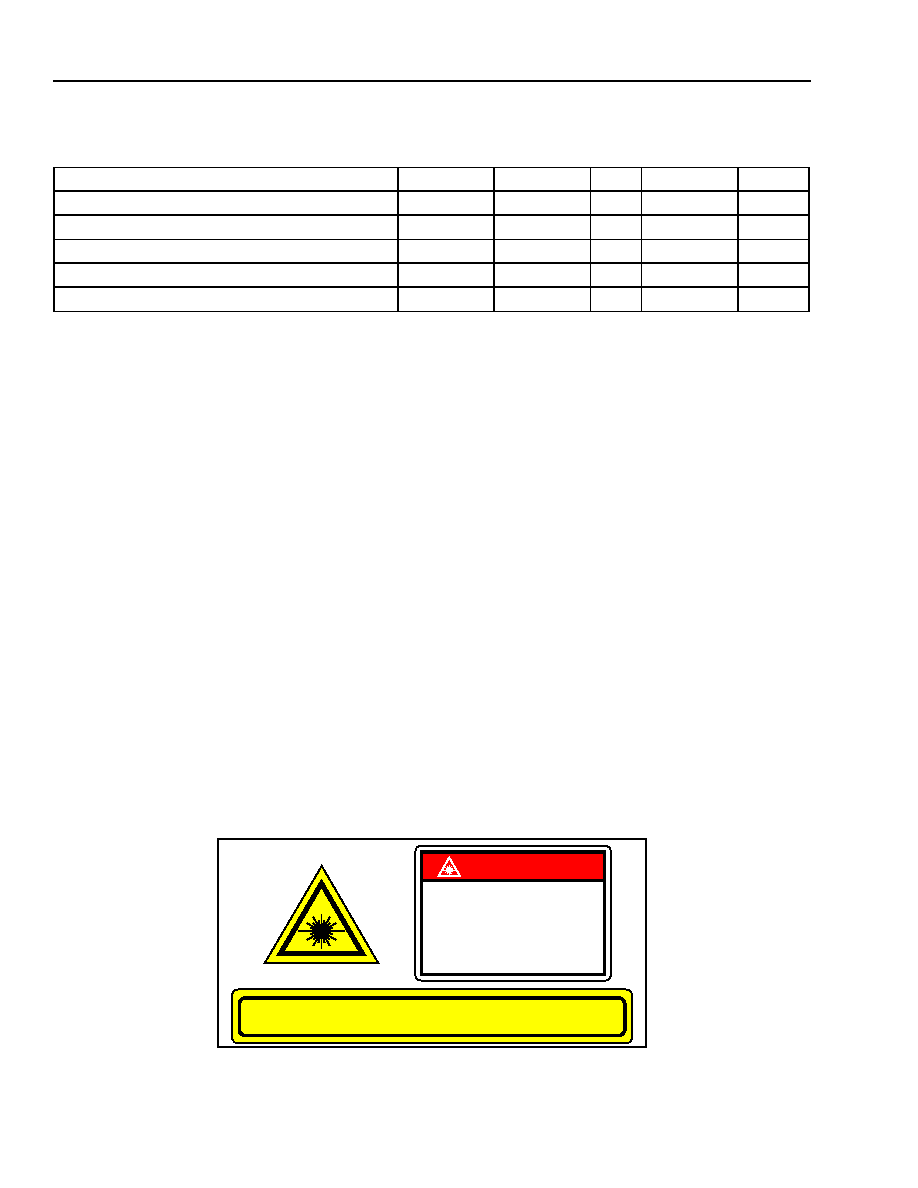
Laser Safety Information
Class IIIb Laser Product
All versions of the CW20P-type modules are classified as Class IIIb laser products per FDA/CDRH, 21 CFR 1040
Laser Safety requirements. The device will be classified with the FDA under an accession number to be deter-
mined.
This product complies with 21 CFR 1040.10 and 1040.11.
8
�
m/125
�
m diameter single-mode fiber pigtail with 914
�
m tight-buffered jacket and connector.
Product is not shipped with power supply.
Caution: Use of controls, adjustments, and procedures other than those specified herein may result in
hazardous laser radiation exposure.
*
ISO
is a registered trademark of The International Organization for Standardization.
Table 3. Optical Characteristics
Parameter
Symbol
Min
Typ
Max
Unit
Average Optical-Fiber Power Output (BOL)
1
P
F
13.0
--
--
dBm
Output Power Variation (BOL)
P
�0.5
--
0.5
dB
Frequency Drift
C
�2.5
--
2.5 GHz
Center Wavelength Range (See Table 6.)
C
1528.77
--
1610.53
nm
Side-mode Suppression Ratio
2
SMSR
32
--
--
dB
DANGER
INVISIBLE LASER RADIATION
IS EMITTED FROM THE END
OF FIBER OR CONNECTOR
Avoid direct exposure to beam
Do not view beam directly with
optical instruments
INVISIBLE LASER RADIATION EMITTED FROM END OF FIBER OR CONNECTOR
Avoid exposure to beam
Class IIIb Laser Product FDA/CDRH, 21 CFR 1040
Max. Output: 40 mW
Wavelength: 1.5
�
m

Advance Data Sheet, Rev. 1
CW20P-Type
June 2001
CW Tunable, Wavelength-Stabilized Laser Module
5
Agere Systems Inc.
Outline Drawings
Dimensions are in inches and (millimeters).
2.008
(51.00)
2.89
(73.4)
1.100
(27.94)
1.075
(27.31)
0.100
(2.54)
0.085
(2.16)
0.50
(12.70)
1.025
(26.04)
1.5
(38.1)
PIN 24
0.236
(5.99)
0.236
(5.99)
4 x
0.106 (2.69) THRU
39.37
(1000)
0.012
(0.3)
STANDOFF
HEIGHT
0.018
(0.46)
DIA
PIN 13
PIN 1
PIN 12
0.39
(10.00)
MAX
0.28
(7.00)
MAX
STANDOFF
(TYP. 4 PLCS)
(TOP VIEW)
(SIDE VIEW)
(BOTTOM VIEW)
3.50
(8.89)
1-1263 (F)