 | –≠–ª–µ–∫—Ç—Ä–æ–Ω–Ω—ã–π –∫–æ–º–ø–æ–Ω–µ–Ω—Ç: D171-TYPE | –°–∫–∞—á–∞—Ç—å:  PDF PDF  ZIP ZIP |
Document Outline
- Features
- Applications
- Benefits
- Description
- Absolute Maximum Ratings
- Handling Precautions
- Electrical Characteristics
- Optical Characteristics
- Outline Diagram
- Qualification Information
- Ordering Information
- List of Figures
- Figure 1. Typical Bias Connection
- Figure 2. Equivalent ac Circuit for Digital Applications
- Figure 3. D171-Type PIN Photodetector Schematic
- List of Tables
- Table 1. Pin Descriptions
- Table 2. D171-Type PIN Photodetector Qualification Test Plan
- Contact Us
Advance Data Sheet
March 1999
D171-Type
FastLight
TM
PIN Photodetectors
The D171-Type PIN Photodetectors feature a rear-illuminated
planar diode structure with a low-capacitance 4-mil active
area for maximum responsivity and speed.
Features
s
Low-profil e, 4-lead mini-DIL pa ckage
-- Suita ble for SONET applications
s
High per formance
-- High speed (<0.5 ns typical rise and fall time)
-- High responsivity (0.85 A/W typical)
-- Low da rk current
s
Planar st ructure for high reliability
s
Wavelength : 1.1
µ
m--1.6
µ
m
s
50
µ
m core multimode fiber
s
Wide operating temperature range
:
≠40
∞
C to +85
∞
C
s
Wide bandwidth
s
Qualification program : Bellcor e TA-NWT-983
Applications
s
Long-reach SONET OC-3/OC-12 systems and
SDH STM-1/STM-4 systems
s
Secure digital data systems
Benefits
s
Compact si ze
s
Easily board mounted
Advance Data Sheet
D171-Type
FastLight
PIN Photodetectors
March 1999
2
2
Lucent Technologies Inc.
Description
The D171-Type Photodetector consists of a PIN cou-
pled to a multimode fiber pigail. The device is available
in a 4-pin mini-DIL configuration (see Figure 3 and/or
Table 1) and is ideal for long-reach (SONET) and other
high-speed digital applications.
The D171-Type PIN Photodetector is a rear-illuminated
planar diode structure with a low-capacitance active
area for maximum responsivity and speed.
This device incorporates the new Laser 2000 manufac-
turing process from the Optoelectronics Products unit
of Lucent Technologies Microelectronics Group. Laser
2000 is a low-cost platform that targets high-volume
manufacturing and tight product distributions on all
optical subassemblies. This platform incorporates an
advanced optical design that is produced on Opto's
highly automated production lines. The Laser 2000
platform is qualified for central office and uncontrolled
environments, and can be used for applications requir-
ing high perfomance and low cost.
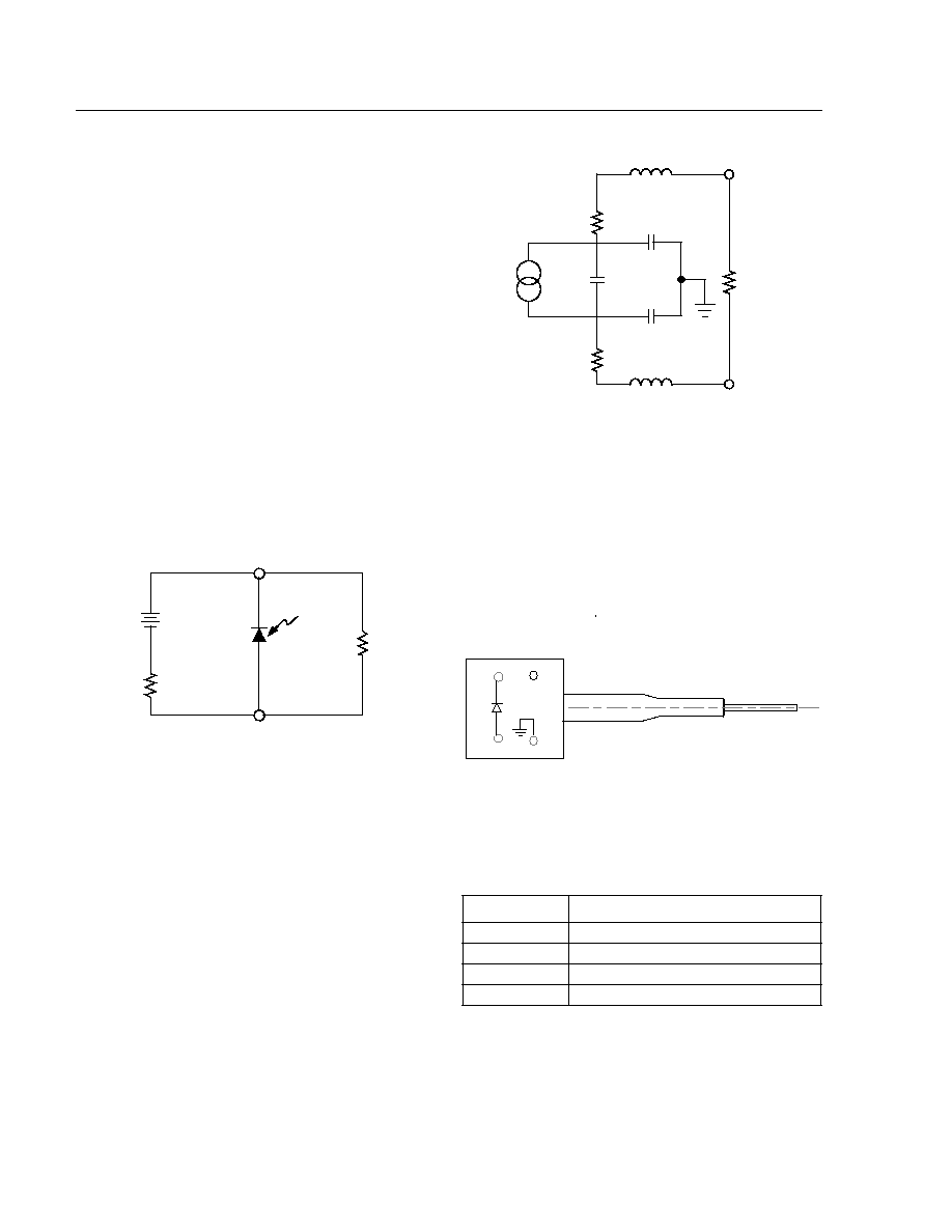
Figure 1. Typical Bias Connection
Notes:
This equivalent circuit is intended for modeling the package
capacitance. Minimum capacitance is achieved by connecting the N-
side to ground, applying a negative voltage to the P-side, and allowing
the package to float (i.e., not connected to ground).
Typical values are as follows:
C
O
= 0.3 pF to 0.5 pF.
L
N
, L
P
= 3.0 nH.
R
N
, R
P
= 5
.
C
N
= 0.4 pF.
C
P
= 0.1 pF.
Figure 2. Equivalent ac Circuit for Digital
Applications
Figure 3. D171-Type PIN Photodetector Schematic
(Top View)
10 V
R
BIAS
LOAD
PIN 2
PIN 3
N
P
Table 1. Pin Descriptions
Pin Number
Description
1
NC
2
Photodiode Cathode
3
Photodiode Anode
4
Case Ground
1-697
R
N
LOAD
PIN 3
PIN 2
R
P
L
P
L
N
C
O
C
N
C
P
N
P
LOAD
4
3
1
2
1-902.a

Advance Data Sheet
March 1999
D171-Type
FastLight
PIN Photodetectors
3
Lucent Technologies Inc.
Absolute Maximum Ratings
Stresses in excess of the absolute maximum ratings can cause permanent damage to the device. These are abso-
lute stress ratings only. Functional operation of the device is not implied at these or any other conditions in excess
of those given in the operational sections of the data sheet. Exposure to absolute maximum ratings for extended
periods can adversely affect device reliability.
* The recommended reverse bias voltage is 5 V to 15 V.
Handling Precautions
Electrostatic Discharge
CAUTION: This device is susceptible to damage as a result of electrostatic discharge. Take proper
precautions during both handling and testing. Follow guidelines such as JEDEC Publication
No. 108-A (Dec. 1988).
Although protection circuitry is designed into the device, take proper precautions to avoid exposure to ESD.
Electrical Characteristics
T
C
= 25
∞
C. Determined with a 50
load.
* The minimum capacitance configuration occurs when the N-side of the PIN is grounded and a negative voltage is applied to the P-side, with
the package floating, not grounded (value reference only; not tested in manufacture).
Optical Characteristics
T
C
= 25
∞
C.
Parameter
Symbol
Min
Max
Unit
Operating Temperature Range
T
A
≠40
85
∞
C
Storage Temperature Range
T
stg
≠40
90
∞
C
Forward Voltage
V
F
--
0
V
Reverse Voltage*
V
R
--
30
V
Photocurrent
--
--
4
mA
Humidity
--
--
95
%
Parameter
Symbol
Min
Typ
Max
Unit
Capacitance (f < 900 MHz)*
--
--
0.65
0.70
pF
Rise/Fall Time
t
R
/t
F
--
<0.5
--
ns
Dark Current
I
D
--
1
5
nA
Reverse Voltage
V
R
2
5
30
V
Parameter
Symbol
Min
Typ
Max
Unit
Responsivity
R
0.75
0.85
--
A/W
Wavelength Range
--
1.1
--
1.6
µ
m
Advance Data Sheet
D171-Type
FastLight
PIN Photodetectors
March 1999
4
Lucent Technologies Inc.
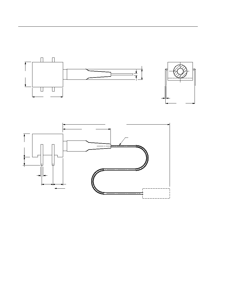
Outline Diagram
Dimensions are in inches and (millimeters)
.
0.195
(4.95)
45.28
±
1.57
(1150
±
40)
FIBER
OPTICAL
CONNECTOR
1.25 MAX
(31.75)
A
0.100
(2.54)
0.016
(0.41)
0.100
(2.54)
0.114
(2.90)
2
1
3
4
0.310
(7.87)
0.250
(6.35)
ÿ 0.04
(1.02)
ÿ 0.180
(4.57)
+
0.012
TYP
(0.30)
0.300
(7.62)
SECTION A-A
1-933

Advance Data Sheet
March 1999
D171-Type
FastLight
PIN Photodetectors
5
Lucent Technologies Inc.
Qualification Information
The D171-Type PIN Photodetector has completed the following qualification tests and meets the intent of Bellcore
TR-NWT-000468 for interoffice environments and TA-NWT-000983 for outside plant environments.
Table 2. D171-Type PIN Photodetector Qualification Test Plan
Test
Conditions
Sample Size
Reference
Mechanical Shock
500 G
11
MIL-STD-883
Method 2002
Vibration
20 g, 20 Hz--2000 Hz
11
MIL-STD-883
Method 2007
Solderability
--
11
MIL-STD-883
Method 2007
Thermal Shock
Delta T = 100
∞
C
11
MIL-STD-883
Method 2003
Fiber Pull
1 kg; 3 times
11
Bellcore 983
Accelerated (biased) Aging
85
∞
C, 5000 hrs.
25
Bellcore 983
Section 5.18
High-temperature Storage
85
∞
C, 2000 hrs.
11
Bellcore 983
Temperature Cycling
500 cycles
11
Bellcore 983
Section 5.20
Cyclic Moisture Resistance
10 cycles
11
Bellcore 983
Section 5.23
Damp Heat
40
∞
C, 95% RH, 1344 hrs.
11
MIL-STD-202
Method 103
Internal Moisture
<5000 ppm water vapor
11
MIL-STD-883
Method 1018
Flammability
--
--
TR357
Sec. 4.4.2.5
ESD Threshold
--
6
Bellcore 983
Section 5.22