 | –≠–ª–µ–∫—Ç—Ä–æ–Ω–Ω—ã–π –∫–æ–º–ø–æ–Ω–µ–Ω—Ç: D2300 | –°–∫–∞—á–∞—Ç—å:  PDF PDF  ZIP ZIP |
Document Outline
- Features
- Applications
- Description
- Controlled Feedback
- Controlled Temperature
- Controlled Power
- Standard Package
- Pin Information
- Absolute Maximum Ratings
- Handling Precautions
- Power Sequencing
- Electrostatic Discharge
- Mounting Instructions
- Characteristics
- Outline Diagram
- Class IIIb Laser Product
- Ordering Information
- List of Tables
- Table 1. Electrical Characteristics
- Table 2. Optical Characteristics
- Table 3. Ordering Information
- List of Figures
- Figure 1. Circuit Schematic
- Figure 2. Fillister Head Screw
- Contact Us

Data Sheet
February 2000
1.3
µ
m D2300-Type Laser
Isolated DFB Laser Module
The 1.3
µ
m D2300-Type Laser Module is offered in a 14-pin,
hermetic, butterfly package.
Features
s
Integrated optical isolator
s
SONET/SDH compatible up to OC-48/STM-16
s
High-performance, distributed-feedback (DFB)
laser
s
High optical power available
s
Industry-standard, 14-pin butterfly package
s
Characterized at 2.488 Gbits/s (NRZ)
s
Wide operating case temperature range:
≠40
∞
C to +80
∞
C
s
InGaAs, PIN photodetector back-facet monitor
s
Low threshold current
s
High reliability
s
Qualified to meet the intent of
Telcordia Technolo-
gies
* 468
*
Telcordia Technologies
is a trademark of Bell Communications
Research, Inc.
Applications
s
Telecommunications:
-- SONET/SDH
-- Long reach
-- Interexchange
s
Digital video
D2300

2
2
Lucent Technologies Inc.
Data Sheet
February 2000
Isolated DFB Laser Module
1.3
µ
m D2300-Type Digital
Description
The D2300-Type Digital Isolated DFB Laser Module
contains an internally cooled, InGaAsP, distributed-
feedback (DFB) laser designed for 1.3
µ
m applications.
The laser is designed to be used in OC-12/STM-4 (622
Mbits/s) and OC-48/STM-16 (2.488 Gbits/s) for long-
reach and extended-reach applications.
The device is available with an average output power of
0 dBm (3 dBm peak), which meets the SONET/SDH
standard.
Controlled Feedback
The module contains an internal optical isolator that
suppresses optical feedback in laser-based, fiber-optic
systems. Light reflected back to the laser is attenuated
a minimum of 30
dB.
Controlled Temperature
An integral thermoelectric cooler (TEC) provides stable
thermal characteristics. The TEC allows for heating and
cooling of the laser chip to maintain a temperature of
25
∞
C for case temperatures from ≠40
∞
C to +80
∞
C.
The laser temperature is monitored by the internal ther-
mistor, which can be used with external circuitry to con-
trol the laser chip temperature.
Controlled Power
An internal, InGaAs, PIN photodiode functions as the
back-facet monitor. The photodiode monitors emission
from the rear facet of the laser and, when used in con-
junction with control circuitry, can control optical power
launched into the fiber. Normally, this configuration is
used in a feedback arrangement to maintain the aver-
age laser output power.
Standard Package
The laser module is fabricated in a 14-pin, hermetic,
metal/ceramic butterfly package. The package also
incorporates a bias tee that separates the dc-bias path
from the RF input. The RF input has a nominal 25
impedance. The laser module is equipped with a sin-
gle-mode fiber. The pigtail has an 8
µ
m core and
125
µ
m cladding with a 900
µ
m tight buffer coating.
Lucent Technologies Microelectronics Group optoelec-
tronic components are qualified to rigorous internal
standards that are consistent with
Telcordia Technolo-
gies
TR-NWT-000468. All design and manufacturing
operations are
ISO
* 9001 certified. The module is fully
qualified for central office applications.
*
ISO
is a registered trademark of The International Organization for
Standardization.
Pin Information
* A positive current through the thermoelectric heat pump cools the
laser.
Both leads should be grounded for optimum performance.
Top view.
Figure 1. Circuit Schematic
Pin
Name
1
Thermistor
2
Thermistor
3
Laser dc Bias (cathode) (≠)
4
Back-facet Monitor Anode (≠)
5
Back-facet Monitor Cathode (+)
6
Thermoelectric Cooler (+)*
7
Thermoelectric Cooler (≠)*
8
Case Ground
9
Case Ground
10
Case Ground
11
Laser Anode
(+)
12
RF Laser Input Cathode (≠)
13
Laser Anode
(+)
14
Case Ground
1-567
TEC
L1
160 nH
ISOLATOR
R1
20
PACKAGE
GROUNDS
≠
+
+
≠
≠
+
≠
+
7
6
5
4
3
2
1
8
9
10
11
12
13
TH
10 k
14

Data Sheet
February 2000
Lucent Technologies Inc.
3
Isolated DFB Laser Module
1.3
µ
m D2300-Type Digital
Absolute Maximum Ratings
Stresses in excess of the absolute maximum ratings can cause permanent damage to the device. These are abso-
lute stress ratings only. Functional operation of the device is not implied at these or any other conditions in excess
of those given in the performance characteristics of the data sheet. Exposure to absolute maximum ratings for
extended periods can adversely affect device reliability.
* Does not apply to shipping container.
Parameter
Symbol
Min
Max
Unit
Laser Reverse Voltage
V
RLMAX
--
2
V
dc Forward Current
I
FLMAX
--
150
mA
Operating Case Temperature Range
T
C
≠
40
80
∞
C
Storage Case Temperature Range*
T
stg
≠
40
85
∞
C
Photodiode Reverse Voltage
V
RPDMAX
--
10
V
Photodiode Forward Current
I
FPDMAX
--
1
mA
Handling Precautions
Power Sequencing
To avoid the possibility of damage to the laser module
from power supply switching transients, follow this turn-
on sequence:
1. All ground connections
2. Most negative supply
3. Most positive supply
4. All remaining connections
Reverse the order for the proper turn-off sequence.
Electrostatic Discharge
CAUTION: This device is susceptible to damage as
a result of electrostatic discharge. Take
proper precautions during both handling
and testing. Follow guidelines such as
JEDEC Publication No. 108-A (Dec.
1988).
Lucent employs a human-body model (HBM) for ESD-
susceptibility testing and protection-design evaluation.
ESD voltage thresholds are dependent on the critical
parameters used to define the model. A standard HBM
(resistance = 1.5 k
, capacitance = 100 pF) is widely
used and, therefore, can be used for comparison pur-
poses. The HBM ESD threshold presented here was
obtained using these circuit parameters:
Mounting Instructions
The minimum fiber bend radius is 1.18 in. (30 mm).
To avoid degradation in performance, mount the mod-
ule on the board as follows:
1. Place the bottom flange of the module on a flat heat
sink at least 0.5 in. x 1.180 in. (12.7 mm x 30 mm) in
size. The surface finish of the heat sink should be
better than 32
µ
in. (0.8
µ
m), and the surface flatness
must be better than 0.001 in. (25.4
µ
m). Using ther-
mal conductive grease is optional; however, thermal
performance can be improved by up to 5% if conduc-
tive grease is applied between the bottom flange and
the heat sink.
2. Mount four #2-56 screws with Fillister heads
(M2-3 mm) at the four screw-hole locations (see Out-
line Diagram). The Fillister head diameter must not
exceed 0.140 in. (3.55 mm). Do not apply more than
1 in.-lb. of torque to the screws.
Note: Dimensions are in inches and (millimeters).
Figure 2. Fillister Head Screw
Parameter
Value
Unit
Human-body Model
>400
V
1-532
0.118
(3.00)
0.062 (1.58)
0.140
(3.56)
0.031 (0.79)
0.129 (3.28) R
0.086
(2.18)
0.041 (1.04)

4
Lucent Technologies Inc.
Data Sheet
February 2000
Isolated DFB Laser Module
1.3
µ
m D2300-Type Digital
Characteristics
Minimum and maximum values are testing requirements. Typical values are characteristics of the device and are
the result of engineering evaluations. Typical values are for information purposes only and are not part of the test-
ing requirements.
* Standard operating condition is 5.0 V reverse bias.
Ratio of thermistor resistance at 0
∞
C to thermistor resistance at 50
∞
C.
Table 1. Electrical Characteristics (at 25
∞
C Laser Temperature)
Parameter
Symbol
Test Conditions
Min
Typ
Max
Unit
Laser Forward Voltage
V
LF
L
F
= 2 mW (CW)
--
1.3
1.8
V
Slope Efficiency
L
F
= 2 mW (CW)
0.025
0.06
--
mW/mA
Threshold Current
I
TH
--
--
15
50
mA
Monitor Reverse-bias Voltage*
V
RMON
--
3
5
10
V
Monitor Current
I
RMON
P
O
= 1 mW (CW)
0.1
1.0
2.0
mA
Monitor Dark Current
I
D
I
F
= 0, V
RMON
= 5 V
--
0.01
0.1
µ
A
Input Impedance
Z
IN
--
--
25
--
Thermistor Current
I
TC
--
10
--
100
µ
A
Resistance Ratio
--
--
8.6
--
9.6
--
Thermistor Resistance
R
TH
T
L
= 25
∞
C
9.5
--
10.5
k
TEC Current
I
TEC
T
L
= 25
∞
C, T
C
= 70
∞
C
--
--
1.0
A
TEC Voltage
V
TEC
T
L
= 25
∞
C, T
C
= 70
∞
C
--
--
2.0
V
TEC Capacity
T
T
C
= 80
∞
C
55
--
--
∞
C
Table 2. Optical Characteristics (at 25
∞
C Laser Temperature)
Parameter
Symbol
Test Conditions
Min
Typ
Max
Unit
Peak Optical Output Power
P
PEAK
--
2.0
--
--
mW
Center Wavelength
C
--
1290
1310
1330
nm
Spectral Width:
Full Width at ≠3 dB
Full Width at ≠20 dB
Modulated at 2.5 Gbits/s at
rated power
--
--
0.20
0.8
0.30
1.0
nm
nm
Side-mode Suppression Ratio
SMSR
Modulated at 2.5 Gbits/s
30
--
--
dB
Optical Isolation
--
0
∞
C to 65
∞
C
30
--
--
dB
Lucent Technologies Inc.
5
Data Sheet
February 2000
Isolated DFB Laser Module
1.3
µ
m D2300-Type Digital
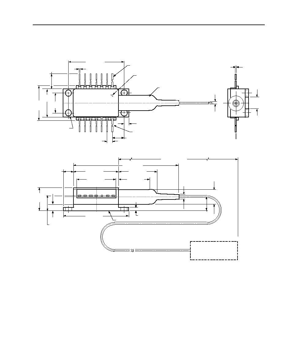
Outline Diagram
Dimensions are in inches and (millimeters). Tolerances are
±
0.005 in. (
±
0.127 mm).
1-520.g
0.820 (20.83)
0.180 (4.56)
0.700 (17.78)
1.180 (29.97)
HEAT SINK
0.215 (5.45)
0.056 (1.42)
0.030 (0.75)
0 .575 (14.6 1)
2.03 (51.6)
39.37 (1000.00)
MIN
0.10
(2.5)
0.260 (6.60)
0.215
(5.47)
REF
0.365
(9.27)
MAX
0.863 (21.91)
0.036
(0.91)
PIN 1
0.078 (1.98)
0.213 (5.40) TYP
0.100 (2.54) TYP
0.105 (2.67) DIA
TYP (4) PLACES
1.025 (26.04)
0.020 (0.51) TYP
0.508
±
0.008
(12.90
±
0.2)
STRAIN
RELIEF
PIN 14
0.350
(8.89)
0.500
(12.70)
0.605
(15.37)
MAX
TRADEMARK, CODE, LASER SERIAL NUMBER,
AND DATE CODE IN APPROX. AREA SHOWN
0.200
(5.08)
0 .10
±
0 .002
(0 .25
±
0.064)