 | –≠–ª–µ–∫—Ç—Ä–æ–Ω–Ω—ã–π –∫–æ–º–ø–æ–Ω–µ–Ω—Ç: D2525P56 | –°–∫–∞—á–∞—Ç—å:  PDF PDF  ZIP ZIP |
Document Outline
- Features
- Applications
- Description
- Controlled Feedback
- Controlled Temperature
- Controlled Power
- Standard Package
- Pin Information
- Absolute Maximum Ratings
- Handling Precautions
- Power Sequencing
- Electrostatic Discharge
- Mounting Instructions
- Characteristics
- Outline Diagram
- High-Power Product
- Ordering Information
- List of Tables
- Table 1. Pin Descriptions
- Table 2. Electrical Characteristics
- Table 3. Optical Characteristics (at 25 ˇC laser temperature)
- Table 4. Ordering Information
- List of Figures
- Figure 1. Polarization-Maintaining Fiber
- Figure 2. Circuit Schematic
- Figure 3. Fillister Head Screw
- Contact Us
Data Sheet
March 2000
Wavelength-Selected D2525P
Isolated DFB Laser Module with PMF
The 1.5
µ
m D2525P Laser Module is available in a 14-pin, her-
metic, butterfly package.
Features
s
ITU wavelengths available from
1529.55 nm --1610.06 nm
s
Integrated optical isolator
s
High-performance, multiquantum-well (MQW),
distributed-feedback (DFB) laser
s
Industry-standard, 14-pin butterfly package
s
Hermetic package
s
InGaAs, PIN photodetector back-facet monitor
s
Polarization-maintaining fiber pigtail
s
For use with lithium niobate modulators
s
High reliability
s
Narrow linewidth
s
High optical power available
Applications
s
Telecommunications
-- SONET/SDH OC-48/STM-16, OC-192/STM-64
-- Extended and ultralong reach
-- Undersea systems
-- Dense WDM systems
s
Digital video
Description
The D2525P family of DFB laser modules is
designed to be used with a lithium niobate external
modulator (see Table 4). The laser module features a
polarization-maintaining fiber (PMF) pigtail, enabling
it to be directly connected to a modulator without the
need of a polarization controller. The PMF maintains
the polarization of the output light to a consistent ori-
entation. This allows the D2525P to be used as a CW
light source for systems requiring extremely low chirp
such as undersea or 10 Gbits/s systems. The module
contains a multiquantum-well (MQW), distributed-
feedback (DFB) laser. This device nominally has an
output power of 10 mW. The wavelength of the laser
can be temperature-tuned for more precise wave-
length selection by adjusting the temperature of the
internal thermoelectric cooler.
Wavelength-Selected D2525P
Data Sheet
Isolated DFB Laser Module with PMF
March 2000
2
2
Lucent Technologies Inc.
Description
(continued)
Controlled Feedback
The module contains an internal optical isolator that sup-
presses optical feedback in laser-based, fiber-optic sys-
tems. Light reflected back to the laser is attenuated a
minimum of 30 dB.
Controlled Temperature
An integral thermoelectric cooler (TEC) provides stable
thermal characteristics. The TEC allows for heating and
cooling of the laser chip to maintain a temperature of 25
∞
C
for case temperatures from ≠40
∞
C to +70
∞
C. The laser
temperature is monitored by the internal thermistor, which
can be used with external circuitry to control the laser chip
temperature.
Controlled Power
An internal, InGaAs, PIN photodiode functions as the back-
facet monitor. The photodiode monitors emission from the
rear facet of the laser and, when used in conjunction with
control circuitry, can control optical power launched into the
fiber. Normally, this configuration is used in a feedback
arrangement to maintain consistent laser output power.
Standard Package
The laser module is fabricated in a 14-pin, hermetic, metal/
ceramic butterfly package that incorporates a bias tee that
separates the dc-bias path from the RF input. The RF input
has a nominal 25
impedance.
The laser module is equipped with
Fujikura
* polarization-
maintaining fiber (PMF). The fiber is PANDA type and is the
same fiber that is used on Lucent Technologies Microelec-
tronics Group's lithium niobate modulators. It has a mode
field diameter of 10.5
µ
m, a cladding diameter of 123
µ
m--
128
µ
m, and a loose tube jacketed fiber 900
µ
m in diame-
ter. The pigtail is terminated with an
ST
Æ
ferrule
. Figure 1
shows the orientation of polarization in the fiber.
Lucent's optoelectronic components are being qualified to
rigorous internal standards that are consistent with
Telcor-
dia Technologies
TR-NWT-000468. All design and manu-
facturing operations are
ISO
ß
9001 certified. The module is
being fully qualified for central office applications.
*
Fujikura
is a registered trademark of Fujikura Ltd.
The
ST
ferrule key is not aligned to slow axis of fiber. Connector is
intended for testing purposes only.
Telcordia Technologies
is a trademark of Bell Communications
Research, Inc.
ß
ISO
is a registered trademark of The International Organization for
Standardization.
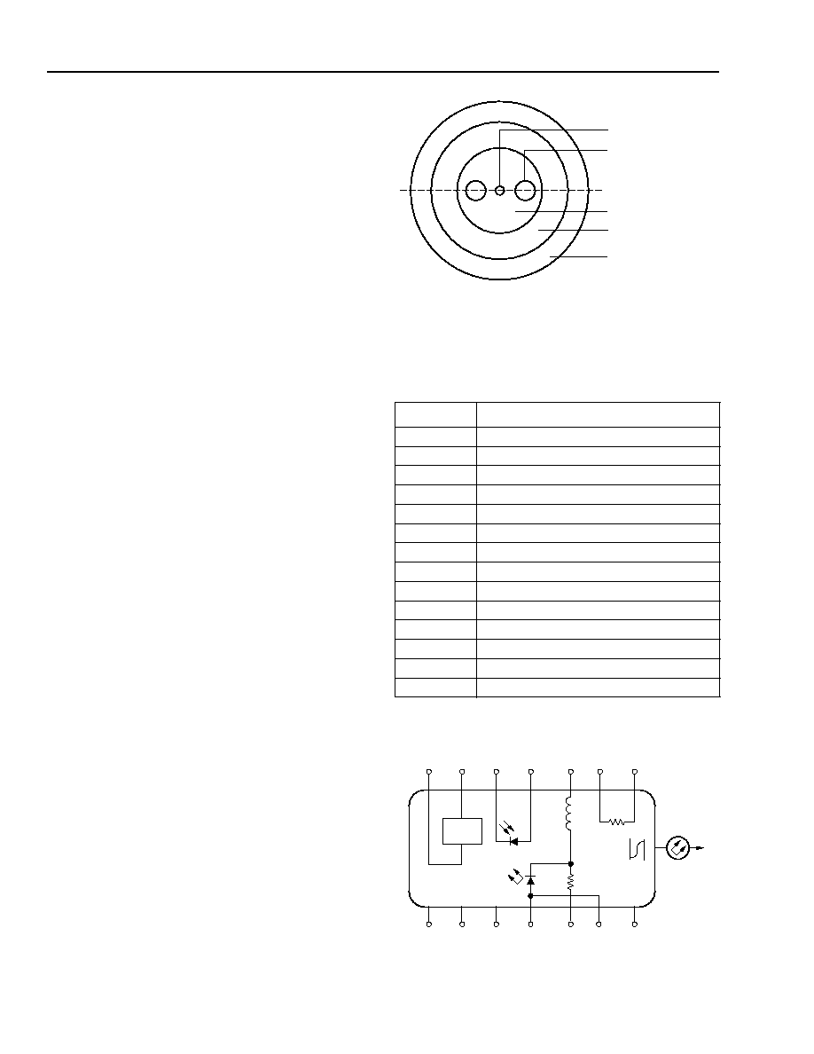
Figure 1. Polarization-Maintaining Fiber
Pin Information
1. A positive current through the thermoelectric heat pump cools the
laser.
2. Both leads should be grounded for optimum performance.
Top view.
Figure 2. Circuit Schematic
Table 1. Pin Descriptions
Pin Name
1 Thermistor
2
Thermistor
3
Laser dc Bias (Cathode) (≠)
4
Back-facet Monitor Anode (≠)
5
Back-facet Monitor Cathode (+)
6
Thermoelectric Cooler (+)
1
7
Thermoelectric Cooler (≠)
1
8
Case Ground
9
Case Ground
10
Case Ground
11
Laser Anode (+)
2
12
RF Laser Input Cathode (≠)
13
Laser Anode (+)
2
14
Case Ground
1-771(C).a
CORE
STRESS ROD
PRINCIPAL POLARIZATION
AXIS
CLADDING
INNER COATING
(SILICON & ACRYLATE)
OUTER COATING
(ACRYLATE OR NYLON)
1-567
TEC
L1
160 nH
ISOLATOR
R1
20
PACKAGE
GROUNDS
≠
+
+
≠
≠
+
≠
+
7
6
5
4
3
2
1
8
9
10
11
12
13
TH
10 k
14
Data Sheet
Wavelength-Selected D2525P
March 2000
Isolated DFB Laser Module with PMF
3
Lucent Technologies Inc.
Absolute Maximum Ratings
Stresses in excess of the absolute maximum ratings can cause permanent damage to the device. These are abso-
lute stress ratings only. Functional operation of the device is not implied at these or any other conditions in excess
of those given in the operations sections of the data sheet. Exposure to absolute maximum ratings for extended
periods can adversely affect device reliability.
* Does not apply to shipping container.
Parameter
Symbol
Min
Max
Unit
Laser Reverse Voltage
V
RLMAX
--
2
V
dc Forward Current
I
FLMAX
--
225
mA
Operating Case Temperature Range
T
C
≠40
70
∞
C
Storage Case Temperature Range*
T
stg
≠40
70
∞
C
Photodiode Reverse Voltage
V
RPDMAX
--
10
V
Photodiode Forward Current
I
FPDMAX
--
2
mA
Handling Precautions
Power Sequencing
To avoid the possibility of damage to the laser module
from power supply switching transients, follow this
turn-on sequence:
1. All ground connections
2. Most negative supply
3. Most positive supply
4. All remaining connections
Reverse the order for the proper turn-off sequence.
Electrostatic Discharge
CAUTION: This device is susceptible to damage as
a result of electrostatic discharge. Take
proper precautions during both han-
dling and testing. Follow guidelines
such as JEDEC Publication No. 108-A
(Dec. 1988).
Lucent employs a human-body model (HBM) for ESD-
susceptibility testing and protection-design evaluation.
ESD voltage thresholds are dependent on the critical
parameters used to define the model. A standard HBM
(resistance = 1.5 k
, capacitance = 100 pF) is widely
used and, therefore, can be used for comparison pur-
poses. The HBM ESD threshold presented here was
obtained using these circuit parameters:
Mounting Instructions
The minimum fiber bend radius is 1.50 in.
To avoid degradation in performance, mount the mod-
ule on the board as follows:
1. Place the bottom flange of the module on a flat heat
sink at least 0.5 in. x 1.180 in. (12.7 mm x 30 mm) in
size. The surface finish of the heat sink should be
better than 32
µ
in. (0.8
µ
m), and the surface flatness
must be better than 0.001 in. (25.4
µ
m). Using ther-
mal conductive grease is optional; however, thermal
performance can be improved by up to 5% if conduc-
tive grease is applied between the bottom flange and
the heat sink.
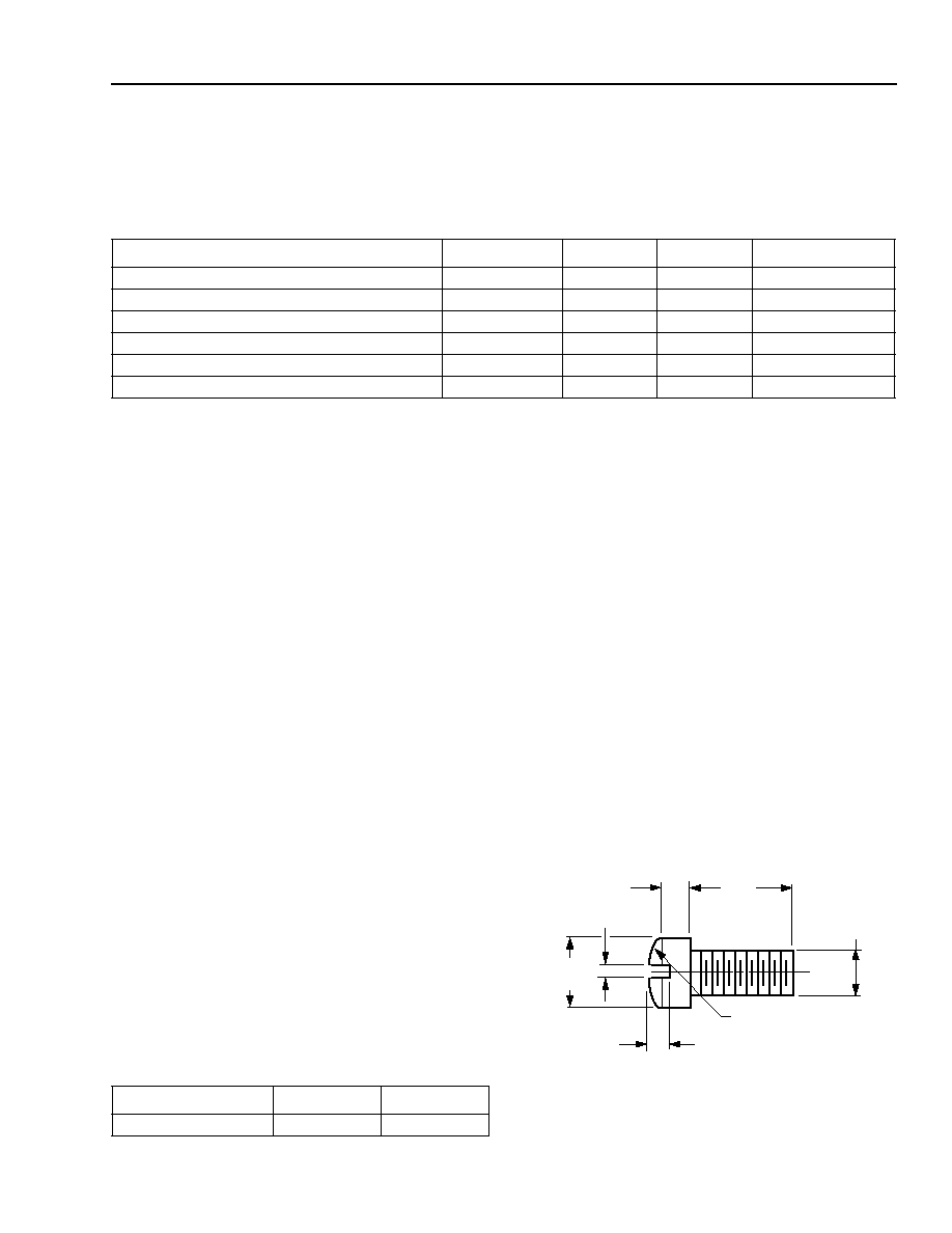
2. Mount four #2-56 screws with Fillister heads
(M2-3 mm) at the four screw hole locations (see Out-
line Diagram). The Fillister head diameter must not
exceed 0.140 in. (3.55 mm). Do not apply more than
1 in.-lb. of torque to the screws.
Note: Dimensions are in inches and (millimeters).
Figure 3. Fillister Head Screw
Parameter Value Unit
Human-body Model
>400
V
0.118
(3.00)
0.062 (1.58)
0.140
(3.56)
0.031 (0.79)
0.129 (3.28) R
0.086
(2.18)
0.041 (1.04)
1-532(C)

Wavelength-Selected D2525P
Data Sheet
Isolated DFB Laser Module with PMF
March 2000
4
Lucent Technologies Inc.
Characteristics
* Standard operating condition is 5.0 V reverse bias.
Ratio of thermistor resistance at 0
∞
C to thermistor resistance at 50
∞
C.
* Custom wavelengths available.
The
ST
ferrule key is not aligned to slow axis of fiber. Connector is intended for testing purposes only.
Table 2. Electrical Characteristics
(at 25
∞
C laser temperature)
Parameter
Symbol
Test Conditions
Min
Typ
Max
Unit
Threshold Current
I
TH
--
--
15
40
mA
Drive Current Above Threshold
--
L
F
= 10 mW
--
--
110
mA
Laser Forward Voltage
V
LF
L
F
= 10 mW (CW)
--
1.3
1.8
V
Monitor Reverse-bias Voltage*
V
RMON
--
3
5
10
V
Monitor Current
I
RMON
P
O
= 10 mW (CW)
0.200
--
--
mA
Monitor Dark Current
I
D
I
F
= 0, V
RMON
= 5 V
--
0.01
0.1
µ
A
Input Impedance
Z
IN
--
--
25
--
Thermistor Current
I
TC
--
10
--
100
µ
A
Resistance Ratio
--
--
9.1
9.6
10.1
--
Thermistor Resistance
R
TH
T
L
= 25
∞
C
9.5
--
10.5
k
TEC Current
I
TEC
T
L
= 25
∞
C, T
C
= 70
∞
C
--
--
1.0 A
TEC Voltage
V
TEC
T
L
= 25
∞
C, T
C
= 70
∞
C --
--
2.0
V
TEC Capacity
T
T
C
= 70
∞
C
50
--
--
∞
C
Table 3. Optical Characteristics (at 25
∞
C laser temperature)
Parameter
Symbol
Test Conditions
Min
Typ
Max
Unit
Peak Optical Output Power
P
P
--
10.0
--
--
mW
Center Wavelength*
(See Table 4.)
C
T
L
= 25
∞
C
CW Wavelength
1529.55
--
1610.06
nm
Line Width (3 dB full width)
CW, P
F
= 10.0 mW
--
2
10
MHz
Relative Intensity Noise
RIN
CW, P
F
= 10.0 mW,
200 MHz < f < 10 GHz
--
--
≠135
dB/Hz
Side-mode Suppression Ratio
SMSR
CW
33
--
--
dB
Optical Isolation
--
T
C
= 0
∞
C to 75
∞
C
30
--
--
dB
Optical Polarization Extinction
Ratio
--
0
∞
C to 75
∞
C
20
--
--
dB
Data Sheet
Wavelength-Selected D2525P
March 2000
Isolated DFB Laser Module with PMF
5
Lucent Technologies Inc.
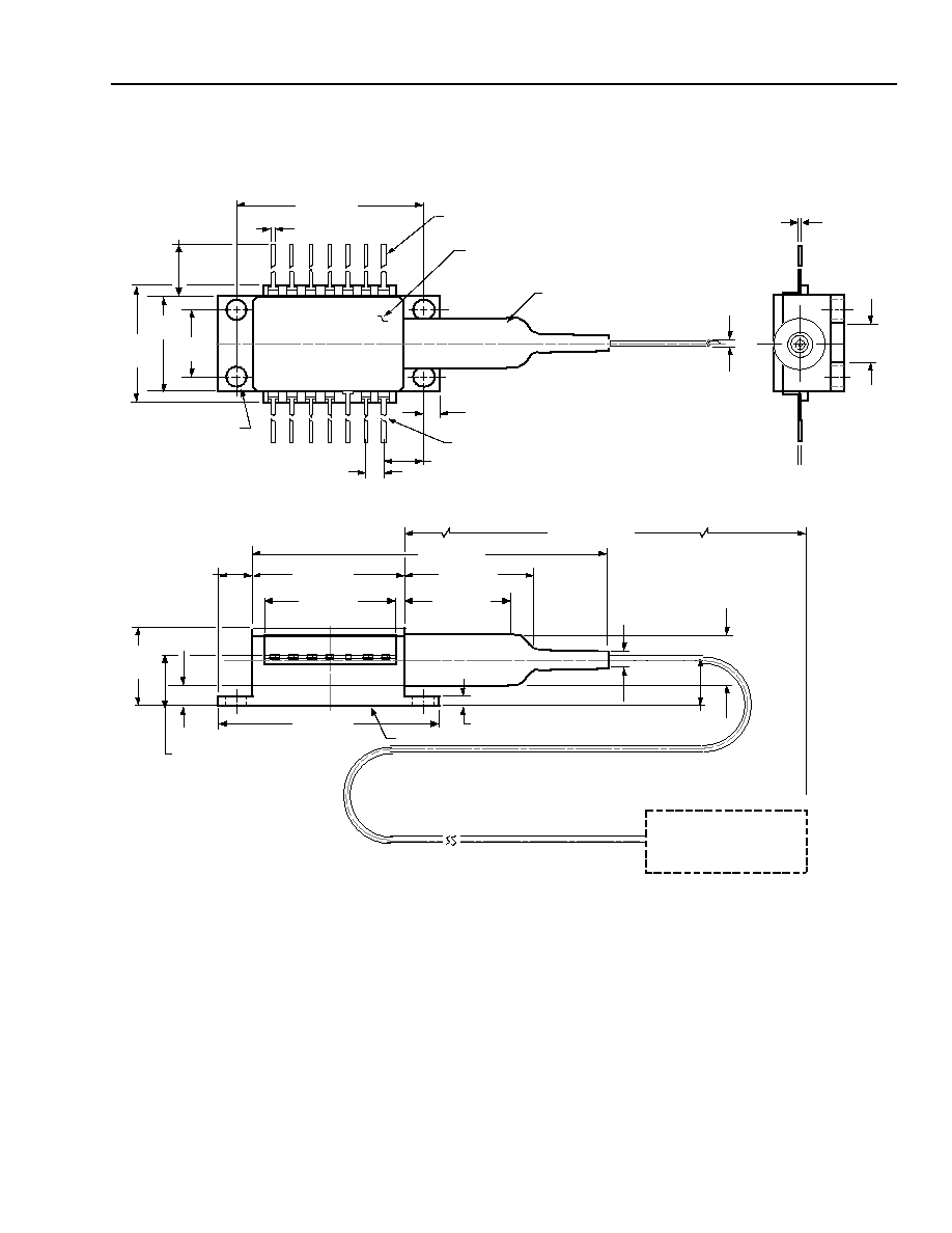
Outline Diagram
Dimensions are in inches and (millimeters). Tolerances are
±
0.005 in. (
±
0.127 mm).
1-520.g
0.820 (20.83)
0.180 (4.56)
0.700 (17.78)
1.180 (29.97)
HEAT SINK
0.215 (5.45)
0.056 (1.42)
0.030 (0.75)
0 .575 (1 4.61)
2.03 (51.6)
39.37 (1000.00)
MIN
0.10
(2.5)
0.260 (6.60)
0.215
(5.47)
REF
0.365
(9.27)
MAX
0.863 (21.91)
0.036
(0.91)
PIN 1
0.078 (1.98)
0 .213 (5.40) TYP
0.100 (2.54) TYP
0.105 (2.67) DIA
TYP (4) PLACES
1.025 (26.04)
0.020 (0.51) TYP
0.508
±
0.008
(12.90
±
0.2)
STRAIN
RELIEF
PIN 14
0.350
(8.89)
0.500
(12.70)
0.605
(15.37)
MAX
TRADEMARK, CODE, LASER SERIAL NUMBER,
AND DATE CODE IN APPROX. AREA SHOWN
0.200
(5.08)
0.10
±
0.002
(0.2 5
±
0.064)