 | –≠–ª–µ–∫—Ç—Ä–æ–Ω–Ω—ã–π –∫–æ–º–ø–æ–Ω–µ–Ω—Ç: D2526G32 | –°–∫–∞—á–∞—Ç—å:  PDF PDF  ZIP ZIP |
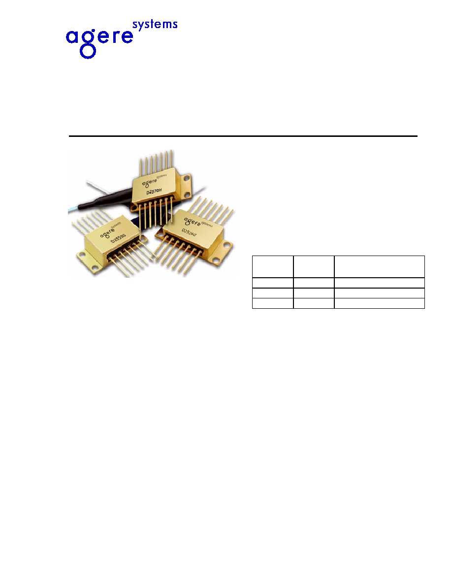
D2570, D2526, D2555 Wavelength-Selected
Direct Modulated Isolated DFB Laser Module
Data Sheet, Rev. 3
July 2001
The 1.5
µ
m D2570, D2526G, and D2555 Laser Modules are
available in a 14-pin, hermetic, butterfly package.
Features
s
ITU wavelengths available from
1528.77 nm --1610.06 nm
s
SONET/SDH compatible up to OC-48/STM-16
s
Temperature tunable for precise wavelength
selection
s
Integrated optical isolator
s
High-performance, multiquantum well (MQW)
distributed-feedback (DFB) laser
s
Industry-standard, 14-pin butterfly package
s
Characterized at 2.488 Gbits/s (NRZ)
s
InGaAs, PIN photodetector back-facet monitor
s
Low threshold current
s
High-reliability, hermetic packaging
s
Excellent long-term wavelength stability can elimi-
nate the need for external wavelength locker
s
Qualified to meet the intent of
Telcordia Technolo-
gies
* 468
*
Telcordia Technologies
is a trademark of Telcordia Technologies,
Inc.
Applications
s
Three direct-modulated DWDM families available
to meet a number of OC-48/STM-16 applications:
-- Extended reach (100 km)
-- Very long reach (170 km)
-- Metro DWDM
-- Digital video
Product Codes
Description
The Direct Modulated Isolated DFB Laser Module
contains an internally cooled, InGaAs, MQW, distrib-
uted-feedback (DFB) laser designed for 1.5
µ
m appli-
cations. The following three direct-modulation DWDM
product families have been established to meet vari-
ous OC-48/STM-16 system applications:
s
D2526-type: designed to be used in OC-48/
STM-16 (2.488 Gbits/s) for extended reach, dense
WDM applications (1800 ps/nm). The wavelength
of the laser can be temperature-tuned for precise
wavelength selection by adjusting the temperature
of the internal thermoelectric cooler.
s
D2555-type: high-performance device designed for
very low dispersion; used in fiber spans exceeding
170 km (3000 ps/nm).
s
D2570-type: high-power, direct-modulated laser
eliminates the need for optical amplifiers in DWDM
many applications.
Product
Code
Peak
Power
Dispersion
Performance
D2570H
10 mW
1800 ps/nm (100 km)
D2526G
2 mW
1800 ps/nm (100 km)
D2555G
2 mW
3000 ps/nm (170 km)
2
Agere Systems Inc.
D2570, D2526G, D2555 Wavelength-Selected
Data Sheet, Rev. 3
Direct Modulated Isolated DFB Laser Module
July 2001
Description
(continued)
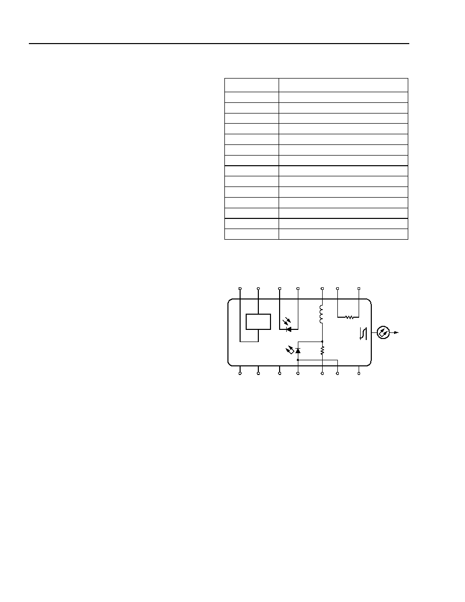
Controlled Feedback
The module contains an internal optical isolator that
suppresses optical feedback in laser-based, fiber-optic
systems. Light reflected back to the laser is attenuated
a minimum of 30 dB.
Controlled Temperature
An integral thermoelectric cooler (TEC) provides stable
thermal characteristics. The TEC allows for heating
and cooling of the laser chip to maintain a temperature
of 25 ∞C for case temperatures from ≠40 ∞C to +70 ∞C.
The laser temperature is monitored by the internal
thermistor, which can be used with external circuitry to
control the laser chip temperature.
Controlled Power
An internal, InGaAs, PIN photodiode functions as the
back-facet monitor. The photodiode monitors emission
from the rear facet of the laser and, when used in con-
junction with control circuitry, can control optical power
launched into the fiber. Normally, this configuration is
used in a feedback arrangement to maintain consistent
laser output power.
Standard Package
The laser module is fabricated in a 14-pin, hermetic,
metal/ceramic butterfly package that incorporates a
bias tee, which separates the dc-bias path from the RF
input. The RF input has a nominal 25
impedance.
The laser module is equipped with
SMF-28
*
type fiber.
The fiber has a 900 µm tight buffer jacket. Various con-
nectors and pigtail lengths are available.
Agere Systems' optoelectronic components are being
qualified to rigorous internal standards that are consis-
tent with
Telcordia Technologies
TR-NWT-000468. All
design and manufacturing operations are
ISO
* 9001
certified. The module is being fully qualified for central
office applications.
*
ISO
is a registered trademark of The International Organization for
Standardization.
SMF-28
is a trademark of Corning Inc.
Pin Information
* A positive current through the thermoelectric heat pump cools the
laser.
Both leads should be grounded for optimum performance.
Top view.
Figure 1. Circuit Schematic
Pin
Name
1
Thermistor
2
Thermistor
3
Laser dc Bias (Cathode) (≠)
4
Back-facet Monitor Anode (≠)
5
Back-facet Monitor Cathode (+)
6
Thermoelectric Cooler (+)*
7
Thermoelectric Cooler (≠)
8
Case Ground
9
Case Ground
10
Case Ground
11
Laser Anode (+)
12
RF Laser Input Cathode (≠)
13
Laser Anode (+)
14
Case Ground
1-567F.b
TEC
L1
160 nH
ISOLATOR
R1
20
PACKAGE
GROUNDS
+
+
≠
≠
+
≠
+
7
6
5
4
3
2
1
8
9
10
11
12
13
TH
10 k
NC
14
≠
Data Sheet, Rev. 3
D2570, D2526G, D2555 Wavelength-Selected
July 2001
Direct Modulated Isolated DFB Laser Module
Agere Systems Inc.
3
Absolute Maximum Ratings
Stresses in excess of the absolute maximum ratings can cause permanent damage to the device. These are abso-
lute stress ratings only. Functional operation of the device is not implied at these or any other conditions in excess
of those given in the performance characteristics of the data sheet. Exposure to absolute maximum ratings for
extended periods can adversely affect device reliability.
* Does not apply to shipping container.
Parameter
Symbol
Min
Max
Unit
Laser Reverse Voltage
V
RLMAX
--
2
V
dc Forward Current
I
FLMAX
--
150
mA
Operating Case Temperature Range
T
C
≠40
70
∞C
Storage Case Temperature Range*
T
stg
≠40
85
∞C
Photodiode Reverse Voltage
V
RPDMAX
--
10
V
Photodiode Forward Current
I
FPDMAX
--
2
mA
Handling Precautions
Power Sequencing
To avoid the possibility of damage to the laser module
from power supply switching transients, follow this turn-
on sequence:
1. All ground connections
2. Most negative supply
3. Most positive supply
4. All remaining connections
Reverse the order for the proper turn-off sequence.
Electrostatic Discharge
CAUTION:
This device is susceptible to damage
as a result of electrostatic discharge.
Take proper precautions during both
handling and testing. Follow guide-
lines such as JEDEC Publication No.
108-A (Dec. 1988).
Agere Systems employs a human-body model (HBM)
for ESD-susceptibility testing and protection-design
evaluation. ESD voltage thresholds are dependent on
the critical parameters used to define the model. A
standard HBM (resistance = 1.5 kæ, capacitance =
100 pF) is widely used and, therefore, can be used for
comparison purposes. The HBM ESD threshold pre-
sented here was obtained using these circuit parame-
ters:
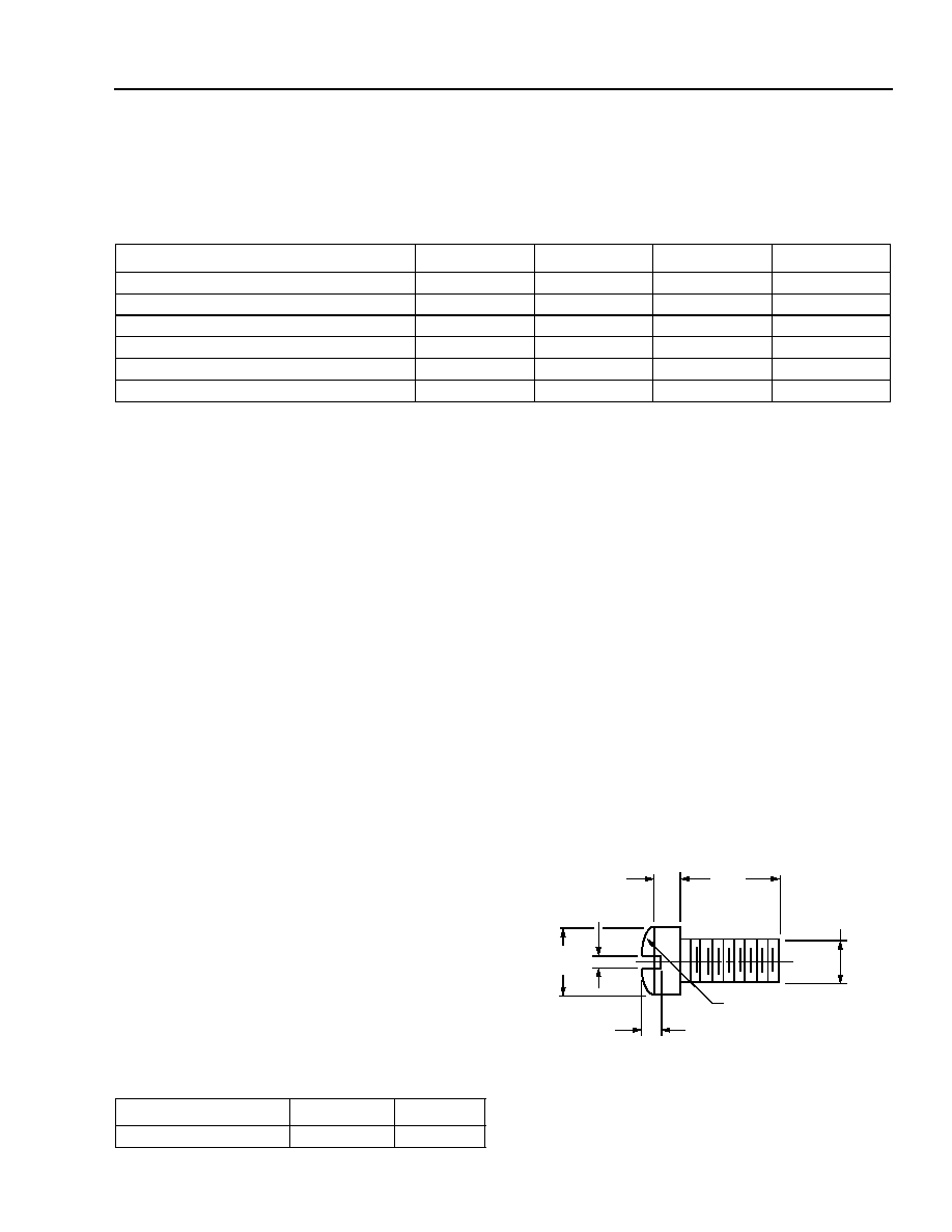
Mounting Instructions
The minimum fiber bend radius is 1.23 in (31.25 mm).
To avoid degradation in performance, mount the mod-
ule on the board as follows:
1. Place the bottom flange of the module on a flat heat
sink at least 0.5 in. x 1.180 in. (12.7 mm x 30 mm) in
size. The surface finish of the heat sink should be
better than 32 µin. (0.8 µm), and the surface flatness
must be better than 0.001 in. (25.4 µm). Using ther-
mal conductive grease is optional; however, thermal
performance can be improved by up to 5% if con-
ductive grease is applied between the bottom flange
and the heat sink.
2. Mount four #2-56 screws with Fillister heads
(M2-3 mm) at the four screw hole locations (see
Outline Diagram). The Fillister head diameter must
not exceed 0.140 in. (3.55 mm). Do not apply more
than 1 in./lb. of torque to the screws.
Figure 2. Fillister Head Screw
Parameter
Value
Unit
Human-body Model
>400
V
1-532
Note: Dimensions are in inches and (millimeters).
0.118
(3.00)
0.062 (1.58)
0.140
(3.56)
0.031 (0.79)
0.129 (3.28) R
0.086
(2.18)
0.041 (1.04)
4
Agere Systems Inc.
D2570, D2526G, D2555 Wavelength-Selected
Data Sheet, Rev. 3
Direct Modulated Isolated DFB Laser Module
July 2001
D2526 Characteristics
Minimum and maximum values are testing requirements. Typical values are characteristics of the device and are
the result of engineering evaluations. Typical values are for information purposes only and are not part of the testing
requirements.
* Standard operating condition is 5.0 V reverse bias.
Ratio of thermistor resistance at 0 ∞C to thermistor resistance at 50 ∞C.
Table 1. Electrical Characteristics (at 25 ∞C laser temperature)
Parameter
Symbol
Test Conditions
Min
Typ
Max
Unit
Slope Efficiency
L
F
= 2 mW (CW)
0.06
0.09
0.13
mW/mA
Threshold Current
I
TH
--
--
14
30
mA
Laser Forward Voltage
V
LF
L
F
= 2 mW (CW)
--
1.3
1.8
V
Laser Submount Temperature
T
LASER
--
20
--
30
∞C
Monitor Reverse-bias Voltage*
V
RMON
--
3
5
10
V
Monitor Current
I
RMON
P
OL
= 1 mW (CW)
0.1
0.3
1.5
mA
Monitor Dark Current
I
D
I
F
= 0, V
RMON
= 5 V
--
0.01
0.1
µ
A
Input Impedance
Z
IN
--
--
25
--
Thermistor Current
I
TC
--
10
--
100
µ
A
Resistance Ratio
--
--
9.1
--
9.6
--
Thermistor Resistance
R
TH
T
L
= 25 ∞C
9.5
--
10.5
k
TEC Current
I
TEC
T
L
= 25 ∞C, T
C
= 70 ∞C
--
0.6
1.0
A
TEC Voltage
V
TEC
T
L
= 25 ∞C, T
C
= 70∞C
--
1.3
2.0
V
TEC Capacity
T
T
C
= 70 ∞C
--
--
50
∞C
Table 2. Optical Characteristics (at 25 ∞C laser temperature)
Parameter
Symbol
Test Conditions
Min
Typ
Max
Unit
Peak Optical Output Power
P
PEAK
--
2.0
--
--
mW
Center Wavelength
(See Table 10.)
c
T
L
= 25 ∞C
CW wavelength
1528.77
--
1610.06
nm
Line Width (3 dB full width)
Modulated at 2.5 Gbits/s
at rated power
--
2
10
MHz
Side-mode Suppression Ratio
SMSR
CW
30
--
--
dB
Optical Isolation
--
T
C
= 0 ∞C to 70 ∞C
30
--
--
dB
Wavelength Drift (EOL)
Tested over
25-year lifetime
--
--
±0.1
nm
Center Wavelength Drift with
Case Temperature
C
/
T
C
0 ∞C
T
C
70 ∞C
--
--
1
pm/∞C
Wavelength Temperature Tuning
Coefficient
--
--
--
0.095
--
nm/∞C
Tracking Error
--
T
C
= ≠20 ∞C/25 ∞C/70 ∞C
--
--
1
dB
Table 3. Dispersion Performance
Parameter
Symbol
Test
Conditions
Min
Typ
Max
Unit
Dispersion Penalty for Extended Reach
DP
1800 ps/nm
--
--
2.0
dB
Data Sheet, Rev. 3
D2570, D2526G, D2555 Wavelength-Selected
July 2001
Direct Modulated Isolated DFB Laser Module
Agere Systems Inc.
5
D2555 Characteristics
Minimum and maximum values are testing requirements. Typical values are characteristics of the device and are
the result of engineering evaluations. Typical values are for information purposes only and are not part of the test-
ing requirements.
* Standard operating condition is 5.0 V reverse bias.
Ratio of thermistor resistance at 0 ∞C to thermistor resistance at 50 ∞C.
Table 4. Electrical Characteristics (at 25 ∞C laser temperature)
Parameter
Symbol
Test Conditions
Min
Typ
Max
Unit
Slope Efficiency
L
F
= 2 mW (CW)
0.05
0.08
0.10
mW/mA
Threshold Current
I
TH
--
--
12
35
mA
Laser Forward Voltage
V
LF
L
F
= 2 mW (CW)
--
1.3
1.8
V
Laser Submount Temperature
T
LASER
--
20
--
30
∞C
Monitor Reverse-bias Voltage*
V
RMON
--
3
5
10
V
Monitor Current
I
RMON
P
OL
= 1 mW (CW)
0.1
0.3
1.9
mA
Monitor Dark Current
I
D
I
F
= 0, V
RMON
= 5 V
--
0.01
0.1
µ
A
Input Impedance
Z
IN
--
--
25
--
Thermistor Current
I
TC
--
10
--
100
µA
Resistance Ratio
--
--
9.1
--
9.6
--
Thermistor Resistance
R
TH
T
L
= 25 ∞C
9.5
--
10.5
k
TEC Current
I
TEC
T
L
= 25 ∞C, T
C
= 70 ∞C
--
0.6
1.0
A
TEC Voltage
V
TEC
T
L
= 25 ∞C, T
C
= 70∞C
--
1.3
2.0
V
TEC Capacity
T
T
C
= 70 ∞C
--
--
50
∞C
Table 5. Optical Characteristics (at 25 ∞C laser temperature)
Parameter
Symbol
Test Conditions
Min
Typ
Max
Unit
Peak Optical Output Power
P
PEAK
--
2.0
--
--
mW
Center Wavelength
(See Table 11.)
c
T
L
= 25 ∞C
CW wavelength
1528.77
--
1563.86
nm
Line Width (3 dB full width)
Modulated at 2.5 Gbits/s
at rated power
--
2
10
MHz
Side-mode Suppression Ratio
SMSR
CW
30
--
--
dB
Optical Isolation
--
T
C
= 0 ∞C to 75 ∞C
30
--
--
dB
Wavelength Drift (EOL)
Tested over
25-year lifetime
--
--
±0.1
nm
Center Wavelength Drift with
Case Temperature
C
/
T
C
0 ∞C
T
C
75 ∞C
--
--
1
pm/∞C
Wavelength Temperature Tuning
Coefficient
--
--
--
0.095
--
nm/∞C
Tracking Error
--
T
C
= ≠20 ∞C/25 ∞C/70 ∞C
--
--
1
dB
Table 6. Dispersion Performance
Parameter
Symbol
Test
Conditions
Min
Typ
Max
Unit
Dispersion Penalty for Extended Reach
DP
3000 ps/nm
--
--
2.0
dB