 | –≠–ª–µ–∫—Ç—Ä–æ–Ω–Ω—ã–π –∫–æ–º–ø–æ–Ω–µ–Ω—Ç: D2547P55 | –°–∫–∞—á–∞—Ç—å:  PDF PDF  ZIP ZIP |
Wavelength-Selected High-Power D2587P-Type (with
Wavelength Locker)/D2547P-Type Isolated DFB Laser Modules
Data Sheet, Rev. 2
July 2001
Featuring wavelength selection and locking capabilities, the
D2587P Laser Module is ideally suited for use with external
lithium niobate modulators, and in high-power (20 mW) appli-
cations.
Features
s
High-performance, multiquantum-well (MQW),
distributed-feedback (DFB) laser
s
D2587P-Type is offered on 50 GHz ITU grid
wavelengths ranging from 1528.77 nm--
1610.06 nm
s
D2547P-Type is offered on 100 GHz ITU grid
wavelengths ranging from 1528.77 nm--
1610.06 nm
s
Polarization-maintaining fiber pigtail
s
For use with lithium niobate modulators
s
High optical power (20 mW, CW)
s
Hermetic, 14-pin package
Applications
s
Telecommunications:
-- Dense WDM
-- SONET/SDH OC-192/STM-64
-- Extended and ultralong reach
-- Undersea systems
s
Digital video
Description
The D2587P-Type DFB laser module is designed for
use with an external lithium niobate modulator and
also in applications where high power (20 mW) is
required.
The use of an internal wavelength locker greatly
enhances long-term reliability and reduces chirp and
mode dispersion when used in conjunction with LN
modulators at OC-192 data rates.
A companion device, the D2547P high-power DFB
laser module, is also designed for use with a lithium
niobate external modulator, but without the use of an
internal wavelength locker.
Wavelength-Selected, High-Power D2587P-Type (with Wavelength
Data Sheet, Rev. 2
Locker)/D2547P-Type Isolated DFB Laser Modules
July 2001
2
2
Agere Systems Inc.
Description
(continued)
Principles of Operation (Controlled Wave-
length)
The single-channel, wavelength-selected DFB (ILM) pack-
age contains internal wavelength-discriminating optics, i.e.,
two etalons and associated photodiodes. The output con-
sists of analog signals suitable for controlling the electrical
current of the thermoelectric cooler (TEC) and the DFB
laser.
Controlled Feedback
The module contains an internal optical isolator that sup-
presses optical feedback in laser-based, fiber-optic sys-
tems. Light reflected back to the laser is attenuated a
minimum of 30 dB.
Controlled Temperature
An integral TEC provides stable thermal characteristics.
The TEC allows for heating and cooling of the laser chip to
maintain a temperature of 25 ∞C for case temperatures from
≠25 ∞C to +70 ∞C. The laser temperature is monitored by
the internal thermistor, which can be used with external cir-
cuitry to control the laser chip temperature.
Controlled Power
An internal, InGaAs, PIN photodiode functions as the back-
facet monitor. The photodiode monitors emission from the
rear facet of the laser and, when used in conjunction with
control circuitry, can control optical power launched into the
fiber. Normally, this configuration is used in a feedback
arrangement to maintain consistent laser output power.
Standard Package
The laser module is fabricated in a 14-pin, hermetic, metal/
ceramic butterfly package that incorporates a bias tee that
separates the dc-bias path from the RF input. The RF input
has a nominal 25
impedance.
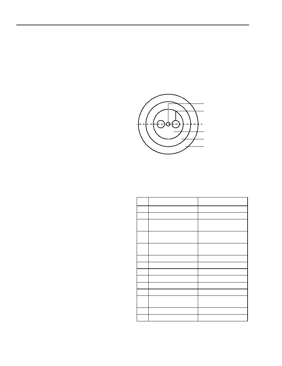
The laser module is equipped with
Fujikura
* polarization-
maintaining fiber (PMF). The fiber is PANDA type and is the
same fiber that is used on the Agere Systems Inc. lithium
niobate modulators. It has a mode field diameter of
10.5
µ
m, a cladding diameter of 125
µ
m ±3
µ
m, and a
loose tube jacketed fiber 900
µ
m in diameter. Figure 1
shows the orientation of polarization in the fiber.
Agere Systems' optoelectronic components are being qual-
ified to rigorous internal standards that are consistent with
Telcordia Technologies
TR-NWT-000468. All design and
manufacturing operations are
ISO
ß
9001 certified. The
module is being fully qualified for central office applications.
*
Fujikura
is a registered trademark of Fujikura Ltd.
Telcordia Technologies
is a trademark of Telcordia Technologies
Inc.
ß
ISO
is a registered trademark of The International Organization for
Standardization.
Figure 1. Polarization-Maintaining Fiber
Pin Information
1. A positive current through the thermoelectric heat pump cools the
laser.
2. Both leads should be grounded for optimum performance.
Table 1. Pin Descriptions
Pin D2587P-Type
D2547P-Type
1 Thermistor
Thermistor
2
Thermistor
Thermistor
3
Laser dc Bias
(Cathode) (≠)
Laser dc Bias
(Cathode) (≠)
4
Back-facet Monitor
Anode (≠)
Back-facet Monitor
Anode (≠)
5
Back-facet Monitor
Cathode (+)
Back-facet Monitor
Cathode (+)
6
TEC (+)
1
TEC (+)
1
7
TEC (≠)
1
TEC (≠)
1
8
Case Ground
Case Ground
9
Photodiode 2 Anode
Case Ground
10
Photodiode 1 Anode
Case Ground
11
Laser Anode (+)
2
Laser Anode (+)
2
12
RF Laser Input
Cathode (≠)
RF Laser Input
Cathode (≠)
13
Laser Anode (+)
2
Laser Anode (+)
2
14
NC
Case Ground
CORE
STRESS ROD
PRINCIPLE POLARIZATION
AXIS
CLADDING
INNER COATING
OUTER COATING
(SILICON & ACRYLATE)
1-771(C).a
Data Sheet, Rev. 2
Wavelength-Selected, High-Power D2587P-Type (with Wavelength
July 2001
Locker)/D2547P-Type Isolated DFB Laser Modules
3
Agere Systems Inc.
Description
(continued)
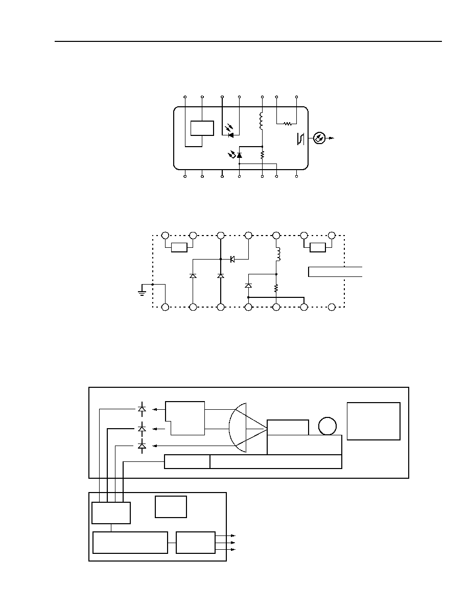
Top view.
Figure 2. D2547P Circuit Schematic
Figure 3. D2587P Circuit Schematic
Block Diagram
1-567
TEC
L1
140 nH
ISOLATOR
R1
20
PACKAGE
GROUNDS
≠
+
+
≠
≠
+
≠
+
7
6
5
4
3
2
1
8
9
10
11
12
13
TH
10 k
NC
14
TEC
R
TH
PM FIBER PIGTAIL
7
6
5
4
3
2
1
8
9
10
11
12
13
14
PD
WAVE
PD
WAVE
PD
POWER
LD
R
RF
RFC
DFB
SILICON SUBMOUNT
THERMOELECTRIC COOLER
DUAL
ETALON
THERMISTOR
ISOLATOR AND
FIBER COUPLING
OPTICS
A TO D
CONVERTER
MICROPROCESSOR
D TO A
CONVERTER
EEPROM
VOLTAGE PROPORTIONAL TO WAVELENGTH
VOLTAGE PROPORTIONAL TO OPTICAL POWER
VOLTAGE PROPORTIONAL TO TEMPERATURE
LASER MODULE
SUGGESTED
ELECTRONICS MODULE (CUSTOMER SUPPLIED)
1-1129(F)
1-1130(F)
Wavelength-Selected, High-Power D2587P-Type (with Wavelength
Data Sheet, Rev. 2
Locker)/D2547P-Type Isolated DFB Laser Modules
July 2001
4
Agere Systems Inc.
Absolute Maximum Ratings
Stresses in excess of the absolute maximum ratings can cause permanent damage to the device. These are abso-
lute stress ratings only. Functional operation of the device is not implied at these or any other conditions in excess
of those given in the operations sections of the data sheet. Exposure to absolute maximum ratings for extended
periods can adversely affect device reliability.
* Does not apply to shipping container.
Parameter
Symbol
Min
Max
Unit
Laser Reverse Voltage
V
RLMAX
--
2
V
dc Forward Current
I
FLMAX
--
225
mA
Operating Case Temperature Range
T
C
≠25
70
∞C
Storage Case Temperature Range*
T
stg
≠40
70
∞C
Photodiode Reverse Voltage
V
RPDMAX
--
10
V
Photodiode Forward Current
I
FPDMAX
--
2
mA
Handling Precautions
Power Sequencing
To avoid the possibility of damage to the laser module
from power supply switching transients, follow this
turn-on sequence:
1. All ground connections
2. Most negative supply
3. Most positive supply
4. All remaining connections
Reverse the order for the proper turn-off sequence.
Electrostatic Discharge
CAUTION: This device is susceptible to damage as
a result of electrostatic discharge. Take
proper precautions during both han-
dling and testing. Follow guidelines
such as JEDEC Publication No. 108-A
(Dec. 1988).
Agere Systems employs a human-body model (HBM)
for ESD-susceptibility testing and protection-design
evaluation. ESD voltage thresholds are dependent on
the critical parameters used to define the model. A
standard HBM (resistance = 1.5 k
, capacitance = 100
pF) is widely used and, therefore, can be used for com-
parison purposes. The HBM ESD threshold presented
here was obtained using these circuit parameters:
Mounting Instructions
The minimum fiber bend radius is 1.0 in. (25.4 mm)
To avoid degradation in performance, mount the mod-
ule on the board as follows:
1. Place the bottom flange of the module on a flat heat
sink at least 0.5 in. x 1.180 in. (12.7 mm x 30 mm) in
size. The surface finish of the heat sink should be
better than 32
µ
in. (0.8
µ
m), and the surface flatness
must be better than 0.001 in. (25.4
µ
m). Using ther-
mal conductive grease is optional; however, thermal
performance can be improved by up to 5% if conduc-
tive grease is applied between the bottom flange and
the heat sink.
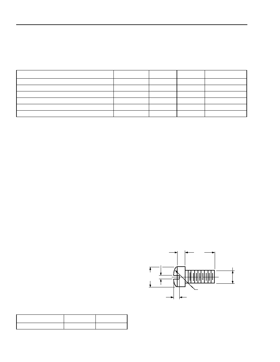
2. Mount four #2-56 screws with Fillister heads
(M2-3 mm) at the four screw hole locations (see Out-
line Diagram). The Fillister head diameter must not
exceed 0.140 in. (3.55 mm). Do not apply more than
1 in.-lb. of torque to the screws.
Note: Dimensions are in inches and (millimeters).
Figure 4. Fillister Head Screw
Parameter Value Unit
Human-body Model
>400
V
0.118
(3.00)
0.062 (1.58)
0.140
(3.56)
0.031 (0.79)
0.129 (3.28) R
0.086
(2.18)
0.041 (1.04)
1-532(C)
Data Sheet, Rev. 2
Wavelength-Selected, High-Power D2587P-Type (with Wavelength
July 2001
Locker)/D2547P-Type Isolated DFB Laser Modules
5
Agere Systems Inc.
Characteristics
Minimum and maximum values are testing requirements. Typical values are device characteristics and are results
of engineering evaluations; they are for information purposes only and are not part of the testing requirements.
* Standard operating condition is 5.0 V reverse bias.
Ratio of thermistor resistance at 0 ∞C to thermistor resistance at 50 ∞C.
* Custom wavelengths available.
The
ST
Æ
ferrule key is not aligned to slow axis of fiber. Connector is intended for testing purposes only.
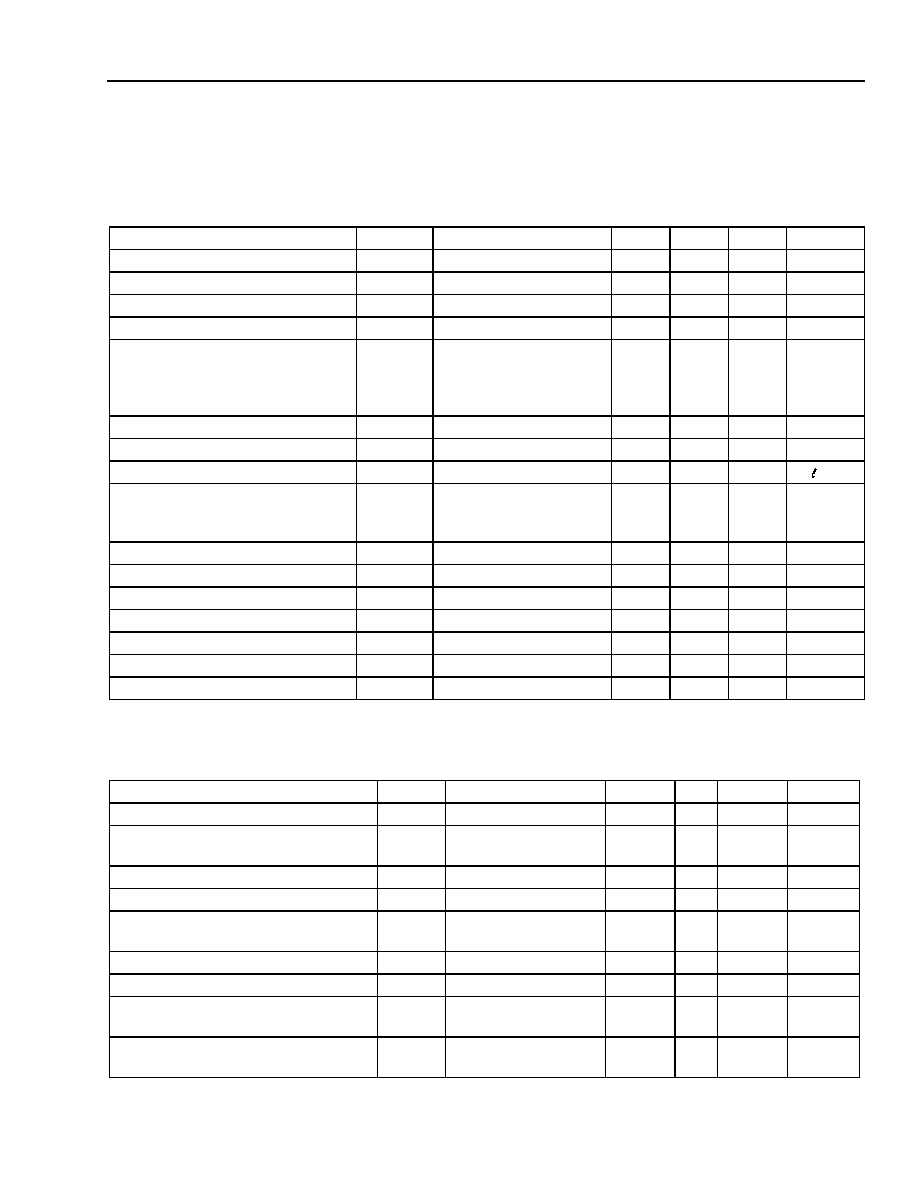
Table 2. D2587-Type Electrical Characteristics (at 25 ∞C laser temperature)
Parameter
Symbol
Test Conditions
Min
Typ
Max
Unit
Threshold Current
I
TH
--
--
15
40
mA
Drive Current
--
L
F
= 20 mW
--
--
165
mA
Laser Forward Voltage
V
LF
L
F
= 20 mW (CW)
--
2
2.5
V
Monitor Reverse-bias Voltage*
V
RMON
--
3
5
10
V
Monitor Current:
Back-facet Monitor
Photodiode 1
Photodiode 2
I
RMON
I
PD1
I
PD2
P
O
= 20 mW (CW)
0.003
0.003
0.003
--
--
--
0.06
0.06
0.06
mA
mA
mA
Monitor Dark Current
I
D
I
F
= 0, V
RMON
= 5 V
--
0.01
0.1
µ
A
Input Impedance
Z
IN
--
--
25
--
Filter Slope
--
--
0.5
--
8
/nm
Frequency Capture Range
--
Measured from
ITU
toward increasing
and
decreasing
15
--
--
GHz
Thermistor Current
I
TC
--
10
--
100
µ
A
Resistance Ratio
--
--
9.1
9.6
10.1
--
Thermistor Resistance
R
TH
T
L
= 25 ∞C
9.5
--
10.5
k
Laser Submount Temperature
T
SET
--
20
--
35
∞C
TEC Current
I
TEC
T
L
= 25 ∞C, T
C
= 70 ∞C
--
--
1.7
A
TEC Voltage
V
TEC
T
L
= 25 ∞C, T
C
= 70 ∞C
--
--
2.8
V
TEC Capacity
T
T
C
= 70 ∞C
--
50
∞C
Table 3. D2587-Type Optical Characteristics (at 25 ∞C laser temperature)
Parameter
Symbol
Test Conditions
Min
Typ
Max
Unit
Peak Optical Output Power
P
P
--
20.0
--
--
mW
Center Wavelength*
(See Ordering Information, page 9.)
C
T
L
= T
SET
C
=
ITU
± 0.1 nm
1528.77
--
1610.06
nm
Line Width (3 dB full width)
CW, P
F
= 20.0 mW
--
2
10
MHz
Side-mode Suppression Ratio
SMSR
CW
35
45
--
dB
Relative Intensity Noise
RIN
CW, P
F
= 20 mW
200 MHz < f < 10 GHz
--
--
≠135
dB/Hz
Optical Isolation
--
T
C
= 0 ∞C to 75 ∞C
30
--
--
dB
Optical Polarization Extinction Ratio
--
0 ∞C to 75 ∞C
20
--
--
dB
FM Efficiency
FM
f
MOD
= 30 kHz,
P
F
= 20 mW
--
100
--
MHz/mA
Wavelength Drift (EOL)
C
Tested over
25-year lifetime
--
--
±2.5
GHz