 | –≠–ª–µ–∫—Ç—Ä–æ–Ω–Ω—ã–π –∫–æ–º–ø–æ–Ω–µ–Ω—Ç: DNCM01 | –°–∫–∞—á–∞—Ç—å:  PDF PDF  ZIP ZIP |

Advance Data Sheet
February 1997
4
Features
s
Compliant with ISO 8802.3
-
1993,
IEEE
*
802.3u
-
1995, and
IEEE
802.3x
-
1995 standards for media
access control:
-- Data transmission and reception rates of
10 Mbits/s at a clock speed of 2.5 MHz or
100 Mbits/s at a clock speed of 25 MHz.
-- State machines for implementing the MII inter-
face support standards-based connectivity to a
variety of physical layer devices (PHYs).
-- Transmits or receives at full- or half-duplex.
-- Supports flow control.
-- Supports both Level 1 and Level 2 VLAN frame
recognition.
s
Extensive network management signals are pro-
vided.
s
Transmit and receive functions can be asynchro-
nously reset with no clocks present.
s
Supports full internal scan test methodology.
s
Designed using
Verilog
HDL.
s
Suitable for Lucent Technologies' 0.5
µ
m and
0.35
µ
m CMOS technology (3 V or 5 V operation).
s
A kit part and evaluation board is planned for eval-
uating the macrocell:
-- The kit part provides a CPU interface for regis-
tered access to configuration and status signals,
management counters, and the MII manage-
ment interface.
-- All configuration and status signals also go to
pins to facilitate prototyping ASIC logic around
the macrocell.
s
Companion macrocells planned:
-- 10 Mbits/s and 100 Mbits/s transceivers.
-- Autonegotiation.
-- Content addressable memory (CAM).
*
IEEE
is a registered trademark of The Institute of Electrical and
Electronics Engineers, Inc.
Verilog
is a registered trademark of Cadence Design Systems,
Inc.
Description
The DNCM01 is an 802.3u
-
1993 compliant macro-
cell capable of both 10 Mbits/s and 100 Mbits/s data
operation. The MAC interfaces with a transceiver
through a media independent interface (MII). The
transmit and receive clocks are 2.5 MHz or 25 MHz,
depending on which speed the PHY is running. The
DNCM01 supports half-duplex and full-duplex opera-
tion. The DNCM01 is capable of transmitting and
receiving MAC control frames, including the PAUSE
opcode. The DNCM01 allows full-duplex flow control
using the PAUSE opcode. The DNCM01 supports
both Level 1 and Level 2 VLAN tagging. The
DNCM01 is able to increase the maximum legal byte
count when frames are transmitted or received with
Level 1 or Level 2 VLAN tags. All transmit and
receive functions can be asynchronously reset with
no clocks present. The DNCM01 can be used with
full internal scan test methodology to ease test devel-
opment time and increase fault coverage.
This data sheet also describes the kit part for evalua-
tion of the DNCM01 macrocell. The kit part has a
CPU interface providing access to registers that
control transmit configuration and report transmit
status and receive status. The kit part configuration
signals are the logic OR of the configuration pins and
configuration register bits. The kit part status signals
are available as both register bits and output pins.
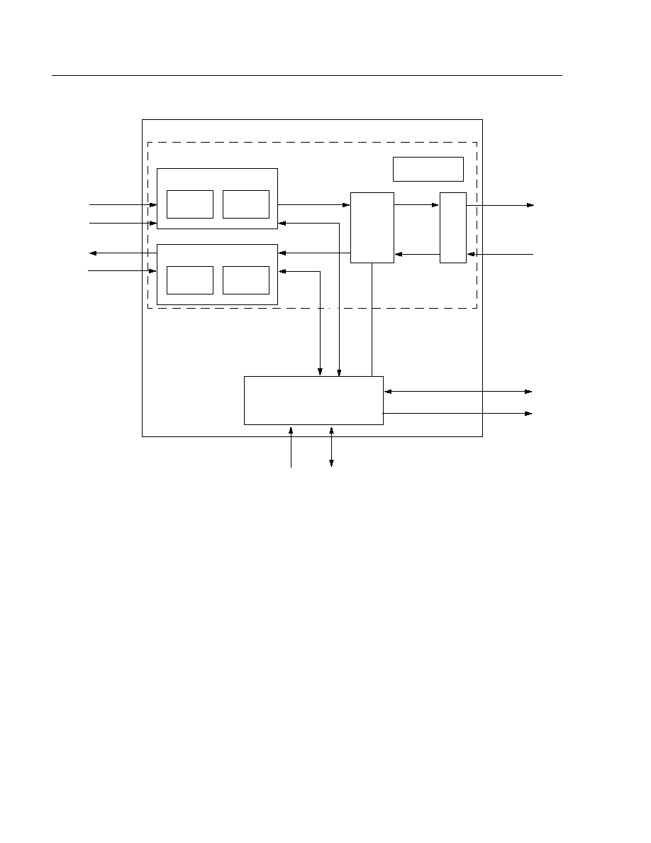
Figure 1 shows the DNCM01 block diagram.
DNCM01
10/100 Ethernet MAC ASIC Macrocell
Note: Advisories are issued as needed to update product information. When using this data sheet for design purposes, please contact
your Lucent Technologies Microelectronics Group Account Manager to obtain the latest advisory on this product.
2
Lucent Technologies Inc.
DNCM01
Advance Data Sheet
10/100 Ethernet MAC ASIC Macrocell
February 1997
4
Description
(continued)
Figure 1. DNCM01 (Shown in Dotted Lines) and DNCM01 Kit Part Block Diagram
TEST LOGIC
REGISTERS
EVENT COUNTER
D
ATA
ADDRESS
TX CONTROL
TX DATA
RX DATA
RX CONTROL
TRANSMIT
DNCM01 MACROCELL
DNCM01 KIT PART
TX DATA
RX DATA
RX CONTR
OL & ST
A
TUS
TX CONTR
OL & ST
A
TUS
TX
CONTROL
TX
STATUS
MII
PORT
FLOW
CONTROL
RECEIVE
RX
CONTROL
RX
STATUS
TX DATA
RX DATA
TX DATA
RX DATA
DUPLEX
PAUSE
MDIO
MDC
5-5113 (F)

Advance Data Sheet
DNCM01
February 1997
10/100 Ethernet MAC ASIC Macrocell
Lucent Technologies Inc.
3
4
Signal Information
Table 1. MII Signal Descriptions (16 Signals)
Signal
Type
Description
COL
I
Collision (Active-High).
Used to indicate a collision between two stations. Assumed to be
active a minimum of two TX_CLK cycles. COL is only sampled during half-duplex transmit
operations when TXE is active, and during the first 64 bit times of interpacket gap time after
any (normal or aborted) transmission if ISQE is active.
CRS
I
Carrier Sense.
Asynchronously asserted by the physical layer when traffic is detected on
the medium.
RX_CLK
I
Receive Clock.
2.5 MHz or 25 MHz receive clock. RX_CLK is sourced by the physical layer
device.
RXD[3:0]
I
Receive Data.
4-bit nibble containing received data. RXD is valid on the rising edge of
RX_CLK.
RX_DV
I
Receive Data Valid.
Used to indicate that the data nibble on RXD has been decoded.
RX_ERR
I
Receive Error.
RX_ERR will be asserted by the PHY when it has detected an error with the
frame currently being received that the DNCM01 may not be able to detect.
TX_CLK
I
Transmit Clock.
2.5 MHz or 25 MHz 50% duty cycle, continuously running. TX_CLK clocks
all transmitter and timer logic. TX_CLK is sourced by the PHY.
TXD[3:0]
O
Transmit Data.
4-bit nibble with data to be transmitted. TXD is driven on the rising edge of
TX_CLK.
TX_ERR
O
Transmit Error.
The DNCM01 does not implement this function at this time.
TX_EN
O
Transmit Enable.
Indicates that a transmission is in progress.
Table 2. Kit Part CPU Interface Signal Descriptions (29 Signals)
Signal
Type
Description
MDC
O
Management Data Clock.
2.5 MHz (maximum) clock to exchange management
data with a device on MDIO.
MDIO
I/O
Management Data.
Bidirectional management data for external device.
RST
I
Reset (Active-High).
Assumed to be asynchronous. Used to reset state machines,
counters, and critical logic in the CPU interface.
CPUSTRB
I
CPU Strobe (Active-Low).
During a write, this signal indicates that the data on
CPUDB[7:0] bus is valid and can be latched into the MAC. During a read, this signal
indicates that the MAC should drive CPUDB[7:0]. CPUAD[2:0] and CPUR/W are
sampled on the falling edge of CPUSTRB.
CPUR/W
I
CPU Read/Write.
Indicates which direction the CPU data bus is in for the current
register or counter access. This signal should be driven high when reading a register/
counter and low when writing a register.
CPURDY
O
CPU Ready (Active-Low).
This signal indicates that the MAC has latched data dur-
ing a write cycle and has placed valid data onto the bus during a read cycle. An
external 1 k
pull-up resistor is required.
CPUDB[15:0]
I
CPU Data Bus.
This data bus is used by the CPU to write and read registers and to
read counters inside the DNCM01.
CPUAD[4:0]
I
CPU Address Bus.
The address bus is used by the CPU to indicate which register/
counter is being read or written.
HCLK
I
Host Clock.
Clock for the DNCM01, supplied by the host.
SELPLL
I
Select PLL.
Selects the divisor of the host clock for the MDC clock of the MII inter-
face.
High--high-speed HCLK, MDC = HCLK/32
Low--low-speed HCLK, MDC = HCLK/16

4
Lucent Technologies Inc.
DNCM01
Advance Data Sheet
10/100 Ethernet MAC ASIC Macrocell
February 1997
4
Signal Information
(continued)
Table 3. TX Control Signal Descriptions (31 Signals)
Signal
Type
Description
TXRST
I
Transmit Reset (Active-High).
Assumed to be asynchronous. Used to reset state
machines and critical logic in the transmitter.
INVCRC
I
Invert CRC (Active-High).
Used to invert the polarity of the 32-bit CRC polynomial. The
normal CRC is inverted prior to transmission. If INVCRC is high, the normal CRC is re-
inverted prior to sending, forcing a CRC error.
APNDCRC
I
Append CRC (Active-High)
. Used to control if a 32-bit CRC polynomial is appended to
the end of transmitted packet. If high, the CRC is appended.
RETRY[1:0]
I
Retry.
Used to control the total number of attempts (initial + retries after collision) the
MAC makes to transmit a packet. The total attempts follow the table below:
RETRY1
RETRY0
Attempts
0
0
16
0
1
8
1
0
4
1
1
1
BSEL
I
Backoff Select (Active-High).
Used to control whether the binary backoff algorithm is
used during collision handling. If BSEL is high, the backoff algorithm is not used. The
transmitter jams for 32 TX_CLK cycles and attempts to retransmit after 96 bit times (nor-
mal IFG). If low, the transmitter follows the normal binary backoff algorithm following a
collision.
DEFER
I
Defer (Active-High).
Used to force the transmitter to abort a transmission attempt if it
has deferred for more than 24,288 TX_CLK cycles. Deferring starts when the transmitter
is ready to transmit, but is prevented from doing so because CRS is active. Defer time is
not cumulative. If the transmitter defers for 10,000 bit times, then transmits, collides,
backs off, and then has to defer again after completion of backoff, the deferral timer
resets to 0 and restarts. If DEFER is low, the transmitter defers indefinitely.
MFDUP
I
MAC Full Duplex (Active-High).
Used to control half- or full-duplex operation. When
MFDUP is low, the COL input is monitored and the binary backoff algorithm is employed
if collisions occur during transmission. When MFDUP is low and CRS is asserted while
the MAC's own packet is being transmitted, the receiver is not enabled since the received
packet is the MAC's own transmitted packet. When MFDUP is high, all packets are
received regardless of the status of TXE.
TXREQ
I
Transmit Request (Active-High).
Used to request a packet transmission. TXREQ is a
handshake signal and should be held high until TXACK is activated by the transmitter.
TXREQ should not be activated until TXEOP is returned by the transmitter.
TXABORT
I
Transmit Abort (Active-High).
Used to stop a transmission ungracefully. The transmit-
ter immediately terminates a transmission if this input is set. TXABORT should be held
high for two or more TX_CLK cycles. When a packet is aborted during preamble, the pre-
amble is completed and the APNDCRC and INVCRC inputs are followed. If TXABORT is
activated during transmission, transmission immediately stops, and the APNDCRC and
INVCRC inputs are followed.

Advance Data Sheet
DNCM01
February 1997
10/100 Ethernet MAC ASIC Macrocell
Lucent Technologies Inc.
5
4
Signal Information
(continued)
Table 3. TX Control Signal Descriptions (31 Signals)
(continued)
Signal
Type
Description
TXACK
O
Transmit Acknowledge (Active-High).
Used in conjunction with TXREQ as a hand-
shake. When TXACK goes high in response to TXREQ, TXREQ can be deactivated.
TXINPROG
O
Transmit in Progress (Active-High).
This output is set high if the MAC is currently
transmitting preamble, data, or CRC. TXINPROG will not be active if the transmitter is
deferring in collision backoff.
TXEOD
I
Transmit End of Data (Active-High).
Used to end a transmit operation normally.
TXEOD should activate one clock after the DMA receives a TXLD from the transmitter.
The transmitter loads and transmits that byte, and then transmits CRC according to the
status of APNDCRC and INVCRC.
TXSOP
O
Transmit Start of Packet.
Active for 1 bit time at the start of preamble. Valid on the
positive edge of TX_CLK.
TXDIN[7:0]
I
Transmit Data In.
TXDB is loaded into the transmit shift register on the falling edge of
the TXLD input. The LSB is transmitted first.
TXLD
O
Transmit Load Data (Active-High).
Used to tell that the MAC transmitter requires a
byte of data for transmission. TXDB[7:0] is strobed into the transmit shift register on the
falling edge of TXLD. Valid on the positive edge of TX_CLK.
TXEOP
O
Transmit End of Packet (Active-High).
Used to indicate the end of transmit operation.
The operation may end because of successful transmission, excessive collisions,
excess deferral or an TXABORT command. TXEOP is active for 1 TX_CLK cycle.
Transmit statistics, except for SQE, should be latched on the falling edge of TXEOP.
Valid on positive edge of TX_CLK. SQE should be latched on the falling edge of
TXSOP of the following frame.
CNTRL
I
Send Control Frame.
Used to indicate that the current frame is a control frame. The
destination will be the reserved multicast address. The control opcode and PAUSE time
data will be sent to TXDB[7:0] and the transmit control signals will be valid. This signal
may be deactivated after CNTRLACK.
CNTRLACK
O
Control Acknowledge (Active-High).
Used in conjunction with CNTRL as a hand-
shake. When CNTRLACK goes high in response to CNTRL, CNTRL may be deacti-
vated.
ISQE
I
Ignore SQE Test.
Used to ignore the SQE signal from the PHY during the first 64 bit
times of interframe gap. If high, the SQE error flag will not be set.
FCSOP
O
Flow Control Start of Packet (Active-High).
Activates for 1 TXC at the start of trans-
mission of a flow control frame, synchronous with TXC.
FCEOP
O
Flow Control End of Packet (Active-High).
Activates for 1 TXC at the end of trans-
mission of a flow control frame, synchronous with TXC. Transmit statistics can be
strobed using FCEOP as a strobe.
PREAM[1:0]
I
Preamble.
Used to control the number of preamble bits that will be transmitted before
the start of frame delimiter.
PREAM1
PREAM0
Preamble
0
0
56 bits
0
1
48 bits
1
0
40 bits
1
1
8 bits

6
Lucent Technologies Inc.
DNCM01
Advance Data Sheet
10/100 Ethernet MAC ASIC Macrocell
February 1997
4
Signal Information
(continued)
Table 4. RX Control Signal Descriptions (13 Signals)
Signal
Type
Description
RXBYTE[7:0]
O
Receive Byte (Active-High).
An 8-bit latch that holds a byte of receive data. Valid on
positive edge of RX_CLK.
RXRST
I
Receive Reset (Active-High).
Assumed to be asynchronous. Used to reset state
machines and critical logic in the receiver. Valid on positive edge of RX_CLK.
RXSOP
O
Receive Start-of-Packet (Active-High).
Indicates that the receiver has detected that
CRS is high and that RX_CLK is being generated. Receive statistics are reset on the
falling edge of RXSOP. Valid on the positive edge of RX_CLK.
RXSFD
O
Receive Start-of-Frame Delimiter (Active-High).
Indicates that a start-of-frame
delimiter has been detected in a received packet (10101011). Valid on positive edge of
RX_CLK.
RXEOP
O
Receive End-of-Packet (Active-High).
Indicates that CRS has gone inactive and that
receive statistics are valid for reading. Valid on positive edge of RX_CLK.
RXBVLD
O
Receive Byte Valid (Active-High).
Active for 1 bit time after a new receive byte has
been loaded into the RXBYTE[7:0] latch. Valid on positive edge of RX_CLK.
Table 5. TX Status Signal Descriptions (19 Signals)
Signal
Type
Description
TXBYTE
O
Transmit Byte.
Indicates that a complete byte of data or CRC has been transmit-
ted. TXBYTE is valid for 1 TX_CLK bit time immediately after the last bit of a byte
was transmitted. Valid on the positive edge of TX_CLK.
EXDEF
O
Excessive Deferral (Active-High).
Indicates transmission ended because of
waiting for more than 24,288 bit times for the medium to become not busy. Valid
on the positive edge of TX_CLK.
DEF
O
Deferral (Active-High).
Indicates that a transmission deferred for 1 bit time to
24,288 bit times during transmission. Valid on the positive edge of TX_CLK.
SCOL
O
Single Collision (Active-High).
Indicates that there was one collision during
transmission of the previous packet. Valid on the positive edge of TX_CLK.
MCOL
O
Multiple Collisions (Active-High).
Indicates that there was more than one colli-
sion during the transmission of the previous packet. Valid on the positive edge of
TX_CLK.
CERR
O
Collision Error (Active-High).
Indicates that the previous transmission was
stopped because of excessive collisions as allowed by the RETRY[1:0] inputs.
SCOL and MCOL are also valid if CERR is active. Valid on the positive edge of
TX_CLK.
COLDET
O
Collision Detected (Active-High).
Indicates that a collision has been detected.
This signal is active from the time of a collision until the completion of the 32-bit
jam sequence. The COL signal is monitored only when the transmitter is actively
transmitting data. Valid on the positive edge of TX_CLK.

Advance Data Sheet
DNCM01
February 1997
10/100 Ethernet MAC ASIC Macrocell
Lucent Technologies Inc.
7
4
Signal Information
(continued)
Table 5. TX Status Signal Descriptions (19 Signals)
(continued)
Signal
Type
Description
LCRS
O
Loss of Carrier (Active-High).
Indicates that the CRS input was inactive for one
or more bit times while the transmitter is active and in half duplex. Valid on the
positive edge of TX_CLK.
ABORTED
O
Transmission Aborted (Active-High). Indicates that a transmission has been
aborted before completion. Valid on the positive edge of TX_CLK.
LATE
O
Late Collision (Active-High). Indicates that a collision occurred more than
512 bit times from the start of a transmission. The start of transmission is defined
as the transmission of the first bit of preamble. Valid on the positive edge of
TX_CLK.
TCNTRL
O
MAC Control Frame Transmitted. Indicates that the last packet sent was a MAC
control frame. Valid on the positive edge of TX_CLK.
TPAUSE
O
PAUSE Frame Transmitted. Indicates that the last MAC control frame sent was a
PAUSE frame. Valid on the positive edge of TX_CLK.
SQEFAIL
O
SQE Test Failed (Active-High). Indicates that a COL signal was not detected
during the first 6.4
µ
s of interframe gap following a transmit attempt. SQE is inac-
tive if the ISQE input is high. Valid on the positive edge of TX_CLK.
SQEVALID
O
SQE Valid. This signal goes active 6.4
µ
s after the end of transmission to indicate
to the DMA that the SQEFAIL signal contains valid information.
PAUSEACTIVE
O
Pause Active (Active-High). Active while the transmitter is blocked from trans-
mitting after the reception of a PAUSE command. This output is synchronous with
TXC.
TX_VLAN2
O
Two-Level VLAN Frame. When this signal is set, the current transmission is
tagged with a VLAN2 ID. The thirteenth and fourteenth bytes at the frame are
compared to the two-level VLAN tag register. This signal is set if there is a non-
zero match.
TX_VLAN1
O
One-Level VLAN Frame. When this signal is set, the current transmission is
tagged with a VLAN1 ID. The thirteenth and fourteenth bytes at the frame are
compared to the one-level VLAN tag register. This signal is set if there is a non-
zero match.
TXBROAD
O
Transmit Broadcast (Active-High). Active from TXEOP (FCEOP) to TXSOP
(FCSOP) of the following frame, synchronous with TXC. TXEOP can be used to
strobe TXBROAD. TXBROAD is active if the transmitted frame has a destination
address of all 1s.
TXMULT
O
Transmit Multicast (Active-High). Active from TXEOP (FCEOP) to TXSOP
(FCSOP) of the following frame, synchronous with TXC. TXEOP can be used to
strobe TXMULT. TXMULT is active if the transmitted frame has a destination
address with the first transmitted address bit a 1 and at least one of the following
47 address bits a 0.

8
Lucent Technologies Inc.
DNCM01
Advance Data Sheet
10/100 Ethernet MAC ASIC Macrocell
February 1997
4
Signal Information
(continued)
Table 6. RX Status Signal Descriptions (35 Signals)
Signal
Type
Description
IFG
O
Short IFG (Active-High). Indicates that the interframe gap prior to the start of
the packet was less than 76 bit times. Valid on the positive edge of RX_CLK.
RXJAB
O
Receive Jabber Error (Active-High). Indicates that receive packet length was
greater than 1518 bytes, and the packet had a bad CRC or FAE. Valid on the pos-
itive edge of RX_CLK.
FAE
O
Frame Alignment Error (Active-High). Indicates a packet was received with a
frame alignment error. An FAE occurs when the resultant remainder from the divi-
sion between the number of bits in a frame and eight is nonzero (nonintegral
number of octets), the CRC is invalid, and the octet counters are greater than or
equal to 64 and less than or equal to 1518. Valid on the positive edge of RX_CLK.
Dribble bits have no effect.
CRC
O
CRC Error (Active-High). Indicates a packet was received with a bit count hav-
ing a mod 8 remainder equal to 0, and that packet had an incorrect CRC. Valid on
the positive edge of RX_CLK.
RUNT
O
Runt Packet (Active-High). Indicates a packet was received with a byte count
(including CRC) <64, and the packet had a good CRC. Valid on the positive edge
of RX_CLK.
FRAG
O
Fragment (Active-High). Indicates a packet was received with a byte count
(including CRC) <64, and the packet had a bad CRC or FAE. Valid on the positive
edge of RX_CLK.
LONG
O
Frame Long Error (Active-High). Indicates that the received packet's length
was greater than 1518 bytes, and the packet had good CRC. Valid on the positive
edge of RX_CLK.
PHYS
O
Received Physical Address (Active-High). Indicates that the first bit of the
received packet was 0, and that at least 6 bytes of data were received. Valid on
the positive edge of RX_CLK.
MULT
O
Received Multicast Address. Indicates that the first bit of the received packet
was 1, all address bits were not 1, and that at least 6 bytes of data were received.
Valid on the positive edge of RX_CLK.
BROAD
O
Received Broadcast Address. Indicates that all 48 address bits of a received
frame are 1. Valid on the positive edge of RX_CLK.
NULPKT
O
Null Packet. Indicates that CRS and RX_CLK were active for some time and that
no SFD sequence was detected. Valid on the positive edge of RX_CLK.
RXCOUNT[15:0]
O
Received Byte Counter. A 16-bit counter that indicates the number of full bytes
received in the current packet. This counter freezes at FFFF bytes. This counter
clears on read.
RCNTRL
O
MAC Control Frame Received. Indicates that the last packet received was a
valid MAC control frame. Valid on the positive edge of RX_CLK.
RUNSUP
O
Unsupported Opcode Received. Indicates that the last MAC control frame
received had an unsupported opcode. Valid on the positive edge of RX_CLK.
RPAUSE
O
PAUSE Frames Received. Indicates that the last control frame received has a
multicast address, length/type field, and opcode for the PAUSE operation. Valid
on the positive edge of RX_CLK.
RX_VLAN2
O
Two-Level VLAN Frame. When this signal is set, the current reception is tagged
with a VLAN2 ID. The 13th and 14th bytes at the frame are compared to the two-
level VLAN tag register. This signal is set if there is a nonzero match.

Advance Data Sheet
DNCM01
February 1997
10/100 Ethernet MAC ASIC Macrocell
Lucent Technologies Inc.
9
4
Signal Information
(continued)
Table 6. RX Status Signal Descriptions (35 Signals) (continued
)
Signal
Type
Description
RX_VLAN1
O
One-Level VLAN Frame. When this signal is set, the current reception is tagged
with a VLAN1 ID. The 13th and 14th bytes at the frame are compared to the one-
level VLAN tag register. This signal is set if there is a nonzero match.
EPAUSE
O
Early Pause (Active-High). A frame with the control multicast address, the con-
trol type/length field, and the pause opcode was received. This output is valid
prior to EOP.
ECNTRL
O
Early Control. Active from the 18th byte of an incoming control frame until
RXSOP of the following frame, synchronous with RXC.
RXEROUT
O
Receive Error Output (Active-High). Active from RXEOP of an incoming frame
to RXSOP of the next frame, synchronous with RXC. RXEOP can be used to
strobe RXEROUT. RXEROUT will activate if the RX_ERR input from the MII acti-
vates for 1 or more clocks while RX_DV is high.
Table 7. Control Frame Configuration Signal Descriptions (101 Signals)
Signal
Type
Description
CFD0[15:0]
I
Control Frame Destination Address 0. These signals represent the first 16 bits
of the 48-bit reserved multicast address for control frames.
CFD1[15:0]
I
Control Frame Destination Address 1. These signals represent the second
16 bits of the 48-bit reserved multicast address for control frames.
CFD2[15:0]
I
Control Frame Destination Address 2. These signals represent the third
16 bits of the 48-bit reserved multicast address for control frames.
CFT
I
Control Frame Type. The assigned 2-octet length/type field of a MAC control
frame.
CFO
I
Control Frame Opcode. The 2-octet MAC control opcode field indicating the
MAC control function.
CFTV1
I
VLAN Type 1 Type Field. The assigned 2-octet length/type field of a VLAN type
1 packet.
CFTV2
I
VLAN Type 2 Type Field. The assigned 2-octet length/type field of a VLAN type
2 packet.
CFS0[15:0]
I
Control Frame Source Address 0. These signals represent the first 16 bits of
the 48-bit source address for control frames.
CFS1[15:0]
I
Control Frame Source Address 1. These signals represent the second 16 bits
of the 48-bit source address for control frames.
CFS2[15:0]
I
Control Frame Source Address 2. These signals represent the third 16 bits of
the 48-bit source address for control frames.
CFDATA
I
Control Frame Data. Two octets provided for the data field inside the control
frame.

10
DNCM01
Advance Data Sheet
10/100 Ethernet MAC ASIC Macrocell
February 1997
4
Signal Information
(continued)
Table 8. Test Signal Descriptions (2 Signals)
Signal
Type
Description
TSTMODE
I
Test Mode. Used to modify the terminal count of transmit counters to speed up
testing. When TSTMODE is high, the counters are modified as follows:
Counter
Normal Count
Modified Count
51.2
µ
s timer
512
3
DEFER timer
24288
242
RSTRNDM
I
Reset Random Binary Backoff Algorithm. Used to reset the random backoff timer.
Netlist Order
Inputs, Outputs:TXRST, RXRST, TX_CLK, HCLK,
COL, MFDUP, RETRY, BSEL,
PREAM, ISQE, DEFER, TXREQ,
TXEOD, TXABORT, APNDCRC,
INVCRC, TSTMODE,
RSTRNDM, TXDIN, CNTRL,
CFD0, CFD1, CFD2, CFT, CFO,
CFTV1, CFTV2, CFS0, CFS1,
CFS2, CFDATA, TXACK, TXIN-
PROG, TXLD, TXEOP, LATE,
EXDEF, DEF, COLDET, SCOL,
MCOL, CERR, LCRS, SQEFAIL,
SQEVALID, TXBYTE, TXSOP,
ABORTED, TXD, TX_EN,
TX_ERR, RX_CLK, CRS, RX_DV,
RX_ERR, RXD, RXCOUNT,
RXSOP, RXSFD, RXEOP,
RXBVLD, RXJAB, FAE, CRC,
RUNT, FRAG, LONG, PHYS,
MULT, BROAD, IFG, NULPKT,
RXBYTE, CNTRLACK, RCNTRL,
RUNSUP, RPAUSE, PAUSEAC-
TIVE, FCSOP, FCEOP, TXMULT,
TXBROAD, EPAUSE, RXEROUT,
TX_VLAN1, TX_VLAN2,
RX_VLAN1, RX_VLAN2,
TCNTRL, TPAUSE, ECNTRL
Functional Description
Transmitter
The transmitter in the DNCM01 is made up of a state
machine, a preamble-jam counter block, a transmit
counters block, a 32-bit CRC generator, a 15-bit
deferral time-out counter, and a transmit serializer.
Frame Transmission
A transmit operation is initiated by the host activating
TXREQ. When TXREQ is recognized, the DNCM01
responds by activating TXACK. After TXREQ, the
transmitter holds TXACK active until TXREQ is
dropped; until the transmitter successfully sends the
packet; or until transmit is aborted because of exces-
sive collisions, excessive deferral, or host-initiated
abort.
Transmission begins when the intergap timer has
expired. If the timer has reached 9.6
µ
s (0.96
µ
s at
100 Mbits/s) prior to TXREQ, packet transmission
begins immediately. If TXREQ is given before 6.4
µ
s
(0.64
µ
s at 100 Mbits/s) of intergap and the DNCM01
was the station transmitting, the new packet begins
transmission at 9.6
µ
s (0.96
µ
s at 100 Mbits/s) regard-
less of CRS. If the timer is greater than 6.4
µ
s (0.64
µ
s
at 100 Mbits/s) and CRS is high, the transmission
defers until CRS is deasserted, at which time, the
9.6
µ
s (0.96
µ
s at 100 Mbits/s) timer activates, and
transmission starts after time-out.
Transmitter operation is controlled by a state machine
modeled after the one shown in Appendix B of the
1993 version of ISO 8802.3 standard.
Immediately prior to starting preamble, the DNCM01
sends a 1 TX_CLK signal, TXSOP, to the host. Another
DNCM01 output, TXINPROG, is valid while the
DNCM01 is actively transmitting.

Advance Data Sheet
DNCM01
February 1997
10/100 Ethernet MAC ASIC Macrocell
Lucent Technologies Inc.
11
4
Functional Description
(continued)
Preamble is programmable by PREAM[1:0] to be 32,
40, 48, or 56 bits, and an 8-bit SFD (10101011) is
appended after preamble. The DNCM01 has no
address registers, so source and destination
addresses must be included in the byte stream sent by
the host. The DNCM01 does not provide automatic
frame padding for frames less than 64 bytes.
At the end of preamble, the DNCM01 sends one
TX_CLK signal, TXLD, to the host. The DNCM01
strobes in the byte to be transmitted on the falling edge
of TXLD. After the first TXLD, subsequent requests are
sent every two TX_CLK cycles. After the last byte is
sent by the host, the host signifies the end of data by
activating TXEOD for one TX_CLK. After transmitting
the last byte, the DNCM01 appends the CRC to the
data stream if the CRC input to the DNCM01 is high.
The CRC can also be sent inverted if desired (to force
a bad CRC) by setting the INVCRC input high. After
completing transmission, the DNCM01 sends a
TXEOP signal to the host. All transmit statistics (SCOL,
MCOL, CERR, ABORTED, EXDEF, etc.) except SQE
can be latched on the falling edge of TXEOP. During
transmission, the DNCM01 activates TXBYTE for one
TX_CLK for each byte it sends. For an N byte packet,
the DNCM01 sends N + 4 TXBYTE signals if CRC was
appended.
After successful transmission, the DNCM01 monitors
the COL input for an SQE test signal if the ISQE input
is low. COL is monitored for the first 64 bits of intergap
time. If SQE test is not observed, the SQE output is set
to 1 and held until the next TXSOP signal. A control
output SQEFAIL is valid from 6.4
µ
s (0.64
µ
s at
100 Mbits/s) until TXSOP of the next packet, and SQE
is valid when SQEFAIL is high.
If another TXREQ is sent before 6.4
µ
s (0.64
µ
s at
100 Mbits/s) of intergap time, the MAC attempts to
transmit the new packet regardless of CRS. CRS
normally does not activate during this time if all stations
are observing proper protocol, so this should be an
infrequent event.
Collision Retransmission
The DNCM01 handles collision situations in accor-
dance with ISO 8802.3. The RETRY[1:0] inputs select
1, 4, 8, or 16 attempts to transmit, with RETRY[1:0] =
00 giving the standard 16 attempts. The standard
backoff algorithm is used. The DNCM01 has a 12-bit
pseudorandom shift register counter which free runs.
The counter can be frozen for periods of time by driving
the RSTRNDM input high. This signal can be driven by
a decoded chip enable or some other unique signal to
increase the randomness of a group of 10/100 Base-T
MACs.
When a collision is sensed, a 32-bit jam pattern
(1111 . . .) is transmitted. After the jam pattern
completes, N bits of the counter (N depends on the
collision number) is dumped into a 10-bit counter which
in turn decrements by the turnover of the 51.2
µ
s
(5.12
µ
s at 100 Mbits/s) timer. Backoff lasts until the
10-bit counter reaches 0. Transmission is retried if the
9.6
µ
s (0.96
µ
s at 100 Mbits/s) timer has expired or is
deferred until CRS deactivates and the 9.6
µ
s (0.96
µ
s
at 100 Mbits/s) timer expires. If a deferral lasts longer
than 24,288 bit times, the DNCM01 aborts transmis-
sion if the DEFER input is set high. This also applies to
a deferral at the start of regular transmission. Deferral
is not cumulative; it restarts from 0 each time a deferral
state is entered. If a packet cannot be transmitted after
making the selected number of attempts, the transmit
is aborted and the CERR output is activated. If a colli-
sion occurs during preamble, the preamble-SFD
sequence is completed prior to jamming.
The COLDET output indicates the presence of a colli-
sion situation to the host. If a late collision (after 512 bit
times, including preamble and SFD) occurs, the LATE
output is set high. The MAC does not abort after a late
collision is detected. This must be done by the host. If
the DNCM01 detects a collision while transmitting, it
always sends a jam pattern prior to deactivating TXE
regardless of the status of TXABORT, TXEOD, or the
status of the collision counter. The host should always
reset its transmit stack if the COLDET output goes high
to ensure complete packet transmission.
The BSEL input can be used to override the backoff
timer if desired. If BSEL is 1 and a collision is detected,
the DNCM01 jams and retransmits when the 9.6
µ
s
(0.96
µ
s at 100 Mbits/s) IFG has expired. If the MFDUP
is high (full-duplex mode), the DNCM01 ignores the
collision signal.
Receiver
The DNCM01 receiver consists of a state machine,
CRC generator, 64 Kbyte counter, and deserializer.
When the DNCM01 detects a low-to-high transition of
CRS, and RX_CLK is operating, it sends an RXSOP
signal to the host. The first 10 bits of preamble sensed
are ignored. After the first 10 bits of preamble, an SFD
sequence (10101011) causes an RXSFD signal to be
sent. After RXSFD, the receiver buffers each byte of
received data. After assembling the byte, one RX_CLK
time RXBVLD signal is sent to the host. The host has
two RX_CLK times to read the byte from the RXBYTE
register. When CRS falls, the receiver monitors the

12
Lucent Technologies Inc.
DNCM01
Advance Data Sheet
10/100 Ethernet MAC ASIC Macrocell
February 1997
4
Functional Description
(continued)
result of CRC calculated on the last full byte. If CRC
falls on a byte boundary, the packet is either good or
has a CRC error. If CRS falls on a nonbyte boundary,
but the last full byte received had a good CRC, it is a
good packet with dribble bits. If CRS falls on a nonbyte
boundary and the CRC was bad, it is a frame alignment
error. The receiver informs the host of the end of the
packet by activating the RXEOP output for 1 RX_CLK.
Other receive statistics include RXJAB (packet with
> 1518 bytes and a CRC or FAE), LONG (>1518 bytes
with good CRC), NUL (CRS high for an indefinite time
with no SFD), and others which are described in the
signal list. Receive statistics are valid from RXEOP to
the next RXSOP.
If the MFDUP input is low (half duplex), the receiver
ignores any packets that start while TXE is high, to
avoid buffering one's own transmitted packet. In order
to prevent glitches on CRS during a collision situation
from affecting the receiver, the receiver ignores high-to-
low transitions of CRS if a packet reception is in
progress and the COL signal is present. If MFDUP is
high (full duplex), the receiver ignores the COL signal.
The DNCM01 does not have any physical address
registers or multicast address registers, nor does it
have any multicast address group detection logic. It
does have three outputs PHYS, MULT, and BROAD,
one of which activates after 6 bytes of data have been
received. PHYS means the first bit of data in the packet
was 0, MULT means the first bit was 1 and at least 1 of
the next 47 was 0, and BROAD is a 48-bit address of
all 1s.
Flow Control
The DNCM01 allows full-duplex control using the
PAUSE operation. The PAUSE operation is used to
inhibit data transmission of data frames for a specified
period of time. A PAUSE operation consists of the
frame containing the globally assigned multicast
address (in the address block: 01-80-C2-00-00-01
through 01-80-C2-00-00-0F), the PAUSE opcode, and
a parameter indicating the quanta of slot time (512 bit
times) to inhibit data transmissions. The PAUSE
parameter may range from 0 to 65,535 slot times. A
DNCM01 receiving a frame with the multicast address
and PAUSE opcode will inhibit data frame transmis-
sions of the length of time indicated. If a PAUSE
request is received while a transmission is in progress,
then PAUSE will take effect after the transmission is
complete. Control frames are received and processed
by the MAC and are passed on. The signal EPAUSE
can be used to prevent having a control frame passed
up to upper layers.
To send PAUSE frames, the DNCM01 may transmit
control frames. To transmit a control frame, assert the
CNTRL signal. Hold the CNTRL signal active until the
DNCM01 responds by activating CNTRLACK. The
DNCM01 will automatically begin the transmission of a
control frame after the 96 bit time IFG expires. If the
transmitter is in the process of transmitting a frame, the
control frame will be transmitted when the normal
transmit is complete and the IFG timer expires. The
DNCM01 will assert the TXINPROG signal until the
transmission of the control frame has completed. The
DNCM01 may transmit control frames if it has been
paused by another station.
VLAN Support
The DNCM01 recognizes transmit and receive frames
that are tagged with either one-level or two-level VLAN
IDs. The DNCM01 compares the thirteenth and four-
teenth bytes of transmit and receive frames to the
contents of both the one-level VLAN tag register and
the two-level VLAN tag register. If a nonzero match is
made, the DNCM01 identifies the frame as either a
one-level or two-level VLAN frame, but not both. Upon
recognizing that a frame has a VLAN tag, counter
thresholds are adjusted to account for the extra bytes
that the VLAN tag adds to the frame. If the frame is a
one-level VLAN frame, the maximum length of a good
packet is changed from 1518 bytes to 1522 bytes. If the
frame is a two-level VLAN frame, the maximum length
of a good packet is changed from 1518 bytes to
1538 bytes. In both cases, status signals are set indi-
cating which VLAN frame occurred.
Timing
The kit part's address and data bus should have 20 ns
setup and 10 ns hold time in respect to the falling edge
of the CPUSTRB signal. Register writes are synchro-
nized to the appropriate clock; this may delay CPURDY.
CPUSTRB should be held for one HCLK after
CPURDY is deasserted.
Transmit input signals require 20 ns setup and 10 ns
hold time. Transmit output signals are valid after a
maximum of 20 ns after the appropriate positive edge
of TXCLK. During a transmission, TXDATA is strobed in
on the falling edge of TXLD. TXBYTE will be valid for
one TXCLK after a byte has been transmitted. Transmit
status signals are valid from TXEOP of the current
packet until TXSOP of the next packet.

Advance Data Sheet
DNCM01
February 1997
10/100 Ethernet MAC ASIC Macrocell
Lucent Technologies Inc.
13
4
Functional Description
(continued)
Receive input signals require 20 ns setup and 10 ns
hold time. Receive output signals are valid after a
maximum of 20 ns after the appropriate positive edge
of RXCLK. Receive status signals are valid from
RXEOP of the current packet until RXSOP of the next
packet. Early Pause will be valid after the sixteenth
byte of a pause frame has been received.
General Information
The DNCM01 is approximately 8500 gates without
scan logic or the CPU interface of the kit part. It exists
as a fully synthesizable
Verilog
*
HDL behavioral/state
table description and can easily be modified for specific
customer requirements.
DNCM01 Kit Part
CPU Interface
A CPU interface (Figure 2) is included in the DNCM01
kit part. This interface allows access to the registers
and counters of the DNCM01 kit part. This interface
also has a reset signal that will reset the state
machines, counters, and critical logic in the CPU inter-
face.
Registers and Counters
The DNCM01 kit part contains transmit configuration,
transmit status, and receive status registers. The
transmit configuration register provides access to
internal signals that control the transmission options for
the DNCM01 kit part. The transmit status and receive
*
Verilog is a registered trademark of Cadence Design Systems, Inc.
status registers provide access to output signals that
describe the results of the last transmitted or received
frame.
The DNCM01 kit part contains control frame registers
that hold the reserved multicast destination address,
source address, reserved length/type field, control
opcode, and data. The DNCM01 will assemble a frame
from the contents of the control frame registers.
The DNCM01 kit part contains receive and collision
counters. The receive counter is a 16-bit register that
counts the number of valid bytes received in the current
packet by the DNCM01 kit part. This counter freezes at
0xFFFF bytes. The receive counter clears on read. The
collision counter is a 16-bit counter that reports the
number of collisions on a transmit attempt. Valid counts
are 0 through 15. When the number of collisions is
equal to the retry attempt value, Retry[1:0], an exces-
sive collision error occurs. The collision counter clears
on read.
Flow Control
The DNCM01 kit part implements flow control by
receiving and sending PAUSE (control) frames. The
DNCM01 kit part contains the necessary registers and
logic to automatically send control frames. These
control frame registers hold the reserved multicast
destination address, source address, reserved length/
type field, control opcode, and data. The DNCM01 will
automatically transmit a control frame when the
CNTRL signal is asserted. The DNCM01 kit part will
assemble a frame from the contents of the control
frame registers. The TXINPROG signal will be
asserted while the transmission is in progress. The
DNCM01 kit part handles the transfer of data from the
control registers to the transmit data bus of the
DNCM01.

14
Lucent Technologies Inc.
DNCM01
Advance Data Sheet
10/100 Ethernet MAC ASIC Macrocell
February 1997
4
DNCM01 Kit Part
(continued)
Table 9. DNCM01 Registers and Counters
Table 10. MII Address Register
CPU AD[4:0]
Register/Counter
Read/Write
MII Registers
00000
MII address register
Read/write
00001
MII data register
Read/write
DNCM01 Registers
00010
Configuration register
Read/write
00011
Transmit status register
Read
00100
Receive status register
Read
00101--00111
Control frame destination address register
Read
01000--01010
Control frame source address register
Read/write
01011
Control frame length/type register
Read
01100
Control frame opcode register
Read/write
01101
Control frame data register
Read/write
DNCM01 Counters
01110
Receive counter
Read
01111
Collision counter
Read
10000
VLAN1 type/length field
Read/write
10001
VLAN2 type/length field
Read/write
15
14
13
12
11
10
9
8
7
6
5
4
3
2
1
0
Phy4
Phy3
Phy2
Phy1
Phy0
Reg4
Reg3
Reg2
Reg1
Reg0
Reserved
Write
Busy
Bit
Name
Description
15:11
Phy[4:0]
Phy Address. These bits tell which of the 32 possible PHY devices are being accessed.
10:6
Reg[4:0]
MII Register. These bits select the desired MII register in the selected PHY device.
5:2
--
Reserved. These bits are reserved and must be set to 0.
1
Write
MII Write. Setting this bit tells the PHY that this will be a write operation using the MII data
register. If this bit is not set, this will be a read operation, placing the data in the MII data
register.
0
Busy
MII Busy. This bit should read a logic 0 before writing to the MII address and MII data reg-
isters. This bit must also be set to 0 during a write to the MII address register. During a MII
register access, this bit will then be set to signify that a read or write is in progress. The MII
data register should be kept valid until this bit is cleared during a PHY write operation. The
MII data register is invalid until this bit is cleared by the MAC during a PHY read operation.
The MII address register should not be written to until this bit is cleared.

Advance Data Sheet
DNCM01
February 1997
10/100 Ethernet MAC ASIC Macrocell
Lucent Technologies Inc.
15
4
DNCM01 Kit Part
(continued)
Table 11. MII Data Register
Table 12. Configuration Register
15
14
13
12
11
10
9
8
7
6
5
4
3
2
1
0
Data15 Data14 Data13 Data12 Data11 Data10 Data9 Data8 Data7 Data6 Data5 Data4 Data3 Data2 Data1 Data0
Bit
Name
Description
15:0
DATA[15:0] MII Data. 16-bit data value read from the PHY after a MII read operation. 16-bit data value
to be written to the PHY before a MII write operation.
15
14
13
12
11
10
9
8
7
6
5
4
3
2
1
0
TxRST RxRST MFDUP Reserved InvCRC AppCRC Retry1 Retry0 RSTRNDM Bsel Reserved ISQE Defer Reserved
Bit
Name
Description
15
TxRST
Transmit Reset. Setting this bit causes the reset of transmit state machines and counters.
This bit is self-clearing.
14
RxRST
Receive Reset. Setting this bit causes the reset of receive state machines and counters.
This bit is self-clearing.
13
MFDUP
Full Duplex. This bit sets either half- or full-duplex operation. When MFDUP is high, the
COL input is ignored during packet transmission and monitored during intergap delay for
the presence of SQE, if the ISQE signal is not active. When MFDUP is high, all packets are
received regardless of the status of TXE.
12
--
Reserved. This bit is reserved and must be set to 0.
11
InvCRC
Invert CRC. This bit inverts the polarity of the 32-bit CRC polynomial. The normal CRC is
inverted prior to transmission. If INVCRC is high, the normal CRC is reinverted prior to
sending, forcing a CRC error.
10
ApndCRC
Append CRC. When this bit is set, a 32-bit CRC polynomial is appended to the end of a
transmitted packet.
9, 8
Retry[1:0]
Retry Attempt Select. These bits set the total number of attempts (initial and retries after
collision) the MAC makes to transmit a packet. The total attempts follow the table below:
RETRY1
RETRY0
Attempts
0
0
16
0
1
8
1
0
4
1
1
1
7
RSTRNDM
Reset Random Binary Backoff Algorithm. Set and then clear this bit to reset the random
binary backoff algorithm. This is a test feature.
6
Bsel
Backoff Select. When this bit is set, the backoff algorithm is not used. After a collision
occurs during transmission, the transmitter jams for 32 TX_CLK cycles and attempts to re-
transmit after 9.6
µ
s (0.96
µ
s at 100 Mbits/s) of intergap time. If low, the transmitter follows
the normal binary backoff algorithm following a collision.
5:3
--
Reserved. These bits are reserved and must be set to 0.
2
ISQE
Ignore SQE Test. Used to ignore the SQE signal from the PHY during the first 6.4
µ
s at
10 Mbits/s of interframe gap. If high, the SQE error flag will not be set.
1
Defer
Abort After Max Deferral. When Defer is set, the transmitter aborts a transmission
attempt if it has deferred for more than 24,233 TX_CLK cycles. Deferring starts when the
transmitter is ready to transmit, but is prevented from doing so because CRS is active.
Defer time is not cumulative. If the transmitter defers for 10,000 bit times, then transmits
and collides, backs off, and then has to defer again after completion of backoff, the deferral
timer resets to 0 and restarts. If DEFER is low, the transmitter defers indefinitely.
0
Reserved
Reserved. This bit is reserved and must be set to 0.

16
Lucent Technologies Inc.
DNCM01
Advance Data Sheet
10/100 Ethernet MAC ASIC Macrocell
February 1997
4
DNCM01 Kit Part
(continued)
Table 13. Control Frame Destination Address Register
Table 14. Control Frame Source Address Register
Table 15. Control Frame Length/Type Register
Table 16. Control Frame Opcode Register
Table 17. MAC Control Parameters Register
Bit
Name
Description
47:0
CDEST
Control Frame Destination Address. The 48-bit reserved multicast address register for
control frames.
Bit
Name
Description
47:0
CSOURCE
Control Frame Source Address. The 48-bit individual address register of the station
sending the frame.
Bit
Name
Description
15:0
CTYPE
Control Frame Length/Type. The assigned 2-octet length/type field of a MAC control
frame.
Bit
Name
Description
15:0
COPCODE
Control Frame Opcode. The 2-octet MAC control opcode field indicating the MAC con-
trol function.
Bit
Name
Description
15:0
CPARAM
MAC Control Parameters. Two octets are provided to hold MAC control opcode-specific
parameters.

Advance Data Sheet
DNCM01
February 1997
10/100 Ethernet MAC ASIC Macrocell
Lucent Technologies Inc.
17
4
DNCM01 Kit Part
(continued)
Table 18. Transmit Status Register
15
14
13
12
11
10
9
8
7
6
5
4
3
2
1
0
Reserved TXMULT TXBROAD TX_VLAN2 TX_VLAN1 LATE ExDef DEF SCOL MCOL CERR LCRS SQEFAIL Reserved Aborted
Bit
Name
Description
15:14
--
Reserved. These bits are reserved and must be set to 0.
13
TXMULT
Transmit Multicast. TXMULT is active if the transmitted frame has a destination address
with the first transmitted address bit a 1 and at least one of the following 47 address bits a
0. TXBROAD and TXMULT are mutually exclusive. Valid on the positive edge of TX_CLK.
12
TXBROAD
Transmit Broadcast. TXBROAD is active if the transmitted frame has a destination
address of all 1s. Valid on the positive edge of TX_CLK.
11
TX_VLAN2
Two-Level VLAN Frame. When this bit is set, the current transmission is tagged with a
VLAN2 ID. The thirteenth and fourteenth bytes at the frame are compared to the two-level
VLAN tag register. This bit is set if there is a nonzero match.
10
TX_VLAN1
One-Level VLAN Frame. When this bit is set, the current transmission is tagged with a
VLAN1 ID. The thirteenth and fourteenth bytes at the frame are compared to the one-
level VLAN tag register. This bit is set if there is a nonzero match.
9
LATE
Late Collision. This bit is set when a collision occurred more than 512 bit times
(64 bytes) from the start of a transmission. The start of the transmission is defined as the
transmission of the first bit of preamble.
8
ExDef
Excessive Deferral. This bit is set if the transmission ended because of excessive defer-
ral of over 24,288 bit times if the defer bit is selected in the transmit configuration register.
7
DEF
Deferred. This bit is set if a transmission deferred for 1 to 24,288 bit times during trans-
mission.
6
SCOL
Single Collision. This bit is set if the frame being transmitted collided once and was then
transmitted successfully. This bit is not set if the transmission is aborted due to excess
collisions or there are multiple collisions. This bit is not valid if the MAC is configured for
full duplex.
5
MCOL
Multiple Collisions. This bit is set if the frame being transmitted collided more than once
and was then transmitted successfully. This bit is not set if the transmission is aborted
due to excess collisions or there is a single collision. This bit is not valid if the MAC is con-
figured for full duplex.
4
CERR
Collision Error. This bit is set if the previous transmission was stopped because of
excessive collisions as allowed by the RETRY[1:0] inputs. SCOL and MCOL are also
valid if CERR is active.
3
LCRS
Loss of Carrier. This bit is set if the CRS input was inactive for one or more bit times
while the transmitter was active.
2
SQEFAIL
SQE Test Failed. Indicates that a COL signal was not detected during the first 6.4
µ
s of
interframe gap following a transmit attempt. SQE is inactive if the ISQE input is high.
1
--
Reserved. These bits are reserved and must be set to 0.
0
Aborted
Frame Aborted. This bit is set if a transmission has aborted before completion.

18
Lucent Technologies Inc.
DNCM01
Advance Data Sheet
10/100 Ethernet MAC ASIC Macrocell
February 1997
4
DNCM01 Kit Part
(continued)
Table 19. Receive Status Register
15
14
13
12
11
10
9
8
7
6
5
4
3
2
1
0
IFG NulPkt Reserved RX_VLAN2 RX_VLAN1
Reserved RxJab FAE CRC RUNT FRAG LONG Phys Mult Broad
Bit
Name
Description
15
IFG
Short IFG. This bit is set if the interframe gap prior to the start of the packet was less than
9.6
µ
s (0.96
µ
s at 100 Mbits/s).
14
NulPkt
Null Packet. This bit is set if CRS and RX_CLK were active for some time, but no SFD
sequence was detected.
13
--
Reserved. These bits are reserved and must be set to 0.
12
RX_VLAN2
Two-Level VLAN Frame. When this bit is set, the current reception is tagged with a
VLAN2 ID. The thirteenth and fourteenth bytes at the frame are compared to the two-level
VLAN tag register. This bit is set if there is a nonzero match.
11
RX_VLAN1
One-Level VLAN Frame. When this bit is set, the current reception is tagged with a
VLAN1 ID. The thirteenth and fourteenth bytes at the frame are compared to the one-level
VLAN tag register. This bit is set if there is a nonzero match.
10:9
--
Reserved. These bits are reserved and must be set to 0.
8
RxJab
Receive Jabber Error. This bit is set when the current frame is greater than 1518 bytes,
and the packet has a bad CRC or a FAE.
7
FAE
Frame Alignment Error. This bit is set if the current frame being received has a frame
alignment error. An FAE occurs when the resultant remainder from the division between
the number of bits in the frame and eight is nonzero (nonintegral number of octets), the
FCS is invalid, and the octet counters are greater than or equal to 64 and less than or
equal to 1518.
6
CRC
CRC Error. This bit is set if a packet was received with a bit count with a mod 8 remainder
equal to 0, and that packet has an incorrect CRC.
5
RUNT
Runt Packet. This bit is set if a packet was received with a byte count (including CRC)
<64, and the packet had a good CRC.
4
FRAG
Fragment. This bit is set if a packet was received with a byte count (including CRC) <64,
and the packet had a bad CRC or a FAE.
3
LONG
Frame Long Error. This bit is set if the received packet's length was greater than
1518 bytes, and the packet had a good CRC.
2
Phys
Received Physical Address. This bit is set if the first bit of the received packet was 0, and
at least 6 bytes of data were received.
1
Mult
Received Multicast Address. This bit is set if the first bit of the received packet was 1, all
address bits were not 1, and at least 6 bytes of data were received.
0
Broad
Received Broadcast Address. This bit is set if all 36 address bits were 1.

Advance Data Sheet
DNCM01
February 1997
10/100 Ethernet MAC ASIC Macrocell
Lucent Technologies Inc.
19
4
DNCM01 Kit Part
(continued)
Application Information
DNCM01 Demo Board
Features
s
Switchable base address
s
16-bit MAC register bus
s
8-bit FIFO bus
s
MII interface
s
Hardware interrupt (based on RXEOP, resettable by software)
s
Eight board commands:
-- Transmit a single packet
-- Start continuous transmissions
-- Read receive FIFO
-- Write transmit FIFO
-- Clear transmit FIFO
-- Reset
-- Clear interrupt
-- Send control frame
Table 20. Counters
Counter
Description
Receive
Received Bytes. 16-bit counter, indicates the number of full bytes received in the current packet.
This counter freezes at FFFF bytes. This counter clears on read.
Collision
Collisions Detected. 5-bit counter, reports the number of collisions on a transmit attempt. Valid
counts are 0 through 15. When the number of collisions is equal to the retry attempt value,
Retry[1:0], an excessive collision error occurs and the jam pattern is transmitted. This counter
clears on read or next transmission.
20
Lucent Technologies Inc.
DNCM01
Advance Data Sheet
10/100 Ethernet MAC ASIC Macrocell
February 1997
4
Application Information
(continued)
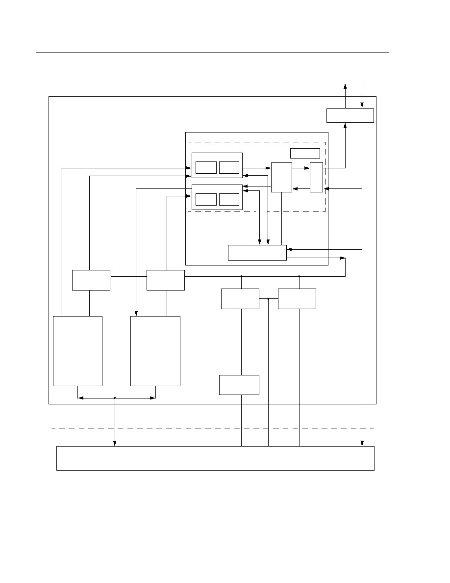
Figure 2. Demo Board
TX
FIFO
RX
FIFO
CONTROL
LOGIC
CONTROL
LOGIC
CONTROL
LOGIC
CONTROL
LOGIC
SET/CLEAR
INTERRUPT
TRANSCEIVER
HOST CPU BUS
TX/RX DATA
INTERRUPT
ADDRESS
DATA
TXD
A
T
A
RXD
A
T
A
D
ATA
ADDRESS
TX DATA
TX CONTROL
RX DATA
RX CONTROL
TEST LOGIC
REGISTERS
EVENT COUNTER
TRANSMIT
DNCM01 MACROCELL
DNCM01 KIT PART
RX CONTR
OL & ST
A
TUS
TX
CONTROL
TX
STATUS
MII
PORT
FLOW
CONTROL
RECEIVE
RX
CONTROL
RX
STATUS
TXDATA
RXDATA
TXDATA
RXDATA
DUPLEX
PAUSE
TX CONTR
OL & ST
A
TUS
5-5114 (F)

Advance Data Sheet
DNCM01
February 1997
10/100 Ethernet MAC ASIC Macrocell
Lucent Technologies Inc.
21
4
Notes:

4
Lucent Technologies Inc. reserves the right to make changes to the product(s) or information contained herein without notice. No liability is assumed as a result of their use or application. No
rights under any patent accompany the sale of any such product(s) or information.
Copyright © 1997 Lucent Technologies Inc.
All Rights Reserved
Printed in U.S.A.
February 1997
DS97-045ASIC
Printed On
Recycled Paper
For additional information, contact your Microelectronics Group Account Manager or the following:
INTERNET:
http://www.lucent.com/micro
E-MAIL:
docmaster@micro.lucent.com
U.S.A.:
Microelectronics Group, Lucent Technologies Inc., 555 Union Boulevard, Room 30L-15P-BA, Allentown, PA 18103
1-800-372-2447, FAX 610-712-4106 (In CANADA: 1-800-553-2448, FAX 610-712-4106)
ASIA PACIFIC: Microelectronics Group, Lucent Technologies Singapore Pte. Ltd., 77 Science Park Drive, #03-18 Cintech III, Singapore 118256
Tel. (65) 778 8833, FAX (65) 777 7495
JAPAN:
Microelectronics Group, Lucent Technologies Japan Ltd., 7-18, Higashi-Gotanda 2-chome, Shinagawa-ku, Tokyo 141, Japan
Tel. (81) 3 5421 1600, FAX (81) 3 5421 1700
EUROPE:
Data Requests: MICROELECTRONICS GROUP DATALINE: Tel. (44) 1189 324 299, FAX (44) 1189 328 148
Technical Inquiries: GERMANY: (49) 89 95086 0 (Munich), UNITED KINGDOM: (44) 1344 865 900 (Bracknell),
FRANCE: (33) 1 41 45 77 00 (Paris), SWEDEN: (46) 8 600 7070 (Stockholm), FINLAND: (358) 9 4354 2800 (Helsinki),
ITALY: (39) 2 6601 1800 (Milan), SPAIN: (34) 1 807 1441 (Madrid)