 | –≠–ª–µ–∫—Ç—Ä–æ–Ω–Ω—ã–π –∫–æ–º–ø–æ–Ω–µ–Ω—Ç: E2505H21 | –°–∫–∞—á–∞—Ç—å:  PDF PDF  ZIP ZIP |
Data Sheet, Rev. 1
September 2001
E2500-Type 2.5 Gbits/s Electroabsorption Modulated Isolated
Laser Module (EM-ILM) for Ultralong-Reach Applications
The E2500 EM-ILM, the newest generation of the award-
winning 266-Type EM-ILM, features an integrated modulator
and laser chip, and provides a compact, cost-effective solu-
tion for extended-reach transmissions.
Features
s
Integrated electroabsorptive modulator
s
1.5 µm wavelength
s
Characterized for 2.5 Gbits/s operation
s
Very low dispersion penalty over 600 km
s
Low modulation voltage
s
Temperature stabilized
s
Wavelengths selectable to ITU-T standards
s
Ultrastable wavelength aging performance for
DWDM systems
Applications
s
SONET/SDH extended-reach applications
s
High-capacity DWDM system applications
s
High-speed data communications
s
Digitized video
Description
The E2500-Type EM-ILM is a 1.5 µm laser with an
integrated electroabsorptive modulator packaged in
an industry-standard, 14-pin butterfly package. The
device has been designed to be used in 2.5 Gbits/s
extended-reach applications where the distances
between regenerators is in the range of 150 km--
1000 km. To boost the transmitter power high enough
to reach the receiver, the device typically is coupled
with an erbium-doped fiber amplifier (EDFA) such as
Agere Systems Inc.'s 1724 EDFA. The standard
product is specified for use up to 360 km (E2505
Series) and 600 km (E2502 Series).
The E2500 EM-ILM can replace external modulators
in many applications. The nominal input impedance
for the modulator is 50
. By integrating the
modulator with the laser chip, the device offers a
compact, cost-effective solution for extended-reach
transmission applications. It can also be specified for
WDM applications where wavelength selection is
required. Agere is providing devices compatible with
the ITU-T wavelength standards.
2
Agere Systems Inc.
Data Sheet, Rev. 1
September 2001
Isolated Laser Module (EM-ILM)
E2500-Type 2.5 Gbits/s Electroabsorption Modulated
Description
(continued)
The package also contains a thermoelectric cooler,
thermistor, back-facet monitor, and an optical isolator.
This device exhibits excellent wavelength stability,
supporting operation at 100 Gbits/s channel spacing,
assuming an end-of-life condition of < ±100 pm over 20
years for wavelength aging, with very low FIT rates.
Wavelength stabilization schemes are not required in
DWDM systems of this type, using Agere's E2500-
Type EM-ILM.
The E2500-Type EM-ILM is qualified for DWDM appli-
cations to Bellcore TA-TSY-000468.
Module Characteristics
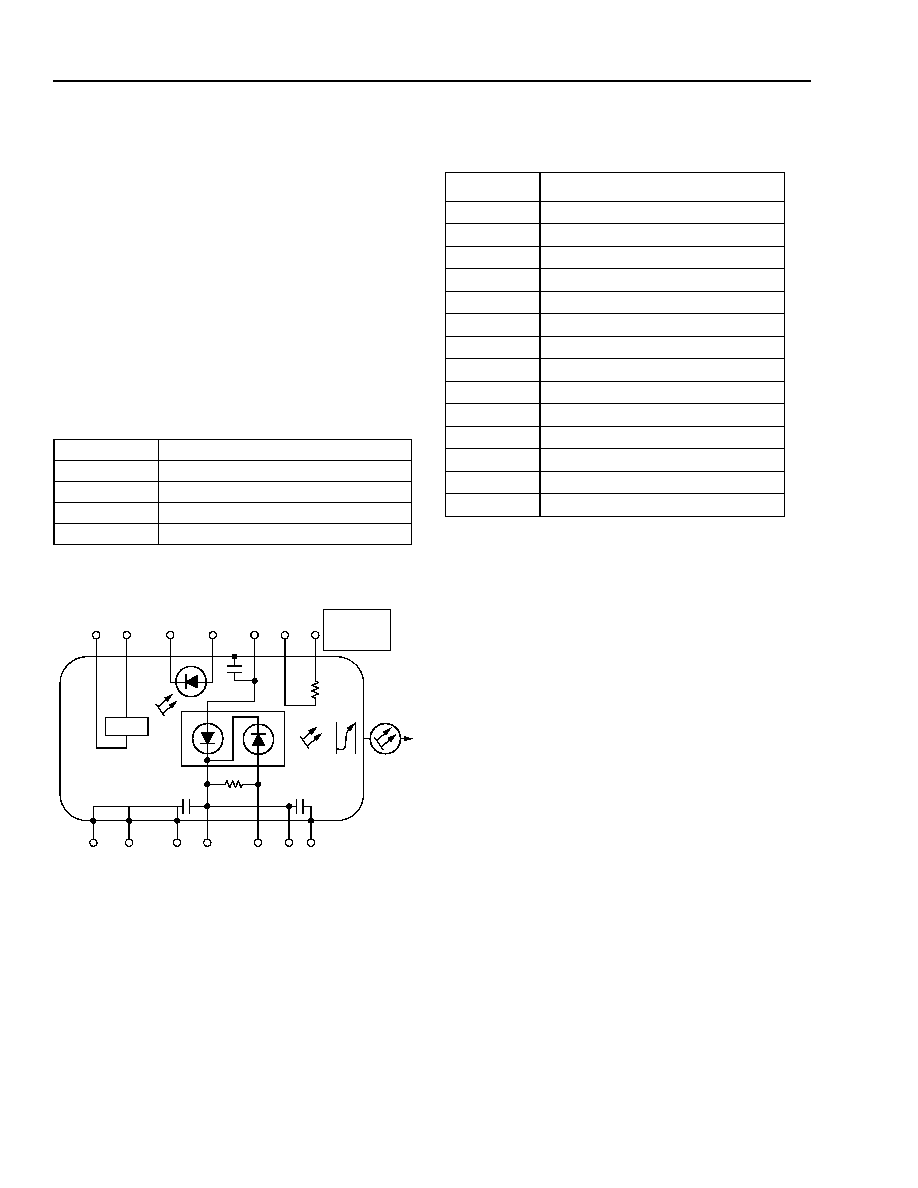
1-891a (F)
Figure 1. E2500 EM-ILM Schematic
Pin Information
Table 1. Pin Assignments
Package Type 14-pin butterfly with internal isolator
Fiber
Standard single mode
Connector
ST
Æ
RF Input
50
nominal
Bit Rate
2.5 Gbits/s
CASE OR
PACKAGE
GROUNDS
10 k
@ 25 ∞C
IS
OLA
T
OR
TEC
(
-
)
(+)
(
-
)
(+)
(+)
(
-
)
(+)
1
2
3
4
5
6
7
14
13
12
11
10
9
8
NOMINAL
IMPEDANCE
50
Pin Number
Description
1
Thermistor
2
Thermistor
3
Laser anode
4
Monitor anode
5
Monitor cathode
6
TEC (+)
7
TEC (≠)
8
Case ground
9
Case ground
10
Case ground
11
Laser modulator ground
12
Modulator anode (≠)/50
RF input
13
Laser/modulator ground
14
Case ground
Data Sheet, Rev. 1
September 2001
Isolated Laser Module (EM-ILM)
E2500-Type 2.5 Gbits/s Electroabsorption Modulated
Agere Systems Inc.
3
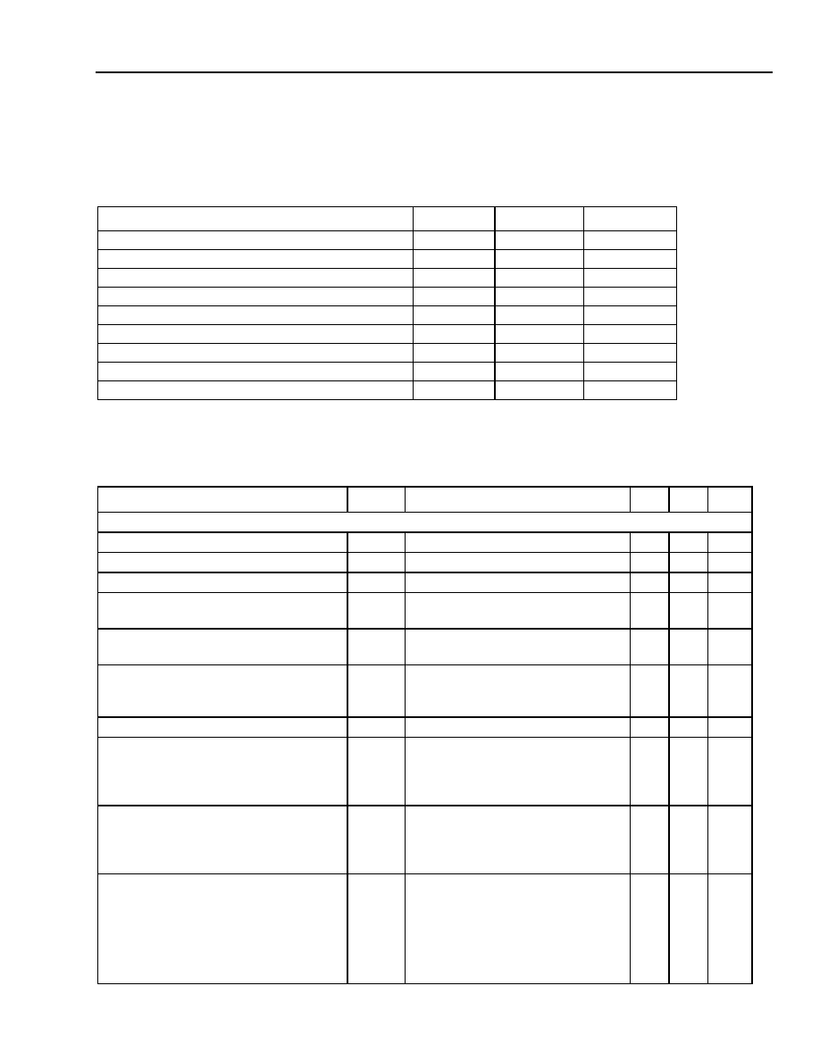
Absolute Maximum Ratings
Stresses in excess of the absolute maximum ratings can cause permanent damage to the device. These are abso-
lute stress ratings only. Functional operation of the device is not implied at these or any other conditions in excess
of those given in the operations section of the data sheet. Exposure to absolute maximum ratings for extended
periods can adversely affect device reliability.
Characteristics
Parameter
Conditions
Limit
Unit
Laser Diode Reverse Voltage
CW
2
V
Laser Diode Forward Current
CW
150
mA
Optical Output Power
CW
10
mW
Modulator Reverse Voltage
--
5
V
Modulator Forward Voltage
--
1
V
Monitor Diode Reverse Voltage
--
10
V
Monitor Diode Forward Current
--
1
mA
Storage Temperature Range
--
≠
40 to +85
∞
C
Operating Temperature Range
--
0 to 70
∞
C
Table 2. Optical and Electrical Specifications
Parameter
Symbol
Conditions
Min Max
Unit
Laser: Laser T
OP
(temperature of laser submount) = 15
∞
C to 35
∞
C, except where noted.
Threshold Current (BOL)
I
TH
T
LASER CHIP
= T
OP
5
35
mA
Forward Voltage
V
F
I
f
= I
OP
@ T
OP
--
2.0
V
Operating Current
I
OP
T
LASER CHIP
= T
OP
50
100
mA
Threshold Power
P
TH
T
LASER CHIP
= T
OP
I
f
= I
TH
, V
M
= 0 V
--
80
µ
W
Fiber Output Power (peak)
P
PK
T
LASER CHIP
= T
OP
V
M
= 0 V, I
f
= I
OP
1
--
dBm
Peak Wavelength (wavelength can be
specified to the ITU-T wavelength chan-
nels)
0
V
M
= 0 V
T
LASER CHIP
= T
OP
,
I
f
= I
OP
1530 1563
nm
Side-mode Suppression Ratio
SMSR
V
M
= 0 V, I
f
= I
OP
,T
OP
30
--
dB
Time Resolved Spectroscopy (chirp),
E2505 Series
TRS
P-P
2.5 Gbits/s
V
LOW
= ≠1.5 V to ≠3.0 V
V
HIGH
= 0 V
If = I
OP
@ T
OP
--
0.25
≈
Time Resolved Spectroscopy (chirp),
E2502 Series
TRS
P-P
2.5 Gbits/s
V
LOW
= ≠1.5 V to ≠3.0 V,
V
HIGH
= ≠0.3 V
I
f
= I
OP
@ T
OP
--
0.15
≈
Dispersion Penalty
DP
2.5 Gbits/s
360 km (E2505)
600 km (E2502)
V
LOW
= ≠1.5 V to ≠3.0 V
V
HIGH
= 0 V (E2505), ≠0.3 V (E2502)
I
F
= I
OP
@ T
OP
--
2.0
dB
Data Sheet, Rev. 1
September 2001
Isolated Laser Module (EM-ILM)
E2500-Type 2.5 Gbits/s Electroabsorption Modulated
4
Agere Systems Inc.
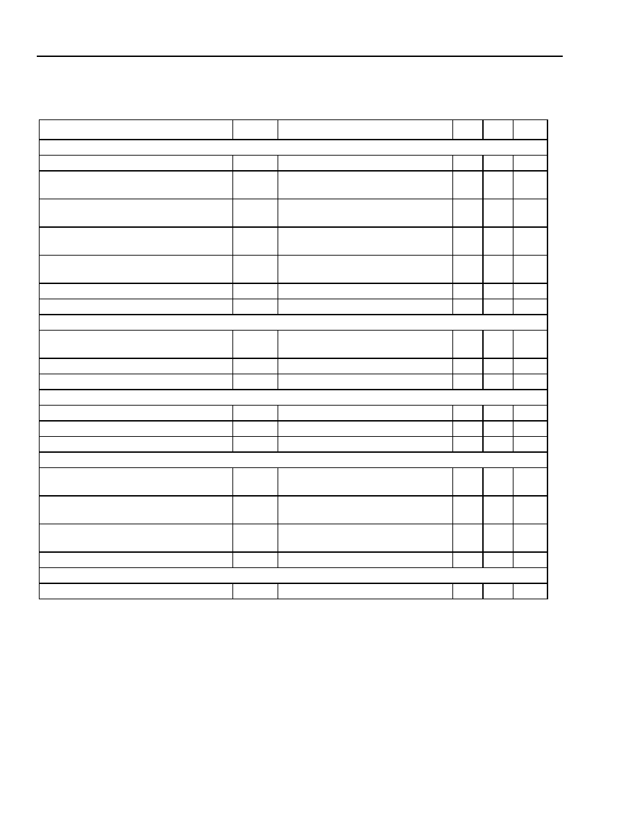
Characteristics
(continued)
* Operation at a DT of 70 ∞C ≠ TSET is guaranteed, where TSET is the laser temperature required to achieve the required ITU wavelength,
over life, in a DWDM system (TSET range is 15 ∞C to 35 ∞C). In a non-WDM application, TSET is 25 ∞C.
Modulator
Extinction Ratio
E
RRF
V
M
= 0 V to ≠3.0 V, 2.5 Gbits/s
10
--
dB
RF Return Loss (0 GHz to 2 GHz)
S
11
V
M
= ≠V
PP
/2
I
f
= I
OP
10
--
dB
RF Return Loss (2 GHz to 3 GHz)
S
11
V
M
= ≠V
PP
/2
I
f
= I
OP
7
--
dB
RF Return Loss (3 GHz to 5 GHz)
S
11
V
M
= ≠V
PP
/2
I
f
= I
OP
3
--
dB
≠3 dB Bandwidth
BW
V
M
= ≠V
PP
/2
I
f
= I
OP
3.5
--
GHz
Modulator Current @
V
M
= 0 V,
I
f
= 50 mA
--
--
--
15
mA
Rise/Fall Time (20% to 80%)
t
R
/
t
F
--
--
125
ps
Monitor Diode
Monitor Current
I
BD
T
LASER CHIP
= T
OP
V
BD
= 5 V, I
f
= I
OP
40 1100
µ
A
Dark Current
I
D
T
LASER CHIP
= T
OP
, V
BD
= ≠5 V
--
0.1
µ
A
Capacitance
C
V
BD
= 5 V, f = 1 MHz
--
25
pF
Thermistor
Resistance
R
THERM
T = 25
∞
C
9.5
10.5
k
Thermistor Current
I
TC
--
10
100
µ
A
Thermistor B Constant
B
--
3700 4100
--
Thermoelectric Cooler
TEC Current
I
TEC
T
LASER CHIP
= 15
∞
C
T
CASE
= 70
∞
C
--
1.3
A
TEC Voltage
V
TEC
T
LASER CHIP
= 15
∞
C
T
CASE
= 70
∞
C
--
2.6
V
TEC Power
P
TEC
T
LASER CHIP
= 15
∞
C
T
CASE
= 70
∞
C
--
3.0
W
TEC Capacity
T
T
CASE
= 70
∞
C
*
--
∞
C
Laser Module
Optical Isolation
--
T
CASE
= 0
∞
C to 65
∞
C
30
--
dB
Table 2. Optical and Electrical Specifications (continued)
Parameter
Symbol
Conditions
Min Max
Unit
Data Sheet, Rev. 1
September 2001
Isolated Laser Module (EM-ILM)
E2500-Type 2.5 Gbits/s Electroabsorption Modulated
Agere Systems Inc.
5
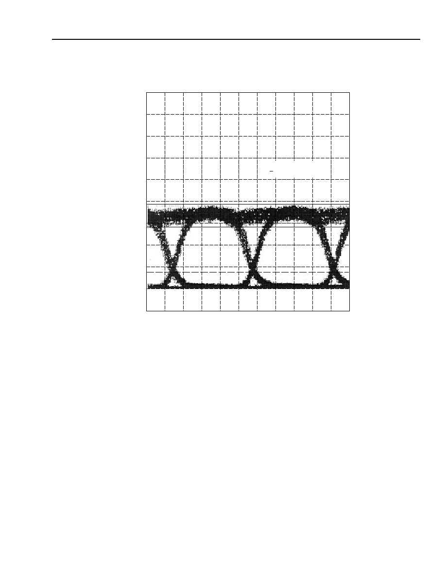
Characteristics
(continued)
1-500(C).d
Figure 2. Typical Eye Pattern at 2.5 Gbits/s
184.5 mV
I = 50
V = ≠1.04 + 2.08 pp
P= ≠0.5 dBm
≠15.5 mV
20 mV
/div
91.65 ns
100 ps/div
92.65 ns