 | –≠–ª–µ–∫—Ç—Ä–æ–Ω–Ω—ã–π –∫–æ–º–ø–æ–Ω–µ–Ω—Ç: NPASI | –°–∫–∞—á–∞—Ç—å:  PDF PDF  ZIP ZIP |

Product Brief
June 2001
PayloadPlusTM Agere System Interface
Introduction
The Agere Systems PayloadPlus architecture
provides a unique hardware and software
combination that delivers high-speed processing
for multiple communication protocols with full
programmability. This combination gives you the
programmability of traditional RISC processors
with the speed that, until now, only ASICs could
deliver.
The Agere Systems PayloadPlus product family
represents a technology revolution for the
construction of intelligent communication
equipment with Layer 3 or above processing
capabilities. Agere Systems products focus on the
wire-speed datapath functions and work in
conjunction with physical interface devices, low-
speed microprocessor, and backplane fabric
offerings to provide a complete solution for
networking and communication applications. The
PayloadPlus processor family includes the Fast
Pattern Processor (FPP), Routing Switch
Processor (RSP), and the Agere System Interface
(ASI).
The Agere Systems PayloadPlus Processors are
designed to handle wire-speed data streams at up
to OC-48c rates. Each chip provides a
complementary function: the FPP for high-speed
classification, the RSP for processing and routing
traffic, and the ASI to provide policing, manage
state information, and provide a PCI connection to
a host processor.
The FPP accepts a data stream of protocol data
units (PDUs) from an industry-standard POS-
PHY/UTOPIA Level 3 interface. The PDUs are
analyzed and classified, and the FPP outputs the
packets and conclusions to the RSP on a POS-
PHY Level 3 interface.
Agere System Interface
The ASI seamlessly integrates the FPP and RSP
with the host processor. The wire-speed data
stream operations are performed by the FPP,
RSP, and ASI. The host processor is used
exclusively for slow path processing--it is not
used for pattern recognition, classification,
queuing, or traffic management operations.
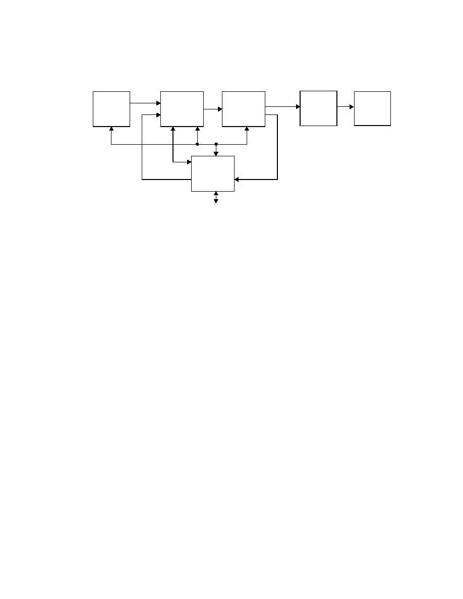
A typical system using the ASI, the FPP, and the
RSP is shown in the block diagram in this
document.
Features and Benefits of the ASI
s
An industry-standard interface to the FPP and
RSP for a host microprocessor that allows:
-- Centralized initialization and configuration
of the FPP, RSP, and physical interfaces.
-- Routing and VPI/VCI table updates to the
FPP.
-- Queue processing updates to the RSP.
-- Implementation of routing and
management protocols.
-- Exception handling.
s
High-speed, flow-oriented state maintenance
for the FPP, including:
-- RMON statistics gathering.
-- Packet sequence checking.
-- Packet time stamping.
-- ATM and Frame Relay policing at up to
OC-48c rates.
-- An 8-bit POS/PHY interface to send
packets to the FPP and receive packets
from the RSP.

Product Brief
NPASI
June 2001
Agere System Interface
2
Applications
You can use the ASI in the following applications:
s
Communicate with the host control processor using a
Peripheral Component Interconnect (PCI) bus.
s
Send and receive protocol data units (PDUs) using an 8-bit
POS/PHY interface.
s
Service FPP function calls using an ALU, SRAM, and a
high-speed 32-bit Functional Bus Interface (FBI).
s
Maintain state information on PDUs, flows, or connections
using optional SRAM.
s
Police ATM and Frame Relay connections.
s
Configure up to eight devices using an 8-bit Configuration
Bus.
ASI Interfaces
The ASI supports the following interfaces:
s
PCI Interface--The ASI has a 64-bit, 66-MHz PCI interface
that is a full master/slave implementation with DMA and
interrupt support.
s
POS/PHY Interface--The ASI's 8-bit POS/PHY interfaces
operate at up to 133 MHz and allow the host processor to
receive PDUs from the RSP and send PDUs to the FPP.
s
Functional Bus Interface (FBI)--The ASI's 32-bit
Functional Bus Interface extends the capabilities of the
FPP by allowing the FPP to make function calls that are
executed by the ASI.
s
SSRAM Memory Interfaces--Two industry-standard 32-bit
memory interfaces.
s
Configuration Bus Interface--The ASI's 8-bit Configuration
Bus allows the host processor to configure the FPP and
RSP, and up to six additional devices.
FPP Function Calls to the ASI
The FPP is programmed using the Functional Programming
Language (FPL). FPL code can invoke functions that are
executed on external hardware, extending the capabilities of
the FPP. The ASI contains an ALU and an SSRAM interface
state buffer used to implement functions that are invoked by
FPL code. These functions include:
s
Policing ATM and Frame Relay traffic.
s
RMON operations.
s
Time-stamping PDUs.
s
Capturing and maintaining statistics.
s
PDU sequence checking for Frame Relay reassembly.
ASI Policing Capabilities
The ASI supports high-speed policing of ATM and Frame
Relay traffic. It can use one of several leaky-bucket
configurations. The default configuration uses the GCRA
algorithm defined by the ATM Traffic Management
Specification, version 4.0.
When the FPL program calls the policing function for a PDU,
the ASI checks for compliance and returns flags that indicate
whether the cell or frame is compliant. The FPL program then
determines the action to take. For example, the FPL program
could simply flag noncompliant PDUs, or it could discard
them.
The ASI supports policing at rates up to OC-48c.
ASI
RSP
FPP
Physical
Interface
8-b it P O S -P H Y
8-bit PO S-PH Y
P C I to H ost C P U
F B I
C onfiguration B us
P O S -P H Y
P O S -P H Y
U TO P IA
U TO P IA
System O verview
Fabric
Fabric
Interface
Controller

Product Brief
NPASI
June 2001
Agere Systems Interface
3
ASI Configuration Capabilities
The ASI is designed to allow the host processor to configure
up to eight devices using the Configuration Bus. The ASI
Configuration Bus Interface is compatible with both the Intel
and Motorola bus formats, allowing configuration of third
party devices such as framers and physical interfaces.
The ASI Configuration Bus is used to:
s
Initialize and configure the FPP and RSP.
s
Load the program code for the FPP and RSP.
s
Load the dynamic updates to the FPP tables and the RSP
queues.
s
Configure third party external framers and physical
interfaces.
How the ASI Works
The ASI performs multiple tasks for the FPP, RSP, and host
processor. It is designed to perform these functions and
support policing at wire-speed data stream rates of up to OC-
48c. To meet these requirements, the ASI employs the
following components:
s
A PCI interface for communicating with the host processor.
s
A high-speed 32-bit Functional Bus Interface (FBI) for
servicing FPP function calls.
s
Two ALUs for processing FPP external function requests:
one for maintaining state and statistics, and another for
policing.
s
Two SSRAM interfaces, to allow memory access for
different tasks without contention.
s
Two 8-bit POS-PHY (Level 3) interfaces, one for receiving
PDUs from the RSP, an the other for sending PDUs to the
FPP. Because these are standard interfaces, they can be
connected to other devices.
s
An 8-bit configuration bus for configuring up to eight
devices, including the FPP and the RSP.
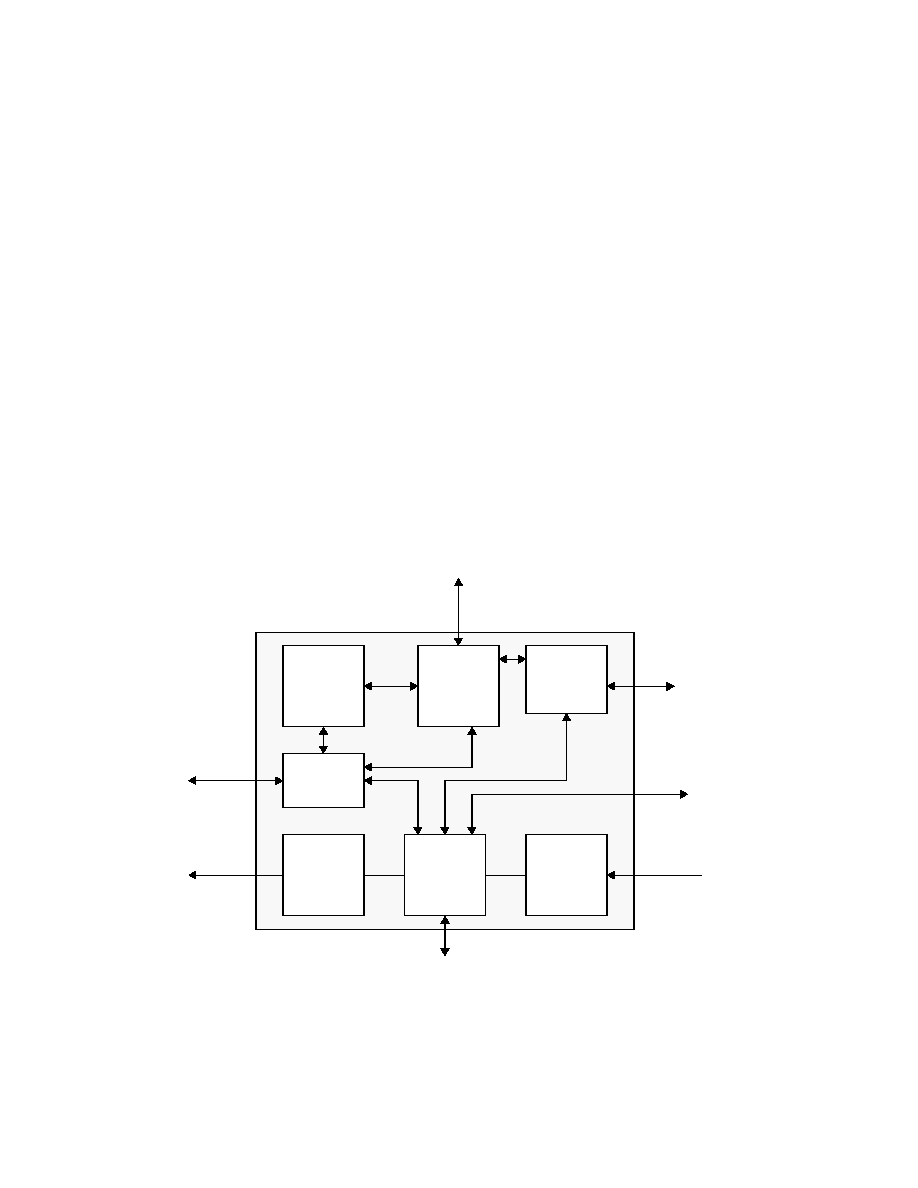
ASI Internal Architecture
The block diagram that follows shows the internal
architecture of the ASI.
ALU
PDU Data
Transmit
Interface
PCI
Interface
PDU Data
Receive
Interface
FBI
Control
Logic
SSRAM
Interface
Policing
Compute
Engine
SSRAM
Interface
ASI
FBI
POS-PHY
POS-PHY
From RSP
To FPP
Configuration
Bus
PCI to Host Processor
Policing
SSRAM
State
SSRAM
Agere System Interface Internal Block Diagram

Product Brief
NPASI
June 2001
Agere System Interface
4
ASI Operation
The Agere System Interface supports the transfer of
management frames and statistics to a PCI host application.
PDUs received on the ASI's 8-bit POS-PHY (Level 3)
interface are transferred to host memory using the ASI's
DMA master capability. PDUs can also be generated by the
host processor and sent out on the 8-bit POS-PHY (Level 3)
interface.
Additionally, the ASI maintains a large management
information database for state and statistics gathering. These
statistics are updated by FPL function calls invoked by the
FPP and sent across the Functional Bus Interface. The
interface to the database provides several ALU operations for
modifying and comparing values in the database. The ASI
can return values to the calling FPL function.
A second database can be maintained by the ASI to
determine traffic contract compliance using one of several
versions of the dual leaky bucket algorithm. The algorithm is
implemented using a programmable compute engine. The
FPP can make a function call to the ASI to invoke the policing
algorithm. The algorithm called with the function returns a
pass/fail value indicating whether or not the cell or frame is
compliant.
The FPP and RSP configuration is handled by the ASI's
Configuration Bus. This configuration bus is compatible with
both Intel and Motorola bus formats, allowing it to be used to
set up external PHY and framer devices as well.
Policing/Conformance Checking
The ASI performs conformance checking or policing for up to
64k connections, flows, or aggregates for up to OC-48 rates.
No scheduling or traffic shaping is done, only the marking of
cells or frames that are noncompliant. ATM and Frame Relay
conformance checking may be done using one of several
variations of the GCRA (leaky-bucket) algorithm. Each of
these variations is a subset of the dual-leaky-bucket
algorithm. The ATM Forum TM 4.0 specification specifies
conformance definitions as combinations of leaky-bucket
configurations. In the case of a dual leaky bucket, the ASI will
indicate whether cells or frames are compliant or
noncompliant and from which bucket the nonconformance
was derived.
Examples of leaky-bucket paradigms follow, although other
combinations are possible. Different connections may use
different algorithms, and each connection can have its own
GCRA parameters. The only restriction is that the arrival
times (t
a
(i)) must be measured with the same granularity. For
example, if both ATM and Frame Relay connections are
being policed, the timestamp counter must be set to measure
the smaller of the ATM cell rate, or the byte time of the FR
connection.
Single Leaky Bucket
The simplest leaky-bucket algorithm is the single leaky
bucket. This algorithm uses two parameters: the Increment (I)
and the Limit (L). The Increment value corresponds to the
leak rate of the bucket, and the Limit corresponds to the
bucket depth.
Dual Leaky Bucket
The dual leaky-bucket algorithm applies two leaky buckets to
a single connection. The Increment and Limit parameters for
each bucket can be assigned based on several parameters,
depending on the application.
For example, in a typical application one bucket leaks at the
sustained cell rate (SCR) and the other leaks at the peak cell
rate (PCR). ATM cells that do not conform can be tagged by
setting the Cell Loss Priority bit equal to one.
CLP-based Buckets
The ATM Forum TM 4.0 specification defines variations on
the dual leaky-bucket algorithm, including using the cell loss
priority (CLP) bit as a policing parameter. The dual leaky
bucket algorithm can be used to police cells differently, based
on the cell's CLP bit value.
This CLP-based, dual leaky-bucket algorithm adds both
CLP=0 and CLP=1 cells to both buckets. Discarded cells are
marked as SCR or PCR discards, and any actions taken are
determined by the FPP and RSP programming.Policing ATM
and Frame Relay traffic.
The connection policing rates and the actions to be taken for
noncompliance are programmable.
For each connection you can select:
s
The algorithm used, such as single leaky bucket or dual
leaky bucket.
s
The negotiated ATM cell rates, including peak cell rate
(PCR), and sustainable cell rate (SCR).
s
The ATM tolerance parameters, including maximum burst
size (MBS), burst tolerance (BT), and cell delay variation
tolerance (CDVT).
s
The Frame Relay Service supported access line rates,
such as committed information rate (CIR).
The ASI maintains the policing parameters--and policing
status--for each connection or set of connections defined by
the FPP. The FPP is responsible for calling the policing

Product Brief
NPASI
June 2001
Agere Systems Interface
5
function in the ASI for PDUs, and sending the policing results
to the RSP. The RSP programmable queues determine the
action to take based on the policing conclusions.
CLP=0
CLP=1
SCR
PCR
Tag B2
Tag B1
Leaky Bucket Algorithms

Agere Systems, Inc. reserves the right to make changes to the product(s) or information contained herein without notice. No liability is assumed as a result of their use or application. PayloadPlus
is a trademark of Agere Systems, Inc.
Copyright © 2001 Agere Systems, Inc.
All Rights Reserved
Printed in U.S.A.
6/1/01
PB01-131NP
Printed On
Recycled Paper
For additional information, contact your Agere Systems Account Manager or the following:
INTERNET:
http://www.agere.com
E-MAIL:
docmaster@micro.lucent.com
N. AMERICA:
Agere Systems, Inc., 555 Union Boulevard, Room 30L-15P-BA, Allentown, PA 18103
1-800-372-2447, FAX 610-712-4106 (In CANADA: 1-800-553-2448, FAX 610-712-4106)
ASIA PACIFIC: Agere Systems, Inc., Singapore Pte. Ltd., 77 Science Park Drive, #03-18 Cintech III, Singapore 118256
Tel. (65) 778 8833, FAX (65) 777 7495
CHINA:
Agere Systems, Inc. (China) Co., Ltd., A-F2, 23/F, Zao Fong Universe Building, 1800 Zhong Shan Xi Road, Shanghai 200233 P. R. China Tel.
(86) 21 6440 0468, ext. 316, FAX (86) 21 6440 0652
JAPAN:
Agere Systems, Inc. Japan Ltd., 7-18, Higashi-Gotanda 2-chome, Shinagawa-ku, Tokyo 141, Japan
Tel. (81) 3 5421 1600, FAX (81) 3 5421 1700
EUROPE:
Data Requests: Agere Systems, Inc. DATALINE: Tel. (44) 7000 582 368, FAX (44) 1189 328 148
Technical Inquiries: GERMANY: (49) 89 95086 0 (Munich), UNITED KINGDOM: (44) 1344 865 900 (Ascot),
FRANCE: (33) 1 40 83 68 00 (Paris), SWEDEN: (46) 8 594 607 00 (Stockholm), FINLAND: (358) 9 4354 2800 (Helsinki),
ITALY: (39) 02 6608131 (Milan), SPAIN: (34) 1 807 1441 (Madrid)


