Product Description, Revision 4
April 29, 2005
TFRA84J13 Ultraframer
DS3/E3/DS2/E2/DS1/E1/DS0
1 Introduction
The documentation package for the TFRA84J13 Ultraframer DS3/E3/DS2/E2/DS1/E1/DS0 chip consists of the following
documents:
The UltramapperTM Family Register Description and the Ultramapper Family System Design Guide. These documents
are available on a password protected website.
The Ultraframer Product Description (this document) and the Ultraframer Hardware Design Guide. These documents
are available on the public website shown below.
To contact Agere, please see the last page of this document.
To access related documents, including the documents mentioned above, please go to the following public website, or
contact your Agere representative:
http://www.agere.com/telecom/mappers_muxes.html
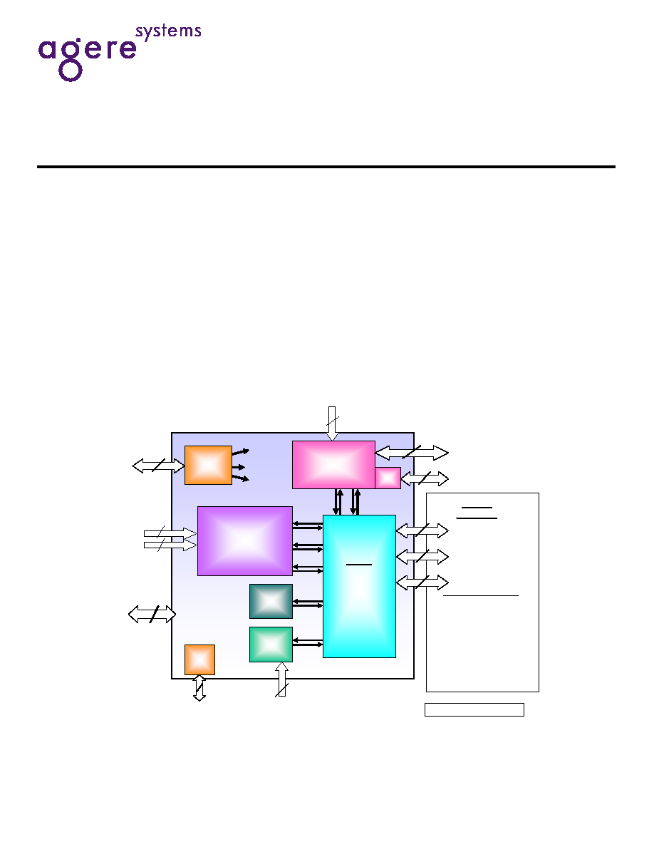
Figure 1-1. Ultraframer Block Diagram and High-Level Interface Definition
System
Interfaces
Switching modes:
8PSB (x16)- x84/X63 DS1/J1/E1
x2016 DS0/E0
4CHI (x18) - x2016 DS0/E0
Transport modes:
4DS1/J1/E1 (x86) -x84/x63 + prot
.
4DS2/E2 (X86) � x63/x36 + prot.
(x3) DS3/E3
(x3) NSMI
(framer)
Shared Low Speed I/O
(x3)
M13/
E13
MUX
FRM
x84/x63
DS1/J1/E1
MRXC
DS1/J1/E1
DS2/
E2
DS3/
E3
TPG/TPM
x84/x63
DS1/E1
DJA
24
MPU IF
5
CHI/PSB
Rx/Tx Clocks and Sync
5
5
JTAG
JTAG IF
FRM PLL IF
21
380
DS1XCLK,
E1XCLK
CG
MPU
48
Miscellaneous
13
2
Power and GND pins not shown
10/10/02
E2AISCLK/
DS2AISCLK
1
1
THSC
Framer CLK
2
System
Interfaces
Switching modes:
8PSB (x16)- x84/X63 DS1/J1/E1
x2016 DS0/E0
4CHI (x18) - x2016 DS0/E0
Transport modes:
4DS1/J1/E1 (x86) -x84/x63 + prot
.
4DS2/E2 (X86) � x63/x36 + prot.
(x3) DS3/E3
(x3) NSMI
(framer)
Shared Low Speed I/O
(x3)
M13/
E13
MUX
FRM
x84/x63
DS1/J1/E1
MRXC
DS1/J1/E1
DS2/
E2
DS3/
E3
TPG/TPM
x84/x63
DS1/E1
DJA
24
24
MPU IF
5
5
CHI/PSB
Rx/Tx Clocks and Sync
5
5
5
5
JTAG
JTAG IF
FRM PLL IF
21
21
380
380
DS1XCLK,
E1XCLK
CG
MPU
48
48
Miscellaneous
13
2
Power and GND pins not shown
10/10/02
E2AISCLK/
DS2AISCLK
1
1
THSC
Framer CLK
2

TFRA84J13 Ultraframer
Product Description, Revision 4
DS3/E3/DS2/E2/DS1/E1/DS0
April 29, 2005
2
2
Agere Systems Inc..
1 Introduction .........................................................................................................................................................................1
2 Features .............................................................................................................................................................................3
2.1 Test Pattern Generator/Monitor (TPG/TPM) (x1) ........................................................................................................3
2.2 M13/E13 MUX (x3) ......................................................................................................................................................3
2.2.1 M13 ....................................................................................................................................................................3
2.2.2 E13 .....................................................................................................................................................................3
2.3 DS1/J1/E1 Framing (FRM) (3x28/21) ..........................................................................................................................4
2.4 DS3/E3/DS2/E2/DS1/E1 Multirate Cross Connect (MRXC) (x1) .................................................................................4
2.5 DS1/E1 Digital Jitter Attenuation (DJA) (3x28/21) .......................................................................................................5
2.6 Microprocessor Unit (MPU) (x1) ..................................................................................................................................5
2.7 JTAG ...........................................................................................................................................................................5
3 Overview .............................................................................................................................................................................6
4 Application Diagrams ..........................................................................................................................................................7
4.1 DS3/E3 to/from DS1/E1 Application ............................................................................................................................7
4.2 DS3/E3 to/from DS0/E0 Application ............................................................................................................................8
4.3 DS1/E1 to/from DS0/E0 Application ............................................................................................................................9
5 Block Description ..............................................................................................................................................................10
5.1 M13/E13 Multiplexer (M13/E13 MUX) .......................................................................................................................10
5.1.1 M13 MUX .........................................................................................................................................................10
5.1.1.1 Receive Direction ..................................................................................................................................10
5.1.1.2 Transmit Direction .................................................................................................................................10
5.1.2 E13 MUX ..........................................................................................................................................................10
5.2 Multirate Cross Connect (MRXC) ..............................................................................................................................11
5.3 DS1 Digital Jitter Attenuator (DS1/E1 DJA) ...............................................................................................................11
5.4 Test Pattern Generator/Monitor (TPG/TPM) .............................................................................................................11
5.5 Clock Generator (CG) ................................................................................................................................................12
5.6 Framer (FRM) ............................................................................................................................................................12
5.6.1 Line Decoder/Encoder .....................................................................................................................................12
5.6.2 Receive Frame Aligner/Transmit Frame Formatter ..........................................................................................12
5.6.3 Receive Performance Monitor ..........................................................................................................................12
5.6.4 Signaling Processor .........................................................................................................................................13
5.6.5 Facility Data Link (FDL) Processor ..................................................................................................................13
5.6.6 HDLC Unit ........................................................................................................................................................13
6 Glossary ...........................................................................................................................................................................14

3
3
Agere Systems Inc.
TFRA84J13 Ultraframer
Product Description, Revision 4
DS3/E3/DS2/E2/DS1/E1/DS0
April 29, 2005
2 Features
Versatile IC supports solutions for DS3/E3, DS2/E2,
DS1/J1/E1, and DS0/J0/E0 applications.
Terminates up to 84 DS1/J1 or 63 E1 framed or
unframed signals. All popular framing formats are sup-
ported.
Terminates up to three DS3/E3, 21 DS2, or 12 E2
signals.
3.3 V I/O, 1.5 V CORE, low power (<2.5 W) and �40
�
C
to +85
�
C temperature range allows for uncontrolled or
convection cooled environments.
Loopbacks, manual error insertion, internal pattern
generator/monitor, and internal cross connects simplify
debugging and diagnostics.
Standard 909-pin ball grid array (PBGA) with 35 mm
square with 1.0 mm square ball pitch.
Complies with all appropriate Telcordia
�
, ITU, ANSI
�
,
ETSI, and Japanese TTC standards as noted.
2.1 Test Pattern Generator/Monitor (TPG/TPM)
(x1)
Configurable test pattern generator: DS1, E1, and DS2
formats.
Provisionable test pattern data from the following
options: quasirandom signal source (QRSS), pseudoran-
dom bit stream length of 2
15
�1 (PRBS15), PRBS20,
PRBS23, alternating 1 and 0 (ALT_01), ALL_ONES, user
pattern (16 bits, repeating).
The DS1 and E1 test patterns can be transmitted either
unframed or as the payload of a framed signal as defined
in ITU-T.
Under register control, single bit or framing (DS1/E1
only) errors can be injected into any test pattern.
Any sink or receiving channel can be replaced by a test
pattern monitor, which can detect and count bit errors or
misconfigurations, and/or detect idle conditions or AIS.
Datalink (DS1-ESF DL) and SSM (E1 multiframe Sa)
fields read/writable.
Supports all Ultraframer modes of operation.
Complies with T1.107, T1.231, T1.403, G.703, G.704,
and O.150.
2.2 M13/E13 MUX (x3)
2.2.1 M13
Configurable multiplexer/demultiplexer for 28 DS1 sig-
nals, 21 E1 signals, or seven DS2 signals to/from a DS3
signal.
Operates in either M23 or C-bit parity mode.
Provisionable time-slot selection for DS1, E1, and DS2
insertion or drop.
Full alarm monitoring and generation (LOS, BPV, EXZ,
OOF, SEF, AIS, RAI, FEAC, P-bit and C-bit parity errors,
and FEBE).
DS3 forced loopback and DS2, DS1, and E1 forced loop-
back and loopback request generation.
Complies with T1.102, T1.107, T1.231, T1.403, T1.404,
GR 499, G.747, and G.775.
2.2.2 E13
Configurable multiplexer/demultiplexer for up to 16 E1
signals or four E2 signals, to/from an E3 signal.
Independently configurable four E12 multiplexer/demulti-
plexers for up to 16 E1 signals to/from four E2 signals.
Provisionable time-slot selection for E1 and E2 insertion
or drop via the multirate cross connect functional block.
E12 and E23 multiplexers capable of generating alarm
indication signal (AIS) and remote alarm indicator (RAI)
signals.
Configurable HDB3 encoder/decoder for E3 output/input.
E1 and E2 transmit path monitors that detect loss-of-
clock (LOC) and AIS.
E2 receive path monitor that detects LOC, AIS, and RAI.
E3 receive monitor that detects loss-of-signal (LOS),
LOC, bipolar violation (BPV), AIS, and RAI.
E3 and E2 loopback modes.
Complies with ITU G.703, G.742, G.751, and G.775.

Agere Systems Inc.
4
Product Description, Revision 4
TFRA84J13 Ultraframer
April 29, 2005
DS3/E3/DS2/E2/DS1/E1/DS0
2.3 DS1/J1/E1 Framing (FRM) (3x28/21)
28/21 DS1/J1/E1 channels.
Line coding: B8ZS, HDB3, ZCS, AMI.
Note: Available only on 18 channels out of 84/63.
DS1 framing modes: ESF, D4, SLC
�
-96, T1 DM DDS,
and SF (F
t
only).
E1 framing modes: G.704 basic and CRC-4 multiframe
consistent with G.706.
J1 framing modes: JESF (Japan).
Supports DS1 and E1 unframed and transparent trans-
mission format.
DS1 signaling modes: transparent; register and system
access for ESF 2-state, 4-state, and 16-state; D4 2-state,
4-state, and 16-state; SLC-96 2-state, 4-state, and
16-state; J-ESF handling groups maintenance and
signaling; VT 1.5 SPE 2-state, 4-state, 16-state.
E1 signaling modes: transparent; register and system
access for entire TS16 multiframe structure as per ITU
G.732.
Signaling debounce and change of state interrupt.
V5.2 Sa7 processing.
Alarm reporting and performance monitoring per AT&T
�
,
ANSI, ITU-T, and ETSI standards.
Facility data link features:
-- HDLC or transparent access for either ESF or
DDS + FDL frame formats.
-- Register/stack access for SLC-96 transmit and receive
data.
-- Extended superframe (ESF): automatic transmission
of the ESF performance report messages (PRM).
Automatic transmission of the ANSI T1.403 ESF per-
formance report messages. Automatic detection and
transmission of the ANSI T1.403 ESF FDL bit-oriented
codes.
-- Register/stack access for all CEPT Sa bits transmit
and receive data.
HDLC features:
-- HDLC or transparent mode.
-- Programmable logical channel assignment: any time
slot, any bit for ISDN D channel, also inserts/extracts
C-channels for V5.1, V5.2 interfaces.
-- 64 logical channels in both transmit and receive
direction (any framing format).
-- Maximum channel data rate is 64 kbits/s.
-- Minimum channel data rate is 4 kbits/s (DS1/FDL or
E1 Sa bit).
-- 128-byte FIFO per channel in both transmit and
receive directions.
-- Tx to Rx loopback supported.
System interfaces:
-- Concentration highway interface:
Single clock and frame synchronizing signals;
programmable clock and data rates at 8.192 MHz
and 16.384 MHz; programmable clock edges and
bit/byte offsets.
-- Parallel system bus interface at 19.44 MHz for data
and signaling: single clock and frame synchronizing
signals.
-- Network serial multiplexed interface (NSMI) minimal
pin count serial interface at 51.84 MHz optimized for
data and IMA applications.
2.4 DS3/E3/DS2/E2/DS1/E1 Multirate Cross Con-
nect (MRXC) (x1)
Configurable cross point interconnect for up to 84/63
DS1/E1 signals to/from the FRM, VTMPR, M13/E13,
TPG/TPM, DS1/E1 DJA, and 86 external I/O pins. Also
supports 21/12 DS2/E2 to/from external I/O pins from/to
the M13/E13 functional block.
Connects three DS3/E3 signals from the external pins to
the M13/E13 MUX.
Provides grooming capability for up to 168 (84 receive
plus 84 transmit) DS1/E1 connections between the FRM,
M13/E13, DS1/E1 DJA, and 86 bidirectional sets of pins.
This allows for cross connect grooming of any block sig-
nal port n to any other signal port m on a different block
or output pin, or on the same block in the case of a
groomed loopback.
Multicast operation (one to many) is supported for 168
sources and destinations.
Any mix of DS2, E2, DS3, or E3 signals can interconnect.
Multirate cross connect allows 16 x 3 E1 signals to/from
E13 modules from/to the framer, TPG/TPM, and external
pins.
There are 4 x 3 E2 signals to/from E13 from/to external
pins.
There are three E3 signals from/to the E13 functional
block to/from external pins.
Jitter attenuation can also be inserted in-line on any
channel. (Note that cascading of jitter attenuators is not
allowed.)
Standard network loopback or straight-away facility test-
ing is supported for DS1/E1 and DS3/E3. A DS1/E1 test-
pattern generator capable of injecting idle standards-
based, pseudorandom bit sequence test patterns, or AIS
(blue) alarm can replace any source or transmitter. A
test-pattern monitor that can detect/count bit errors in a
pseudorandom test sequence, or loss of frame or syn-
chronization, can replace any sink or receiver.

5
5
Agere Systems Inc.
TFRA84J13 Ultraframer
Product Description, Revision 4
DS3/E3/DS2/E2/DS1/E1/DS0
April 29, 2005
One to any number of loopbacks are supported for up to
84/63 channels in DS1/E1 channels from the M13/E13
and framer functional blocks. One-to-one loopback is
supported in all DS1/E1 channels. One-to-one loopback
is supported for DS3/E3 channels from the M13/E13
functional blocks.
Loopbacks can be configured to sectionalize a circuit for
identifying faults or misconfiguration during out of service
maintenance.
Fast alarm channels are supported for E13 and M13 to
framer interconnects for alarm indication signal (AIS or
blue alarm). This feature reduces the propagation delay
of the alarms by eliminating multiple integration of alarm
conditions.
Supports framer-only, transport (framer LIU, M13, and
E13), and switching (CHI and PSB) modes of operation.
2.5 DS1/E1 Digital Jitter Attenuation (DJA)
(3x28/21)
The PLL bandwidth, damping factor, and sampling rates
are programmable.
Configurable to meet jitter and MTIE requirements.
Supports one DJA per each DS1/E1. (Note that the DJA
may not be cascaded.) There are 28/21 DJA channels
per block.
2.6 Microprocessor Unit (MPU) (x1)
21-bit address/16-bit data bus microprocessor interface
(little-endian).
Synchronous (16 MHz to 66 MHz)/asynchronous micro-
processor interface modes.
Microprocessor data bus parity monitoring.
Summary of two level priority interrupts from the E13
block (maskable).
Global configuration of network performance monitoring
counters operation.
Global software resets.
Global enabling and powerdown of major functional
blocks.
Registers provisionable for clear on read/clear on write.
Compatible with most industry-standard processors.
2.7 JTAG
IEEE
�
1149.1 JTAG boundary scan.

TFRA84J13 Ultraframer
Product Description, Revision 4
DS3/E3/DS2/E2/DS1/E1/DS0
April 29, 2005
6
6
Agere Systems Inc..
3 Overview
The Ultraframer provides a versatile interface for DS1/J1/E1, DS3/E3, DS2/E2, and DS0/J0/E0 applications. The
Ultraframer device integrates M13/E13 multiplex/demultiplex functions and the primary rate framing function.
Each interface consists of a fully integrated, full featured, primary rate framer with HDLC formatter for facility data link
access. It also provides alarm reporting and bidirectional performance monitoring. The TFRA84J13 provides glueless inter-
connection to analog line interface units and time-slot interchangers.
Product Description, Revision 4
TFRA84J13 Ultraframer
April 29, 2005
DS3/E3/DS2/E2/DS1/E1/DS0
Agere Systems Inc.
7
4 Application Diagrams
This section shows several typical Ultraframer applications. Figure 9-1 through Figure 9-3 depict system-level diagrams.
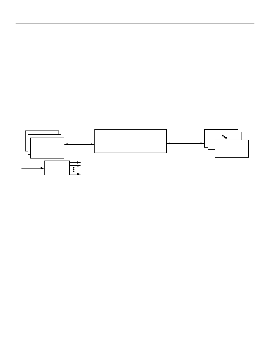
4.1 DS3/E3 to/from DS1/E1 Application
84 DS1s/48 E1s are input from LIUs, MUXed to DS3/E3, framed, and output to three DS3/E3 LIUs.
Similarly, three DS3s/E3s are input from the LIUs, deMUXed to the DS1/E1 level, and output as 84 DS1s/48 E1s.
The DS3/E3 will be received/transmitted by the device via the DS3DATAIN/OUT pins.
The DS1s/E1s will be received/transmitted by the device via the LINERX/TXDATA pins.
All three instances of the 28/21 channel M13/E13 MUXs are configured identically for M13/E13 mode.
All three instances of the 28/21 channel framers are configured identically for the transport mode of operation.
DS3 to/from E1 application is also possible.
Figure 4-1. x3 DS3s/E3s to/from 84 DS1s/48 E1s Configuration
ULTRAFRAMER
x3 DS3/E3
DS1/E1
84/48
DS1/E1 LIU
DS3/E3 LIU
CLK GEN
TSWC01622
REF CLK
TFRA84J13 Ultraframer
Product Description, Revision 4
DS3/E3/DS2/E2/DS1/E1/DS0
April 29, 2005
8
8
Agere Systems Inc..
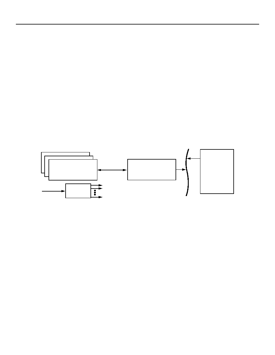
4.2 DS3/E3 to/from DS0/E0 Application
Figure 9-2 shows 2016 DS0/1536 E0s input via CHI or PSB. The DS0s/E0s are DS1/E1 framed, multiplexed to three DS3/
E3s, and then framed and output to DS3/E3 LIUs. The following points describe this scenario:
2016 DS0/1536 E0s are input from a switch, DS1/E1 framed, then MUXed to x3 DS3/E3. These are then framed and out-
put to three DS3/E3 LIUs.
Similarly, three DS3/E3s are input from the LIUs, deMUXed to the DS1/E1 level, and output as 2016 DS0/1536 E0s.
The DS3s/E3s will be received/transmitted by the device via the DS3DATAIN/OUT pins.
The DS0s/E0s will be received/transmitted by the device via the CHIRX/TXDATA pins.
The system interface can be the CHI (concentrated highway interface) or PSB (parallel system bus):
-- CHI can be programmed to operate at 8.192 MHz or 16.384 MHz clock and data rates.
-- The PSB interface consists of a 16-bit wide parallel bus operating at 19.44 Mbits/s.
All three instances of the 28/21 channel M13/E13 MUXs are configured identically for M13/E13 mode.
All three instances of the 28/21 channel framers are configured identically for switching mode of operation.
DS3 to/from E1 to/from E0 application is also possible (x3 DS3 to/from 2016 E0s).
Figure 4-2. x3 DS3s/E3s to/from 2016 DS0s/1536 E0s Configuration
SYSTEM INTERFACE
(CHI OR PSB)
ULTRAFRAMER
x3 DS3/E3
DS0/E0
SWITCH
CLK GEN
TSWC01622
REF CLK
DS3/E3 LIU
Product Description, Revision 4
TFRA84J13 Ultraframer
April 29, 2005
DS3/E3/DS2/E2/DS1/E1/DS0
Agere Systems Inc.
9
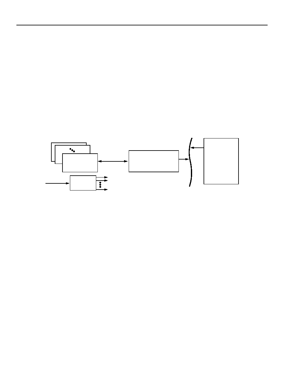
4.3 DS1/E1 to/from DS0/E0 Application
2016 DS0/E0s are input from a switch, DS1/E1 framed, and output to 84 DS1/63 E3 LIUs.
Similarly, 84 DS1s/63 E1s are input from the LIUs, deMUXed, and output as 2016 DS0s/E0s.
The DS1s/E1s will be received/transmitted by the device via the LINERX/TXDATA pins.
The DS0s/E0s will be received/transmitted by the device via the CHIRX/TXDATA pins.
The system interface can be the CHI (concentrated highway interface) or PSB (parallel system bus):
-- CHI can be programmed to operate at 8.192 MHz or 16.384 MHz clock and data rates.
-- The PSB interface consists of a 16-bit wide parallel bus operating at 19.44 Mbits/s.
All three instances of the 28/21 channel framers are configured identically for switching mode (DS1/E1 to/from DS0/E0)
of operation.
DS1/E1 level performance monitoring capabilities on all channels in the Rx direction (DS1/E1 to DS0/E0) of the signal
path.
Figure 4-3. 84 DS1s/63 E1s to/from 2016 DS0s/E0s Configuration
SYSTEM INTERFACE
(CHI OR PSB)
ULTRAFRAMER
DS1/E1
(2016)
DS0/E0
84/63
SWITCH
CLK GEN
TSWC01622
REF CLK
DS1/E1 LIU

TFRA84J13 Ultraframer
Product Description, Revision 4
DS3/E3/DS2/E2/DS1/E1/DS0
April 29, 2005
10
10
Agere Systems Inc..
5 Block Description
5.1 M13/E13 Multiplexer (M13/E13 MUX)
The M13/E13 block (three blocks per device) is a highly
configurable multiplexer/demultiplexer for which each block
can be configured for M13 or E13 operation. The features
are as described below.
5.1.1 M13 MUX
The M13 may operate in the C-bit parity or M23 mode, or a
mixed M13/M23 mode. In the C-bit parity mode, the M13
provides a far-end alarm and control (FEAC) code genera-
tor and receiver, an HDLC transmitter and receiver, and an
automatic far-end block error (FEBE) generator.
Each internal M12 MUX/deMUX and the M23 MUX/deMUX
can be configured to operate as independent MUXes/
deMUXes. 28 DS1 inputs (in groups of four) or 21 E1 input
signals (in groups of three) can feed into individual M12
MUXes, while the M23 MUX can take DS2 signals from
outputs of M12 MUXes, or direct DS2 inputs, or loopback
deMUXed DS2s.
The M13 supports numerous automatic monitoring func-
tions. It can provide an interrupt to the control system, or it
can operate in a polled mode.
The M13 complies with T1.102, T1.107, T1.231, T1.403,
T1.404, GR-499, G.747, and G.775.
5.1.1.1 Receive Direction
The receive DS3 is monitored for loss of clock and loss-of-
signal (LOS) according to T1.231. The B3ZS decoder
accepts either the unipolar clock and data, or unipolar clock
and positive and negative data. It also checks for bipolar
coding violations. The transmit DS3 can be looped back
into the receive side after B3ZS decoding. The M23 demul-
tiplexer checks for valid DS3 framing by finding the frame
alignment pattern (F-bits) and then locating the multiframe
alignment signal (M-bits). During each M frame, the data
stream is checked for the presence of the AIS (1010) or idle
(1100) pattern.
Within the M23 demultiplexer, there are four performance
monitoring counters for F-bit M-bit, P-bit, or E-bit parity, and
FEBE errors. Each M12 demultiplexer contains two perfor-
mance monitoring counters.
5.1.1.2 Transmit Direction
The incoming DS1/E1 clocks are first checked for activity or
loss-of-clock (LOC). The data signals are retimed and
checked for AIS and activity. DS1/E1 loopback selectors
allow the individual DS1/E1 signals within the received DS2
or DS3 to be looped back toward the DS2/DS3 input.
This loopback can be performed automatically, or the user
can force a DS1 or E1 loopback.
The four DS1 or three E1 signals for each M12 MUX are
fed into single-bit, 16-word-deep FIFOs to synchronize the
signals to the DS2 frame generation clock. The fill level of
each FIFO determines the need for bit stuffing its DS1/E1
input. The M13 can handle DS1/E1 signals with nominal
frequency offsets of �130 ppm and up to five unit intervals
peak jitter. The DS2/DS3 transmit clock is used to derive
the clock source for DS2 frame generation.
The M23 multiplexer generates a transmit DS3 frame, and
fills the information bits in the frame with data from the
seven DS2 select blocks.
The transmit DS3 output can either be in the form of unipo-
lar clock and data, or unipolar clock and positive and nega-
tive data. The DS3 data is B3ZS-encoded and can be
looped back from the receive DS3 input.
5.1.2 E13 MUX
The E13 is a functional block that performs MUX/deMUX
from/to 16 E1s, four E2s, and one E3 signal compliant with
ITU G.742 and ITU G.751. The E13 functional block is a
highly configurable multiplexer/demultiplexer. It can oper-
ate in E12, E13, or E23 modes. Each internal E12 MUX/
deMUX and E23 MUX/deMUX is independently config-
urable. The E3 inputs to the receive path can be HDB3-
encoded dual-rail (bipolar) signals or already decoded sin-
gle-rail signals with or without a BPV indication input. The
E1 and E2 inputs are expected to be decoded prior to the
E13 functional block. E3 transmit direction output can be
configured as HDB3-encoded dual rail (bipolar) or as single
rail.
The E13 provides status and two-level priority maskable
interrupt outputs to the microprocessor.
This block is also an independently configurable x4 E12
multiplexer/demultiplexer for up to 16 E1 signals to/from
four E2 signals, and has provisionable time-slot selection
for E1 and E2 insertion or drop via the multirate cross con-
nect functional block. E12/E23 multiplexers are capable of
generating alarm indicator signal (AIS) and remote alarm
indicator (RAI) signals.
E1 and E2 transmit path monitors detect loss-of-clock
(LOC) and AIS. The E2 receive path monitor detects LOC,
AIS, and RAI. The E3 receive monitor detects loss-of-signal
(LOS), LOC, bipolar violations (BPV), AIS, and RAI. E3 and
E2 loopback modes are also available.

Product Description, Revision 4
TFRA84J13 Ultraframer
April 29, 2005
DS3/E3/DS2/E2/DS1/E1/DS0
Agere Systems Inc.
11
5.2 Multirate Cross Connect (MRXC)
The multirate cross connect (MRXC) functional block (one
per device) is a crosspoint switch for DS1/J1/E1/DS2/E2
and DS3/E3 signals. The multirate cross connect routes
signals to/from the major functional blocks and external I/O
pins as necessary for each application. The MRXC can
multicast, route test patterns, idles, or alarm conditions to
any channel, and provide system loopbacks.
For DS1/E1 applications, the multirate cross connect can
interconnect up to 84 individual DS1/E1 channels between
the framer, M13/E13 multiplexer, jitter attenuator, or exter-
nal I/O. The external I/O pins support an application-depen-
dent mix of up to 86 DS1/E1* interfaces (allowing for
dedicated protection channels or additional DS1/E1 chan-
nels), 21 DS2 interfaces, or one of four available system
interfaces.
Independent signal paths for remote alarm indication (RAI)
and alarm indication signal (AIS) on channels between the
M13/E13 and the framer are supported.
The multirate cross connect has independent DS2 inter-
faces for the M12 and M23 subblocks of the M13 MUX. Full
split access to the external I/O device pins provides the
capability to add, drop, or rearrange the DS2 signals within
the M13.
The test-pattern generator/monitor functional block (TPG/
TPM) provides test signals and monitors inputs for signals
to/from the multirate cross connect. The TPG can generate
a set of test signals at DS1, E1, and DS2. There is only one
test pattern generator and monitor per signal rate.
The MRXC also provides the interface to the external pins.
The external pins may be configured to work in four modes:
a transport mode, a concentration highway interface (CHI)
mode, a parallel system bus (PSB) mode, and a network
serial multiplexed interface (NSMI) mode. The first mode is
used to provide dedicated access to the device for DS3/E3/
DS2/E2/DS1/E1 signals, and the last three modes are
described below.
Concentration highway interface (serial time-division
multiplex interface) CHI:
-- Global frame synchronization.
-- Global clock: 8.192 MHz or 16.384 MHz.
-- 18 transmit and 18 receive data ports; data rates:
8.192 Mbits/s or 16.384 Mbits/s.
Parallel system bus (parallel time-division multiplex inter-
face/transmit and receive) PSB:
-- Global frame synchronization.
-- Global clock: 19.44 MHz.
-- Data rate: 19.44 Mbits/s.
-- 8 bits of data + associated parity bit.
-- 4 bits of signaling + 2 bits of signaling control + 1 bit of
parity.
* The 85th and 86th DS1 I/O may only be used for protection channels
with applications in which the other 84 I/O are fixed (see MRXC section
of the Register Description for more information). Otherwise, applica-
tions are practically limited to 84 I/O.
Network serial multiplexed bus (NSMI):
-- Framer--NSMI payload assembled/disassembled into
DS1/E1s.
-- 6-pin or 8-pin serial interface.
-- Transmit and receive clock and data at 51.84 MHz.
-- Provides a minimal pin count interface for data and
inverse multiplexing for ATM (IMA) applications with-
out slip
buffers.
5.3 DS1 Digital Jitter Attenuator (DS1/E1 DJA)
The DS1/E1 digital jitter attenuator (DS1/E1 DJA) block
(three per device), contains 28 copies of the digital jitter
attenuator for a total of 84/63 DS1/E1 DJAs. These digital
jitter attenuator functional blocks can operate in two differ-
ent modes: as a DS1 or as an E1 jitter attenuator.
In both modes, the digital jitter attenuator can be provi-
sioned to always operate as a second-order PLL, or it can
switch to act as a first-order PLL during VT pointer adjust-
ments to help meet MTIE requirements. The period of time
in the first-order mode is provisionable. The PLL bandwidth
is provisionable between 0.1 Hz and 0.5 Hz, and the damp-
ing factor for these bandwidths varies between 2 and 0.5 to
accommodate a number of different system constraints.
The DS1/E1 DJA allows automatic pass-through of an AIS
from M13/E13 blocks.
5.4 Test Pattern Generator/Monitor (TPG/TPM)
The test pattern generator/test pattern monitor functional
block (TPG/TPM) consists of a set of configurable test pat-
tern generators and monitors for local self-test, mainte-
nance, and troubleshooting operations.
The TPG feeds one or more DS1/E1/DS2 test signals (via
data, clock, and FS (DS1/E1 only) or AIS signal paths) to
the multirate cross connect, which can redistribute or
broadcast these signals to any valid channel in the framer,
external I/O, or M13/E13 MUX.
Any channel arriving at the multirate cross connect can be
routed to the test monitor. The test monitor can automati-
cally detect/count bit errors in a pseudorandom test
sequence, loss of frame (DS1/E1 only), or loss of synchro-
nization situation. The TPM can provide an interrupt to the
control system, or it can be operated in a polled mode.
Simultaneous testing of DS1, E1, and DS2 signals is sup-
ported with one channel for each.
Supported test patterns are a quasirandom signal (QRSS),
a pseudorandom bit sequence (PRBS23, PRBS20,
PRBS15), alternating zeros/ones, an all-ones pattern, and
a 16-bit user-provisionable pattern.

Agere Systems Inc.
12
Product Description, Revision 4
TFRA84J13 Ultraframer
April 29, 2005
DS3/E3/DS2/E2/DS1/E1/DS0
The DS1 and E1 test patterns can be transmitted as either
unframed or as the payload of a framed signal, as defined
in ITU-T Recommendation O.150. DS2 patterns are
unframed only.
Under register control, single bit-errors can be injected into
any test pattern.
5.5 Clock Generator (CG)
The clock generator block may be used optionally to over-
ride the device configuration specified by the
MODE[2:0]_PLL device pins. If the block is not provisioned,
the default mode will generate all the necessary FRM block
PDH clocks, based upon the logic states on the
MODE[2:0]_PLL pins (see the Ultraframer Hardware
Design Guide).
5.6 Framer (FRM)
The DS1/J1/E1 framer block's (three per device) internal
components are described in the following sections. A par-
ticular application will determine which of the components
within the framer are used.
5.6.1 Line Decoder/Encoder
The line decoder/encoder supports either single-rail or
dual-rail transmission. In dual-rail mode, the line codes
supported are as follows:
Alternate mark inversion (AMI)
DS1 binary 8 zero code suppression (B8ZS)
ITU-CEPT high-density bipolar of order three (HDB3)
In the single-rail mode, a line interface unit (LIU) decodes/
encodes the data. In the dual-rail mode, loss-of-signal is
monitored.
In the case of coded mark inversion (CMI) coding (Japa-
nese TTC standard JJ-20.11), the LIU decodes the data,
listing both the CMI coding rule violations (CRVs) and line
coding violations as bipolar violations. (In the CMI mode,
the framer is in the single-rail mode.)
Note: Dual-rail mode is only supported for up to 18 DS1/E1
channels (out of 84/63).
5.6.2 Receive Frame Aligner/Transmit Frame Formatter
The receive frame aligner and transmit frame formatter
support the following frame formats:
D4 superframe
SF D4 superframe: F
T
framing only
J-D4 superframe with Japanese remote alarm
DDS
SLC-96
ESF
J-ESF (J1 standard with different CRC-6 algorithm)
Nonalign DS1 (193 bits--clear channel)
CEPT basic frame (ITU G.706)
CEPT CRC-4 multiframe with 100 ms timer (ITU G.706)
CEPT CRC-4 multiframe with 400 ms timer (automatic
CRC-4/non-CRC-4 equipment interworking) (ITU G.706
Annex B)
Nonalign E1 (256 bits--clear channel)
2.048 coded mark inversion (CMI) coded interface (TTC
standards JJ-20.11)
5.6.3 Receive Performance Monitor
The receive performance monitor detects the following
alarms:
Loss of receive clock
Loss-of-signal
Note: Only available on up to 18 individual DS1/E1
channels in dual-rail mode.
Loss-of-frame
Alarm indication signal (AIS)
Remote frame alarms
Remote multiframe alarms
These alarms are detected as defined by the appropriate
ANSI, AT&T, ITU, and ETSI standards. Performance moni-
toring, as specified by AT&T, ANSI, and ITU, is provided
through counters monitoring the following:
Bipolar violations
Note: Only available on up to 18 individual DS1/E1
channels.
Frame bit errors
CRC errors
Errored events
Errored seconds
Bursty errored seconds
Severely errored seconds
In-band loopback activation and deactivation codes can be
transmitted to the line via the payload or the facility data
link. In-band loopback activation and deactivation codes in
the payload or the facility data link are detected.

13
13
Agere Systems Inc.
TFRA84J13 Ultraframer
Product Description, Revision 4
DS3/E3/DS2/E2/DS1/E1/DS0
April 29, 2005
5.6.4 Signaling Processor
The signaling processor supports the following modes:
Superframe (D4, SLC-96): 2-state, 4-state, and 16-state
VT 1.5 SPE: 2-state, 4-state, and 16-state
Extended superframe: 2-state, 4-state, and 16-state
CEPT: common channel signaling (CCS) (TS-16)
Transparent (pass through) signaling
J-ESF handling groups
Signaling features supported per channel are as follows:
Signaling debounce
Signaling freeze
Signaling interrupt upon change of state
Associated signaling mode (ASM)
Signaling inhibit
Signaling stomp
Voice and data channels are programmable in the DS1
robbed-bit signaling modes. The entire payload can be
forced into a data-only (no signaling channels) mode i.e.,
transparent mode, achieved by programming one control
bit.
Signaling access occurs through the on-chip signaling reg-
isters or the system interface. Data and its associated sig-
naling information can be accessed through the system in
either DS1 or CEPT-E1 modes.
5.6.5 Facility Data Link (FDL) Processor
The receive facility data link processor monitors the bit-ori-
ented ESF data-link messages defined in ANSI T1.403.
The transmit facility data link unit overrides the FDL-FIFO
for the transmission of the bit-oriented ESF data-link mes-
sages defined in ANSI T1.403-1995.
The FDL processor extracts and stores data link bits from
three different frame types as follows:
D-bits and delineator bits from the SLC-96 multi-super-
frame.
Data link bits from DDS frames (bit 6 of time slot 24).
Two multiframes of Sa[4:8] bits from time slot 0 in CEPT
basic and CRC-4 multiframes.
The respective bits are always extracted from frame-
aligned frames and are stored in a stack. The processor
controls notification of stack updates through the interrupt
(maskable) registers.
The transmit FDL functional block performs the transmis-
sion of D-bits into SLC-96 superframes, Sa-bits in CEPT
frames, and D-bits in DDS frames.
In SLC-96 frames, the D and delineator bits are always
sourced from this functional block when the block is
enabled for insertion.
In DDS frames, the data link bits are always sourced
from this functional block when this block is enabled for
insertion. This functional block also provides the capabil-
ity to transmit BOMs (bit-oriented messages) in the data
link channel of ESF links.
In CEPT frames, the Sa bits are sourced from either the
Sa stack within this functional block or from the system
interface. The data link functional block only responds
with valid data when selected by the Sa source control
bits.
5.6.6 HDLC Unit
The HDLC processor formats the HDLC packets for inser-
tion into the programmable channels. A channel can be any
number of bits (1 to 8) from a time slot.
The maximum number of channels is 64. The maximum
channel bit rate is 64 kbits/s. The minimum channel bit rate
is 4 kbits/s. Each channel is allocated 128 bytes of storage.
HDLC processing of data on the facility data link (PRMs,
Sa-bits, or otherwise) is implemented by assigning the FDL
bit position to a logical HDLC channel.

Copyright � 2005 Agere Systems Inc.
All Rights Reserved
April 29, 2005
DS03-076BBAC-4 (Replaces DS03-076BBAC-3)
Product Description, Revision 4
TFRA84J13 Ultraframer
April 29, 2005
DS3/E3/DS2/E2/DS1/E1/DS0
Agere Systems Inc. reserves the right to make changes to the product(s) or information contained herein without notice. No liability is assumed as a result of their use or application.
Agere, Agere Systems, and the Agere logo are registered trademarks of Agere Systems Inc. Ultramapper is a trademark of Agere Systems Inc.
For additional information, contact your Agere Systems Account Manager or the following:
INTERNET:
Home: http://www.agere.com Sales: http://www.agere.com/sales
E-MAIL:
docmaster@agere.com
N. AMERICA: Agere Systems Inc., Lehigh Valley Central Campus, Room 10A-301C, 1110 American Parkway NE, Allentown, PA 18109-9138
1-800-372-2447, FAX 610-712-4106 (In CANADA: 1-800-553-2448, FAX 610-712-4106)
ASIA:
CHINA: (86) 21-54614688 (Shanghai), (86) 755-25881122 (Shenzhen)
JAPAN: (81) 3-5421-1600 (Tokyo), KOREA: (82) 2-767-1850 (Seoul), SINGAPORE: (65) 6741-9855, TAIWAN: (886) 2-2725-5858 (Taipei)
EUROPE:
Tel. (44) 1344 296 400
6 Glossary
AIS
Alarm indication signal
AMI
Alternate mark inversion
APS
Automatic protection switch
ASM
Associated signaling mode
BER
Bit error rate
BLSR
Bidirectional line switching ring
BOM
Bit-oriented message
BPV
Bipolar violation
B8ZS
Bipolar 8 zero substitution
CCI
Common channel signaling
CDR
Clock and data recovery
CHI
Concentrated highway interface
CMI
Coded mark inversion
CRC
Cyclic redundancy check
CRV
Coding rule violation
DACS
Digital access cross connects
DJA
Digital jitter attenuation
ESF
Extended superframe
EXZ
Excessive zeros
FCS
Frame check sequence
FDL
Facility data link
FEAC
Far-end alarm and control
FEBE
Far-end block error
HDB3
High-density bipolar of order three
HDLC
High-level data link control
LIU
Line interface unit
LOC
Loss-of-clock
LOF
Loss-of-frame
LOS
Loss-of-signal
LOPOH
Low-order path overhead
MCDR
Mate clock and data recovery
MRXC
Multirate cross connect
NSMI
Network serial multiplexed interface
OOF
Out of frame
PBGA
Plastic ball grid array
POAC
Path overhead access channel
PRBS
Pseudorandom bit sequence
PRM
Performance report message
QRSS
Quasirandom signal source
RAI
Remote alarm indicator
RDI
Remote defect indication
REI
Remote error indication
SDH
Synchronous digital hierarchy
SEF
Severely errored frame
TCM
Tandem connection monitoring
TOAC
Transport overhead access channels
UPSR
Unidirectional path switch ring
Telcordia and Telcordia Technologies are registered trademarks of Telcordia Technologies, Inc.
ANSI is a registered trademark of American National Standards Institute, Inc.
SLC is a registered trademark of Lucent Technologies Inc.
AT&T is a registered trademark of AT&T in the USA and other countries.
IEEE is a registered trademark of The Institute of Electrical and Electronics Engineers, Inc.