 | –≠–ª–µ–∫—Ç—Ä–æ–Ω–Ω—ã–π –∫–æ–º–ø–æ–Ω–µ–Ω—Ç: TSOT0410G | –°–∫–∞—á–∞—Ç—å:  PDF PDF  ZIP ZIP |
Document Outline
- Features
- General
- STS-192/STM-64
- Add/Drop
- Applications
- Description
- Block Diagram
- Figure 1. TSOT0410G Block Diagram
- Contact Us
Product Brief
November 1999
TSOT0410G SONET/SDH
STS-192 Overhead Processor and Path Terminator
Features
General
s
Section, line, and path overhead layer termination
for a SONET STS-192 (SDH STM-64) or four
STS-48 (STM-16) signals.
s
Supports any valid mix of STS-1 and concatenated
payloads from STS-3c to STS-192c.
s
Microprocessor interface configurable to operate
with most commercial microprocessors.
s
IEEE
*
1149.1 port with memory BIST, scan, and
boundary scan (JTAG).
s
Low-power 2.5 V operation with 3.3 V (5 V tolerant)
inputs and outputs.
s
600-pin LBGA package.
s
≠40
∞
C to +85
∞
C temperature range.
STS-192/STM-64
s
Provides a 16-bit (or 4
◊
4-bit) wide 622 MHz differ-
ential line interface.
s
Synchronizes to the receive data frames and
detects severely errored framing (SEF) and loss of
frame (LOF). It also inserts the framing bytes (A1,
A2) in the transmit data.
s
Supports enhanced framing (A1, A1, A2, A2).
s
Performs frame synchronous scrambling and
descrambling of the STS-192/STS-48 data, and
loss of signal (LOS) is detected.
s
Extracts the 64-byte or 16-byte section trace mes-
sage (J0) from the receive data and optionally
stores it in, or compares it to, an internal register
bank. Unstable or mismatched messages are
detected and path AIS may be optionally inserted
in the drop data.
s
Optionally inserts a 64-byte or 16-byte section
trace message or a fixed pattern in the J0 byte of
the transmit data.
s
Extracts, and outputs on a serial link, all transport
overhead bytes in the receive data and inserts any
or all transport overhead bytes in the transmit data
using a corresponding serial input.
s
Extracts, and outputs on serial links, the section
user channel (F1), orderwire channels (E1, E2),
and data communication channels (D1--D3 and
D4--D12) for the receive data. Inserts correspond-
ing serial input signals into the transmit data.
s
Extracts, integrates, and stores the automatic pro-
tection switch (APS) channel bytes (K1, K2) for the
receive data and detects protection switch failure
alarms. Inserts APS bytes in the transmit data from
internal registers or from overhead bytes in the add
data.
s
Detects line alarm indication signal (AIS) and
remote defect indication (RDI) based on the K2
byte of the receive data. Inserts line AIS and RDI in
the transmit data. Optionally inserts line RDI auto-
matically due to LOS, LOF, or line AIS defects.
s
Extracts, integrates, and stores the synchroniza-
tion status byte (S1) for the receive data. Inserts
the synchronization status byte into the transmit
data from an internal register or from a value
encoded on the transmit frame sync input.
s
Calculates, detects, and counts section and line
BIP-8 errors (B1, B2) for the receive data, and
inserts BIP-8 in the transmit data. Supports either
bit or block error accumulation, separately provi-
sionable.
s
Extracts and counts line remote errors (REI) for the
receive data (M1), and inserts REI in the transmit
data based on B2 errors (provisionable based on
bit or block errors).
*
IEEE
is a registered trademark of The Institute of Electrical and
Electronics Engineers, Inc.

2
Lucent Technologies Inc.
Product Brief
November 1999
STS-192 Overhead Processor and Path Terminator
TSOT0410G SONET/SDH
Features
(continued)
Add/Drop
s
Provides sixteen 1-bit serial 622 MHz (STS-12) dif-
ferential data links at the add and drop interfaces.
Path overhead and SPE timing indication is provided
by the drop interface. Clock recovery and data skew
compensation provided at the add interface.
s
Interprets the pointer bytes (H1, H2) for each receive
STS and detects loss of pointer (LOP) and path AIS.
Generates new pointer bytes in each drop STS to
adapt the receive data to the drop frequency and
phase. Pointer generation can be bypassed for syn-
chronous applications.
s
Optionally inserts path AIS in all drop STS pointer
bytes during LOS, LOF, SEF, or line AIS defects.
Optionally inserts path AIS in each drop STS due to
LOP or path AIS defects in the corresponding receive
STS, or under software control.
s
Inserts pointer bytes in the transmit data based on
values received in the transport overhead bytes of
the add data. Optionally inserts path AIS in each
transmit STS under control by software, or through
bits in the transport overhead of the add data.
s
Extracts the 64-byte or 16-byte path trace message
(J1) from up to four selectable receive STS channels
(one per STS-48), and stores it in an internal register
bank. Optionally compares the message to an
expected message stored in the internal register
bank and detects an unstable or mismatched mes-
sage.
s
Calculates, detects, and accumulates path BIP-8
errors (B3) for each receive STS (provisionable
based on bit or block errors). Provides signal fail
detection with provisionable BER.
s
Extracts and counts path REI for each receive STS
(G1).
s
Detects path unequipped, payload label mismatch
(PLM), and optionally, payload defect indication (PDI)
in the C2 byte of each receive STS. Optionally
inserts unequipped signal in each transmit STS
under software control.
s
Detects 1-bit and enhanced path RDI in each receive
STS (G1).
s
Outputs path alarm information for each receive STS
in the overhead bytes of the drop data (E1/F1).
Applications
s
SONET/SDH add-drop multiplex equipment
s
SONET/SDH terminal equipment
s
SONET/SDH digital cross connect equipment
s
SONET/SDH test equipment
s
ATM or packet over SONET/SDH equipment
Description
The TSOT0410G is used to terminate the transport
overhead in a single SONET STS-192 (SDH STM-64)
signal, or four SONET STS-48 (SDH STM-16) signals.
It monitors the STS path pointers and overhead in the
receive data, and provides timing signals for payload
mapping devices on the equipment side. The
TSOT0410G can be provisioned to support any mix of
STS-1 (AU-3) or STS-Nc (AU-4-Xc) payloads from a
single STS-192c (AU-4-64c) channel to 192 STS-1
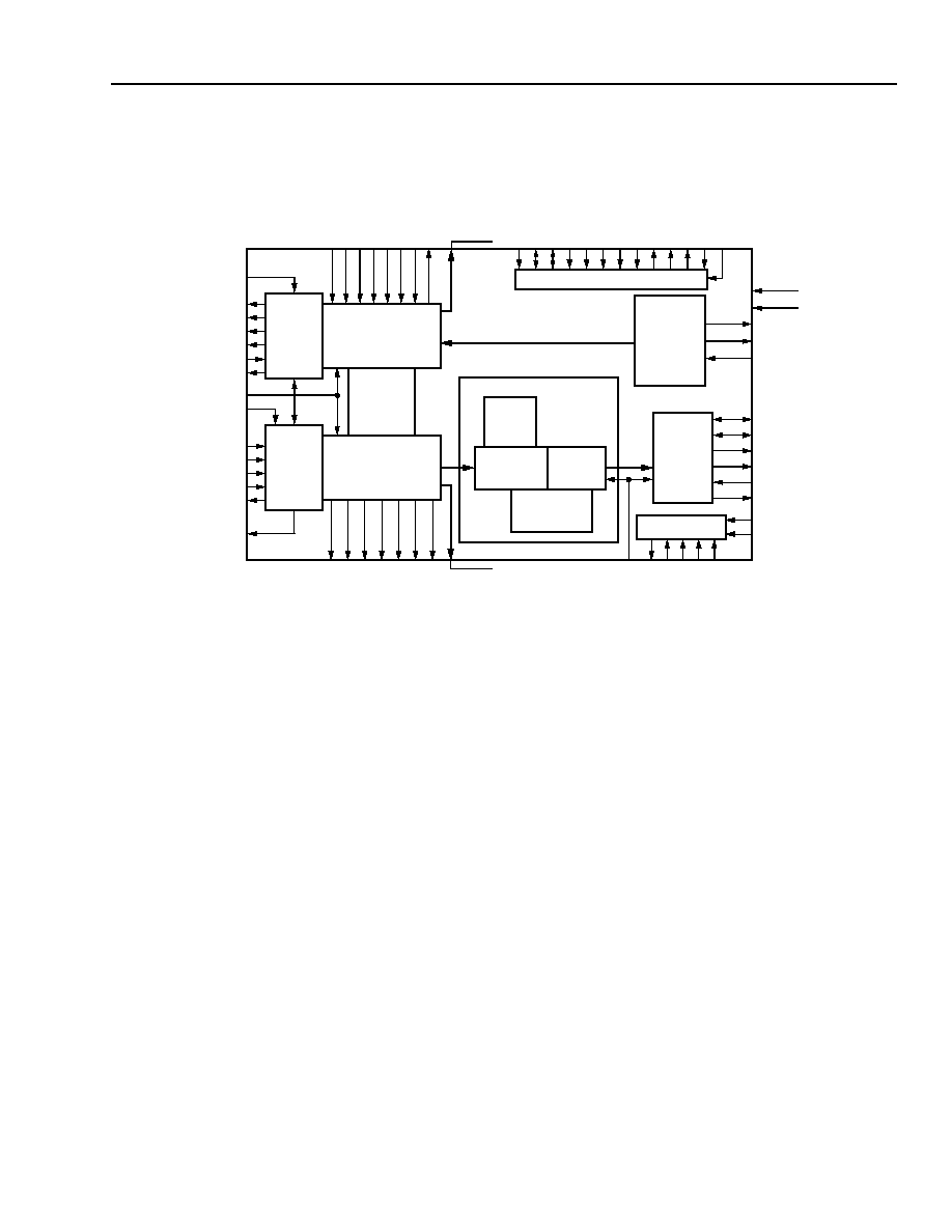
(AU-3) channels. An overall block diagram is shown in
Figure 1 on page 3.
The TSOT0410G is a 2.5 V, 0.25
µ
m high-density
device which is packaged in a 600-pin laminate ball
grid array (LBGA). The I/O circuitry uses a 3.3 V
0.25
µ
m technology (5 V tolerant).
The microprocessor interface allows an external pro-
cessor to access the TSOT0410G for configuration and
maintenance. The microprocessor interface is
designed to support various 16-bit microprocessors
with minimal glue logic.
The TSOT0410G includes an
IEEE
1149.1 compliant
JTAG port to support boundary scan and memory BIST
testing of the device.
Lucent Technologies Inc.
3
Product Brief
November 1999
STS-192 Overhead Processor and Path Terminator
TSOT0410G SONET/SDH
Block Diagram
5-7982(F)r.3
Figure 1. TSOT0410G Block Diagram
TRANSMIT
STS-192
LINE
INTERFACE
TD_1_[3:0]
TD_2_[3:0]
TD_3_[3:0]
TD_4_[3:0]
STS_MODE
RECEIVE
STS-192
LINE
INTERFACE
RD_1_[3:0]
RD_2_[3:0]
RD_3_[3:0]
RD_4_[3:0]
STS-48 RECEIVE
TRANSPORT OVERHEAD
PROCESSOR
STS-48 TRANSMIT
TRANSPORT OVERHEAD
PROCESSOR
SECTION
TRACE
BUFFER
X4
X4
X4
RECEIVE PATH
OVERHEAD
PROCESSOR
RECEIVE
DROP
ALIGNER
RECEIVE
POINTER
PROCESSOR
PATH
TRACE
BUFFER
STS PATH
PROCESSING
BLOCK
RECEIVE
PAYLOAD
DROP
INTERFACE
JTAG INTERFACE
DFRM
D_CLK
DDATA_[16:1]
DCTL_[1--4]
TD
O
TD
I
TC
K
TM
S
TR
S
T
_N
TRANSMIT
PAYLOAD
ADD
INTERFACE
TADCC_[16:1]
TADCK
ADATA_[16:1]
T
O
H_
CL
K_
[1
--4
]
T
O
HF
P
_
[1--4
]
T
O
HE
N_
[1
--4
]
T
O
HDA
T
_
[1--4
]_[1:0
]
T
L
DCC_
[1
--4
]
T
S
DCC_
[1
--4
]
T
S
U
S
E
R
_[1--4]
TE
XPO
W_
[
1
--
4
]
T
L
C
L
OW
_[1
--
4]
T
O
W_CLK
_
[1
--4]
T
S
D_
CL
K_
[1
--4
]
T
L
D_
CL
K
_
[
1
--4
]
MICROPROCESSOR INTERFACE
P
A
R
IT
Y
_
[1:0
]
DAT
A
_
[
1
5
:0
]
ADDRE
SS_
[1
5
:
0
]
CS_
N
TS
_N
DS_
N
RW_
N
MP
MO
D
E
RL
CL
OW_
[
1
--
4
]
R
E
X
P
OW
_
[
1--4]
R
S
U
S
E
R
_
[
1--4]
RSD
CC_
[1
--4
]
RL
D
CC_
[1
--4
]
ROHDA
T
_
[1--4]_[
1
:0]
ROHF
P
_
[1
--4
]
ROH_
CL
K_
[1
--4
]
ROW_
CL
K_
[1
--4
]
RSD_
CL
K_
[1
--4
]
RL
D_
CL
K_
[1
--4
]
T_CLK
TFRM
T_CLKO_[1--4]
R_CLK_[1--4]
RFRM[1--4]
DRP
BYP
X4
X4
SCANEN_N
TSTMD_N
RDDCC_[16:1]
RDDCK_[1--4]
X4
PCL
K
TA
_N
TE
A_
N
INT
_
N
PM
_
C
L
K
R_CLKO_[1--4]
RST_N
HIZ_N

Lucent Technologies Inc. reserves the right to make changes to the product(s) or information contained herein without notice. No liability is assumed as a result of their use or application. No
rights under any patent accompany the sale of any such product(s) or information.
Copyright © 1999 Lucent Technologies Inc.
All Rights Reserved
November 1999
PN99-122SONT
For additional information, contact your Microelectronics Group Account Manager or the following:
INTERNET:
http://www.lucent.com/micro
E-MAIL:
docmaster@micro.lucent.com
N. AMERICA:
Microelectronics Group, Lucent Technologies Inc., 555 Union Boulevard, Room 30L-15P-BA, Allentown, PA 18103
1-800-372-2447, FAX 610-712-4106 (In CANADA: 1-800-553-2448, FAX 610-712-4106)
ASIA PACIFIC: Microelectronics Group, Lucent Technologies Singapore Pte. Ltd., 77 Science Park Drive, #03-18 Cintech III, Singapore 118256
Tel. (65) 778 8833, FAX (65) 777 7495
CHINA:
Microelectronics Group, Lucent Technologies (China) Co., Ltd., A-F2, 23/F, Zao Fong Universe Building, 1800 Zhong Shan Xi Road, Shanghai
200233 P. R. China Tel. (86) 21 6440 0468, ext. 316, FAX (86) 21 6440 0652
JAPAN:
Microelectronics Group, Lucent Technologies Japan Ltd., 7-18, Higashi-Gotanda 2-chome, Shinagawa-ku, Tokyo 141, Japan
Tel. (81) 3 5421 1600, FAX (81) 3 5421 1700
EUROPE:
Data Requests: MICROELECTRONICS GROUP DATALINE: Tel. (44) 7000 582 368, FAX (44) 1189 328 148
Technical Inquiries: GERMANY: (49) 89 95086 0 (Munich), UNITED KINGDOM: (44) 1344 865 900 (Ascot),
FRANCE: (33) 1 40 83 68 00 (Paris), SWEDEN: (46) 8 594 607 00 (Stockholm), FINLAND: (358) 9 4354 2800 (Helsinki),
ITALY: (39) 02 6608131 (Milan), SPAIN: (34) 1 807 1441 (Madrid)