Preliminary Data Sheet
April 2003
PSC1534 Lithium-Ion Linear Battery Charger
Features
s
Low external component count and small footprint
s
Charge termination indication and manual shut-
down using PROG pin
s
Programmable charge current: 200 mA to 800 mA
s
4.1 V or 4.2 V preset voltages
s
Automatic trickle charging at I
PROG
/10 for heavily
discharged batteries requires no additional exter-
nal components
s
Very low quiescent battery current during shut-
down and standby (charger removed)
s
Charger undervoltage lockout and battery over-
voltage lockout
s
Overcurrent/overtemperature protection
s
Low-profile (1 mm) SOT-23 package
Description
The PSC1534 is a constant-current/constant-voltage
Li-Ion battery charger controller that is functionally
equivalent and performance equivalent to the
LTC
�
1734. As an enhancement, the PSC1534 also
includes automatic detection and trickle charging of
deeply discharged batteries (V
BAT
<2.42 V).
The PSC1534 allows charge current programming
using a single external resistor, R
PROG
. The voltage
on the PROG pin is proportional to the charging cur-
rent at the I
SENSE
pin, allowing the user to use an
external A/D to monitor charging progress. A low bat-
tery drain (BAT pin) manual shutdown state can be
forced by floating the PROG pin. When the input sup-
ply (V
IN
) is removed, the PSC1534 enters a very low-
current sleep mode, during which BAT input supply
current is <1
�
A.
Applications
s
Any application that requires a compact, low-cost
solution for Li-Ion battery charging
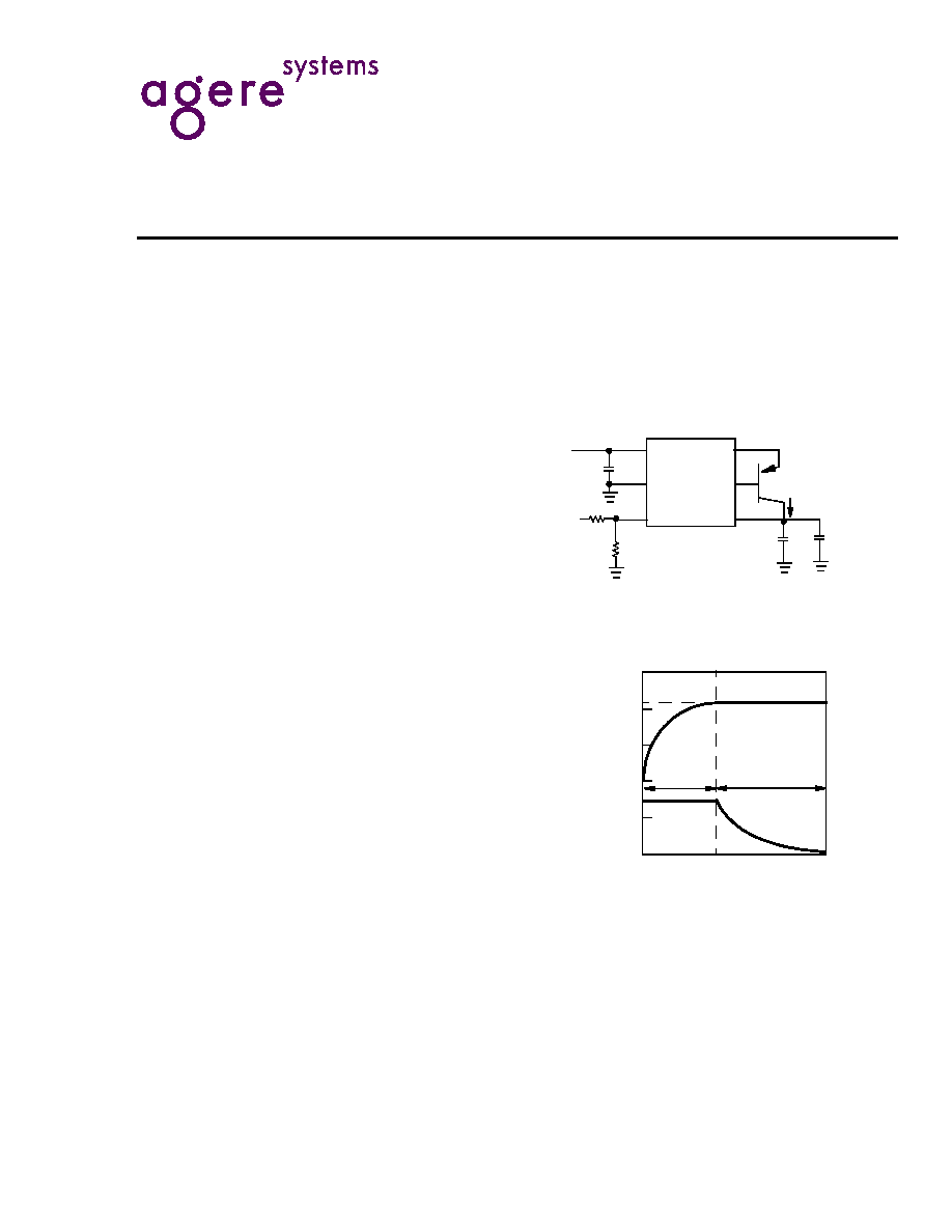
Typical Application
Figure 1. 500 mA Li-Ion Battery Charger
Figure 2. PROG Pin Indicates Charge Status
V
IN
5 V
V
CC
3
2
R
PROG
3 k
4
1
�
F
PROG
GND
I
SENSE
DRIVE
BAT
PSC1534
1
6
5
FMMT549
I
BAT
= 500 mA
SINGLE
Li-Ion
BATTERY
10
�
F
+
10 k
To A/D
CHARGING
COMPLETE
CHARGING
BEGINS
0 V
1 V
2 V
3 V
4 V
5 V
V
PRO
G
(V
)
V
BA
T
(V)
1.5 V
CONSTANT
VOLTAGE
CONSTANT
CURRENT
V
BAT
V
PROG
2
2
Agere Systems Inc.
Preliminary Data Sheet
April 2003
PSC1534 Lithium-Ion Linear Battery Charger
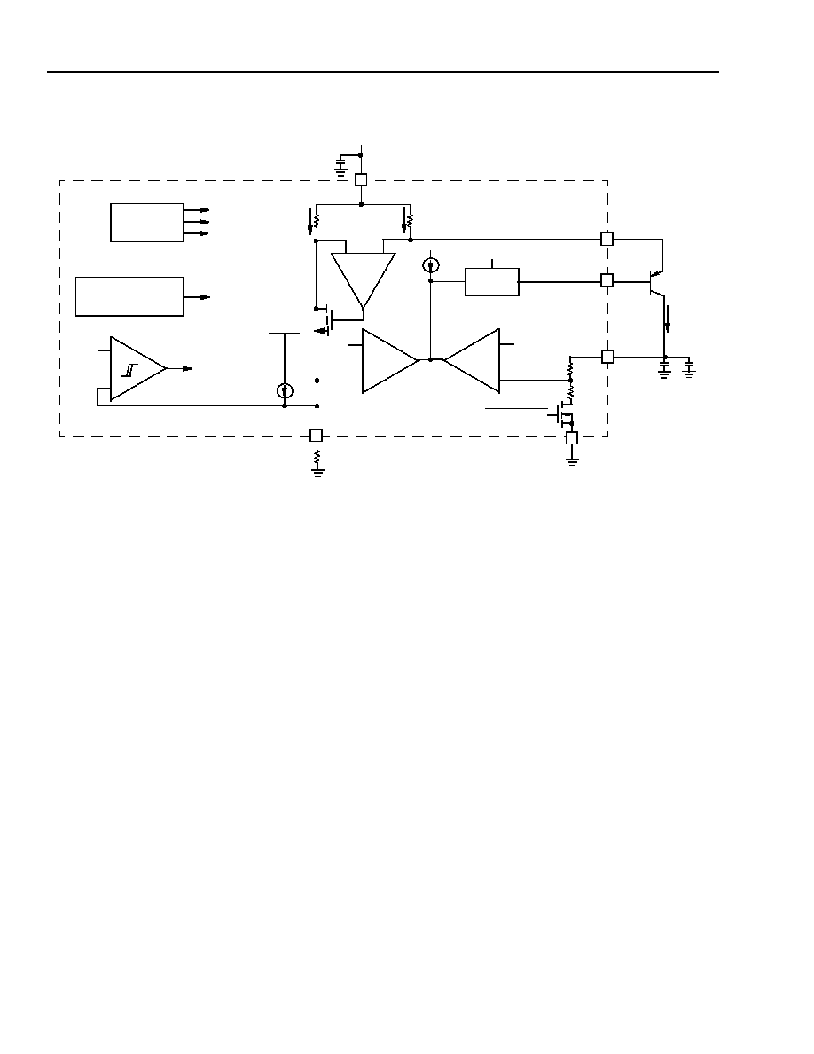
Block Diagram
Figure 3. PSC1534 Block Diagram
VOLTAGE
REFERENCE
UVLO
SHUTDOWN
+
2.15 V
�
SHDN CMP
3
�
A
4
SHUTDOWN
�
�
�
+
OAI2
OAV1
OAI1
V
IN
3
V
CC
90
I
BAT
/1000
0.09
I
BAT
1
�
F
1
I
SENSE
PNP
DRIVER
6
DRIVE
SHUTDOWN
2.5 V
5
BAT
10
�
F
SINGLE
Li-Ion
CELL
I
BAT
PROG
R
PROG
2
GND
SHUTDOWN
1.5 V
1.5 V
2.5 V
TEMP. LIMIT
CURRENT LIMIT
2.15 V
FMMT529
Agere Systems Inc.
3
Preliminary Data Sheet
April 2003
PSC1534 Lithium-Ion Linear Battery Charger
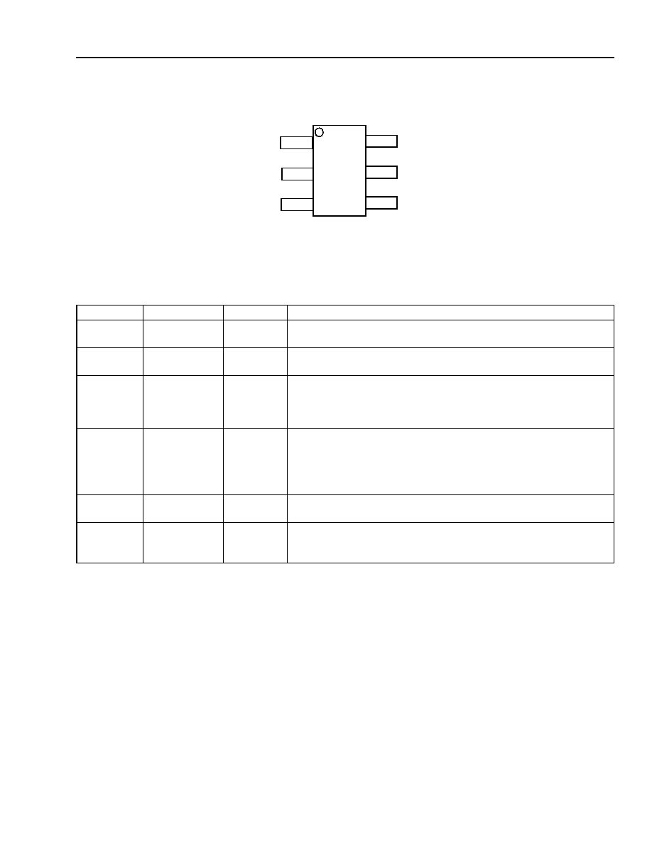
Pin Information
Figure 4. S6 Package, 6-Lead Plastic, 1 mm Thick, SOT-23
Table 1. Pin Descriptions
Pin Number
Signal Name
Type
Description
1
I
SENSE
Output
Charging current sense node. Supplies a monitored and controlled
current from V
CC
to the PNP emitter.
2
GND
GND
Ground reference for all internal circuits. Kelvin connects battery
ground to GND to minimize battery top-off voltage error.
3
V
CC
Supply
Positive input supply for all internal circuits and external charging
current (PNP emitter). The internal charging current control loop
monitors and controls the current flow between V
CC
and I
SENSE
.
Bypass this pin to GND with a 1
�
F to 10
�
F tantalum capacitor.
4
PROG
I/O
Charge current programming pin. Use an external resistor, R
PROG
,
to set current-mode charging current. I
CHRG
= 1.5 V/R
PROG
. If the
voltage on PROG exceeds 2.15 V, the PSC1534 enters manual
shutdown mode. This pin can be monitored by an external A/D con-
verter.
5
BAT
I/O
Battery voltage sense input. Bypass this pin with a 10
�
F tantalum
capacitor close to BAT and GND.
6
DRIVE
Output
Output base driver for PNP transistor. This driver output is current
limited and monitored by an internal thermal shutdown circuit that
will disable the driver if high-current fault conditions occur.
T
JMAX
= 125 �C,
JA
= 230 �C/W
TOP VIEW
6 DRIVE
5 BAT
4 PROG
I
SENSE
1
GND 2
V
CC
3
4
4
Agere Systems Inc.
Preliminary Data Sheet
April 2003
PSC1534 Lithium-Ion Linear Battery Charger
Absolute Maximum Ratings
Stresses in excess of the absolute maximum ratings can cause permanent damage to the device. These are abso-
lute stress ratings only. Functional operation of the device is not implied at these or any other conditions in excess
of those given in the operational sections of the data sheet. Exposure to absolute maximum ratings for extended
periods can adversely affect device reliability.
Table 1. Absolute Maximum Ratings
*
*
Absolute maximum ratings are those values beyond which the life of a device may be impaired.
Parameter
Value
Unit
Supply Voltage (V
CC
)
�0.3 to +6.5
V
Input Voltage (BAT, PROG)
�0.3 to (V
CC
+ 0.3)
V
Output Voltage (DRIVE)
�0.3 to (V
CC
+ 0.3)
V
Output Current (I
SENSE
)
�900
mA
Short-circuit Duration (DRIVE)
Indefinite
--
Junction Temperature
125
�C
Operating Ambient Temperature Range
Some electrical characteristics are guaranteed by design and statistical process control.
�40 to +85
�C
Operating Junction Temperature
100 �C
Storage Temperature Range
�65 to +150
�C
Lead Temperature (soldering, 10 s)
300
�C
Agere Systems Inc.
5
Preliminary Data Sheet
April 2003
PSC1534 Lithium-Ion Linear Battery Charger
Electrical Characteristics
In Table 2, specifications are at T
A
= 25 �C. V
CC
= 5 V, GND = 0 V, and V
BAT
= V
FLOAT
unless otherwise noted.
Bold text highlights the specifications that apply over the �40 �C to +85 �C operating temperature range.
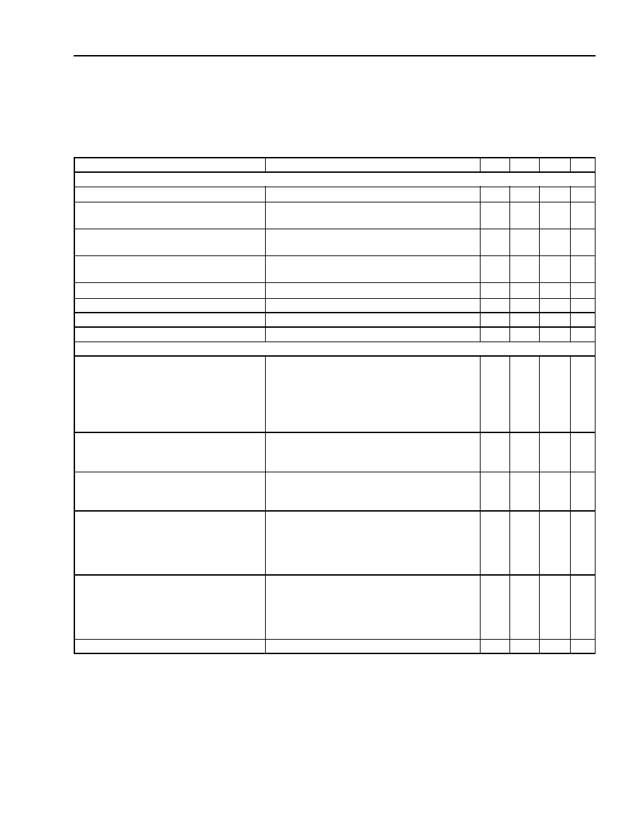
Table 2. Electrical Characteristics
Parameter
Conditions
Min
Typ
Max Unit
V
CC
Supply
Operating Supply Range
*
*
When operating near minimum
V
CC
, a low V
ce-sat
PNP transistor is required.
--
4.55
--
6.0
V
Quiescent V
CC
Pin Supply Current
V
BAT
= 5 V, (forces I
DRIVE
= I
BAT
= 0),
I
PROG
= 200
�
A, (7500
from PROG to GND)
--
550
1150
�
A
V
CC
Pin Supply Current in Manual
Shutdown
PROG pin open
--
350
900
�
A
Battery Drain Current in Manual
Shutdown
External PNP pass transistor has negligible I
b-c
when the V
b-c
= 0.8 V (V
CC
� V
BAT
= 5.0--4.2 = 0.8 V).
PROG pin open
�2
0.2
2
�
A
Battery Drain Current in Sleep Mode
External PNP pass transistor has negligible I
b-e
when the V
b-e
= 4.2 V (V
BAT
� V
CC
= 4.2--0 = 4.2 V).
V
CC
= 0 V
�2
0.2
2
�
A
Undervoltage Lockout Exit Threshold
V
CC
increasing
4.45 4.56
4.68
V
Undervoltage Lockout Entry Threshold
V
CC
decreasing
4.30 4.41
4.53
V
Undervoltage Lockout Hysteresis
V
CC
decreasing
--
150
--
mV
Charging Performance
Output Float Voltage in Constant
Voltage Mode
4.1 V version,
I
BAT
= 10 mA,
4.55 V
V
CC
5.5 V,
4.2 V version,
I
BAT
= 10 mA,
4.55 V
V
CC
5.5 V
4.059
4.158
4.10
4.20
4.141
4.242
V
V
Output Full-scale Current When
Programmed for 200 mA in Constant
Current Mode
R
PROG
= 7500
,
4.55 V
V
CC
5.5 V,
pass PNP beta > 50
155
200
240
mA
Output Full-scale Current When
Programmed for 700 mA in Constant
Current Mode
R
PROG
= 2143
,
4.55 V
V
CC
5.5 V,
pass PNP beta > 50
620
700
770
mA
Current Monitor Voltage on PROG Pin
I
BAT
= 10% of I
BAT1
,
R
PROG
= 7500
4.55 V
V
CC
5.5 V,
pass PNP beta > 50,
0 �C
T
A
85 �C
0.025 0.15
0.30
V
Current Monitor Voltage on PROG Pin
I
BAT
= 10% of I
BAT2
,
R
PROG
= 2143
,
4.55 V
V
CC
5.5 V,
pass PNP beta > 50,
0 �C
T
A
85 �C
0.08 0.15
0.22
V
Drive Output Current
V
DRIVE
= 3.5 V
30
--
--
mA
6
6
Agere Systems Inc.
Preliminary Data Sheet
April 2003
PSC1534 Lithium-Ion Linear Battery Charger
Electrical Characteristics
(continued)
When operating near minimum
V
CC
, a low V
ce-sat
PNP transistor is required.
External PNP pass transistor has negligible I
b-c
when the V
b-c
= 0.8 V (V
CC
� V
BAT
= 5.0--4.2 = 0.8 V).
� External PNP pass transistor has negligible I
b-e
when the V
b-e
= 4.2 V (V
BAT
� V
CC
= 4.2--0 = 4.2 V).
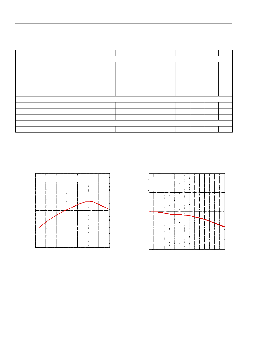
Typical Performance Characteristics
Figure 5. Float Voltage vs. Temperature
Figure 6. V
FLOAT
vs. I
BAT
(R
PROG
= 2 k
)
Table 2. Electrical Characteristics (continued)
Parameter
Conditions
Min
Typ
Max
Unit
Automatic Trickle Charging
Trickle Charge Battery Voltage Entry Threshold
V
BAT
decreasing
2.32
2.42
2.52
V
Trickle Charge Battery Voltage Exit Threshold
V
BAT
increasing
2.42
2.52
2.62
V
Trickle Charge Battery Voltage Hysteresis
--
--
100
--
mV
Trickle Charge--Charge Current
R
PROG
= 3000
,
4.55 V
V
CC
5.5 V,
pass PNP beta > 50
10
50
90
mA
Charger Manual Control
Manual Shutdown Threshold
V
PROG
increasing
2.05
2.15
2.25
V
Manual Shutdown Hysteresis
V
PROG
decreasing from V
MSDT
--
90
--
mV
Programming Pin Pull-up Current
V
PROG
= 2.5 V
�6
�3
�1.5
�
A
Protection
Drive Output Short-circuit Current Limit
V
DRIVE
= V
CC
35
65
130
mA
4.180
4.190
4.200
4.210
4.220
-50
-25
0
25
50
75
100
125
V
float
(V
CC
=5V, I
BAT
=10 mA, PNP=FCX717)
V
Fl
o
a
t
Temperature (C)
4.195
4.197
4.200
4.202
4.205
0
100
200
300
400
500
600
700
V
FLO
A
T
(V
)
I
BAT
(mA)
V
cc
=5V
T
A
=25C
PNP=FCX717
Agere Systems Inc.
7
Preliminary Data Sheet
April 2003
PSC1534 Lithium-Ion Linear Battery Charger
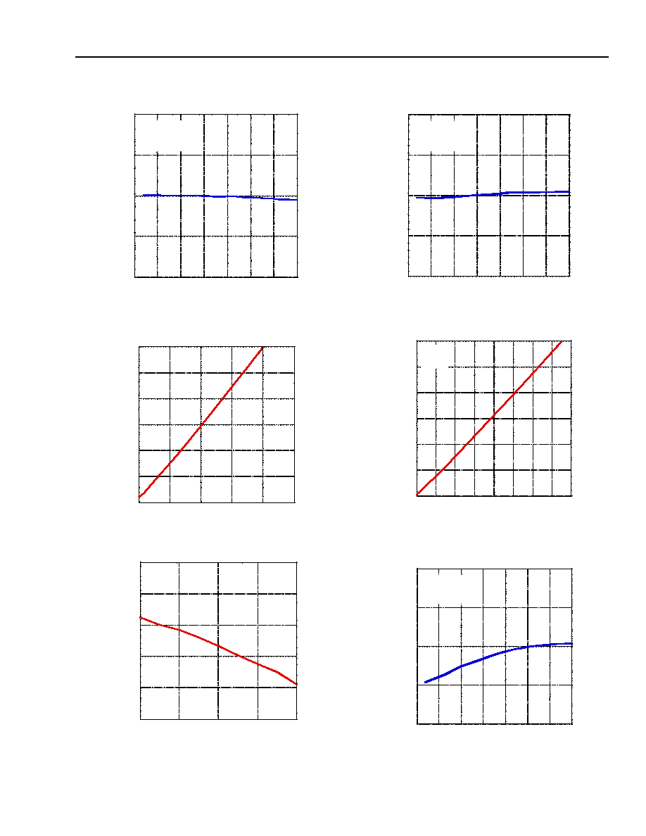
Typical Performance Characteristics
(continued)
Figure 7. I
BAT1
vs. Temperature, R
PROG
= 7.5 k
Figure 8. V
PROG
vs. I
BAT1
(R
PROG
= 7.5 k
)
Figure 9. I
PROG_PU
vs. V
CC
Figure 10. I
BAT1
vs. Temperature, R
PROG
= 2 k
Figure 11. V
PROG
vs. I
BAT
(R
PROG
= 2 k
)
Figure 12. I
PROG_PU
vs. Temperature
180.0
190.0
200.0
210.0
220.0
-50
-25
0
25
50
75
100
125
I
BA
T
(mA
)
Temperature (C)
V
CC
=5.0V,
R
PROG
=7.5 kOhms
PNP=FCX717
0.000
0.2500
0.5000
0.7500
1.000
1.250
1.500
0
50
100
150
200
250
V
PRO
G
(V
)
I
BAT
(mA)
R=7.5 kohms
T
A
=25C,
V
CC
=5V
2.600
2.800
3.000
3.200
3.400
3.600
2
3
4
5
6
I
PRO
G
Pu
l
l
-
U
p
(
u
A)
V
PROG
(V)
V
CC
=6V
T
A
=25C
700.0
725.0
750.0
775.0
800.0
-50
-25
0
25
50
75
100
125
I
BA
T
(mA
)
Temperature (C)
V
CC
=5.0V
R
PROG
=2 kOhms
PNP=FCX717
0.000
0.2500
0.5000
0.7500
1.000
1.250
1.500
0
100
200
300
400
500
600
700
800
V
PR
O
G
(V
)
I
BAT
(mA)
R=2 kohms
T
A
=25C,
V
CC
=5V
2.000
2.500
3.000
3.500
4.000
-50
-25
0
25
50
75
100
125
I
PR
O
G
(u
A
)
Temperature (C)
V
CC
=5.0V
R
PROG
=3 kOhms
PNP=FCX717
Agere Systems Inc. reserves the right to make changes to the product(s) or information contained herein without notice. No liability is assumed as a result of their use or application. Agere,
Agere Systems, and the Agere logo are trademarks of Agere Systems Inc.
Copyright � 2003 Agere Systems Inc.
All Rights Reserved
April 2003
DS02-365MTD
For additional information, contact your Agere Systems Account Manager or the following:
INTERNET:
http://www.agere.com
E-MAIL:
docmaster@agere.com
N. AMERICA:
Agere Systems Inc., Lehigh Valley Central Campus, Room 10A-301C, 1110 American Parkway NE, Allentown, PA 18109-9138
1-800-372-2447, FAX 610-712-4106 (In CANADA: 1-800-553-2448, FAX 610-712-4106)
ASIA:
Agere Systems Hong Kong Ltd., Suites 3201 & 3210-12, 32/F, Tower 2, The Gateway, Harbour City, Kowloon
Tel. (852) 3129-2000, FAX (852) 3129-2020
CHINA: (86) 21-5047-1212 (Shanghai), (86) 755-25881122 (Shenzhen)
JAPAN: (81) 3-5421-1600 (Tokyo), KOREA: (82) 2-767-1850 (Seoul), SINGAPORE: (65) 6778-8833, TAIWAN: (886) 2-2725-5858 (Taipei)
EUROPE:
Tel. (44) 7000 624624, FAX (44) 1344 488 045
Preliminary Data Sheet
April 2003
PSC1534 Lithium-Ion Linear Battery Charger
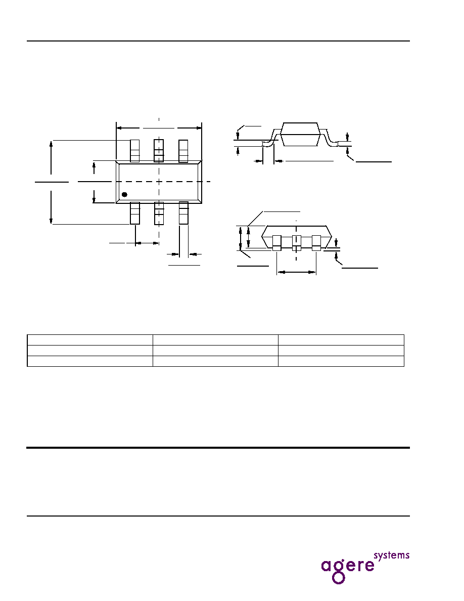
Package Description
S6 Package, 6-Lead Plastic SOT-23
All dimensions are in millimeters.
Ordering Information
LTC and LT are registered trademarks of Linear Technology Corporation.
Table 3. Ordering Information
Device Version
Part Order Number
SOT-23-6 Package Marking
PSC1534-4.1
700045365
Axxx
PSC1534-4.2
700045383
Lxxx
PIN 1 ID
0.25--0.50
(0.010--0.020)
2.60--3.00
(0.102--0.118)
1.50--1.75
(0.059--0.069)
2.80--3.10
(0.110--0.118)
0.95
(0.037)
REF
(6 PLCS)
0.09--0.20
(0.004--0.008)
1.00 MAX
(0.039 MAX)
0.30--0.50 REF
(0.012--0.019 REF)
0.01-- 0.10
(0.0004--0.004)
0.20
(0.008)
0.80--0.90
(0.031--0.035)