Description
These slim font seven segment
displays incorporate a new slim
font character design. This slim
font features narrow width,
specially mitered segments to
give a fuller appearance to the
illuminated character. Faces of
these displays are painted a
neutral gray for enhanced on/off
contrast.
Agilent HDSP-301x/303x Series
HDSP-561x/563x Series
10 mm and 13 mm Slim Font
Seven Segment Displays
Data Sheet
Features
∑ Excellent appearance
∑ Slim font design
∑ Mitered corners, evenly
illuminated segments
∑ Gray face for optimum on/off
contrast
∑ Choice of colors: HER, green,
yellow, and AlGaAs
∑ Choice of character size: 10 mm
and 13 mm
∑ Characterized for luminous
intensity
Devices
HER
Green
Yellow
AlGaAs
HDSP-
HDSP-
HDSP-
HDSP-
Description
301E
301G
301Y
301A
Common Anode, 10 mm Display
303E
303G
303Y
303A
Common Cathode, 10 mm Display
561E
561G
561Y
561A
Common Anode, 13 mm Display
563E
563G
563Y
563A
Common Cathode, 13 mm Display
All devices are available in either
common anode or common
cathode configuration with right
hand decimal point.
2
Part Numbering System
5082 - x xx x - x x x xx
HDSP - x xx x - x x x xx
Mechanical Options
[1]
00: No Mechanical Option
Color Bin Options
[1,2]
0: No Color Bin Limitation
Maximum Intensity Bin
[1,2]
0: No Maximum Intensity Bin Limitation
Minimum Intensity Bin
[1,2]
0: No Minimum Intensity Bin Limitation
Device Configuration/Color
[1]
A: AlGaAs Red
E: High Efficiency Red
G: Green
Y: Yellow
Device Specific Configuration
[1]
Refer to Respective Data Sheet
Package
[1]
Refer to Respective Data Sheet
Notes:
1. For codes not listed in the figure above, please refer to the respective data sheet or contact your nearest Agilent representative
for details.
2. Bin options refer to shippable bins for a part-number. Color and Intensity Binbs are typically restricted to 1 bin per tube
(exceptions may apply). Please refer to respective data sheet for specific bin limit information.
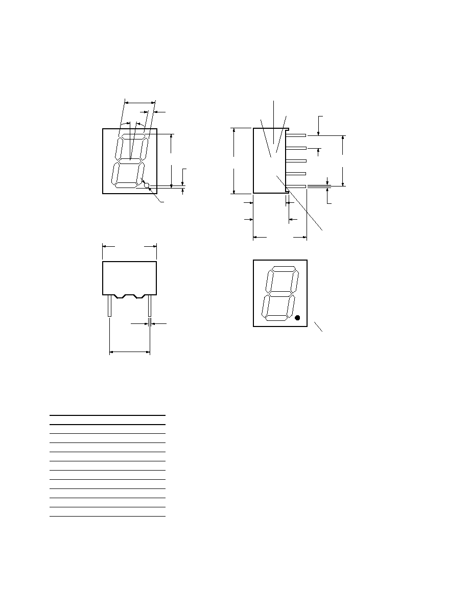
3
HDSP-301x/303x Series
Pin
Function
1
G
2
F
3
Common A/C
4
E
5
D
6
DP
7
C
8
Common A/C
9
B
10
A
12.80
±
0.25
(0.504)
7.00
±
0.25
(0.276)
6.40
±
0.25
(0.252)
10.40 MIN.
(0.409)
LUMINOUS
INTENSITY
CATEGORY
PIN 6
NOTE: QDSP-399G DOES NOT HAVE PIN 6.
COUNTRY
OF ORIGIN
COLOR BIN
DATE CODE
9.70
±
0.25
(0.382)
TOP SIDE
FRONT VIEW
RIGHT SIDE
0.30
±
0.05
(0.012)
7.62
±
0.38
(0.300)
1.20
(0.047)
ÿ
6.00
(0.236)
10.00
∞
0.90
(0.035)
10.00
(0.394)
1.85
(0.073)
4 x 2.54
(0.400)
0.53
±
0.05
(0.021)
2.54
±
0.38
(0.100)
A
DP
B
C
F
E
G
D
1
2
3
4
5
10
9
8
7
6
HDSP-XXXX
YWW XZ COO
+
+
+
+
+
+
+
+
+
+
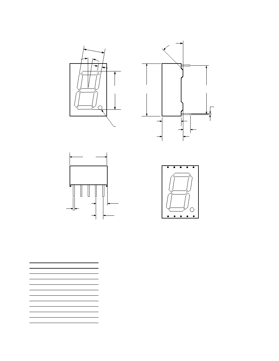
4
HDSP-561x/563x Series
Pin
Function
1
E
2
D
3
Common A/C
4
C
5
DP
6
B
7
A
8
Common A/C
9
F
10
G
12.25 ± 0.25
(0.482)
1.25
(0.049)
ÿ
7.40
(0.292)
1.25
(0.049)
10∞
13.00
(0.512)
17.50 ± 0.3/≠0.25
(0.689)
6.40 ± 0.25
(0.252)
7.00 ± 0.25
(0.276)
3.60 ± 0.3
(0.142)
15.24 ± 0.3
(0.600)
0.29 ± 0.08 TYP.
(0.011)
45∞
a
DP
b
c
f
e
g
d
10
9
8
7
6
1
2
3
4
5
0.58 ± 0.08
(0.023)
3.59 ± 0.3 TYP.
(0.141)
2.54 ± 0.3 TYP.
(0.100)
NOTES:
1. ALL DIMENSIONS ARE IN MILLIMETERS (INCHES).
2. UNLESS OTHERWISE STATED, TOLERANCES ARE ±0.25 mm.
5
Absolute Maximum Ratings
Description
HER
Green
Yellow
AlGaAs
Units
Average Power per Segment or DP
105
105
105
37
mW
Peak Forward Current per Segment or DP
90
90
90
45
mA
DC Forward Current per Segment or DP
30
30
30
15
mA
Operating Temperature Range
≠40 to +80
≠40 to +80
≠40 to +80
≠20 to +80
∞C
Storage Temperature Range
≠40 to +80
≠40 to +80
≠40 to +80
≠40 to +80
∞C
Reverse Voltage per Segment or DP
5
5
5
5
V
Wavesoldering Temperature for 3 Seconds
250
250
250
250
∞C
1.59 mm below body
Notes:
1. Derate above 33∞C at 0.34 mA/∞C for HER.
2. Derate above 27∞C at 0.32 mA/∞C for Green.
3. Derate above 30∞C at 0.33 mA/∞C for Yellow.
4. Derate above 60∞C at 0.25 mA/∞C for AlGaAs.
HER
Device
Series
HDSP-
Parameter
Symbol
Min.
Typ.
Max.
Units
Test Conditions
561/563E
Luminous Intensity/Segment
I
V
2.001
3.526
mcd
I
F
= 10 mA
(Digit Average)
Forward Voltage/Segment
V
F
1.90
2.50
V
I
F
= 20 mA
or DP
Peak Wavelength
PEAK
635
nm
I
F
= 20 mA
Dominant Wavelength
d
625
nm
I
F
= 20 mA
Reverse Current
I
R
100
µ
A
V
R
= 5 V
Thermal Resistance LED
R
J≠PIN
351.5
∞C/W/Seg.
Junction-to-Pin
Electrical/Optical Characteristics at T
A
= 25∞C
HER
Device
Series
HDSP-
Parameter
Symbol
Min.
Typ.
Max.
Units
Test Conditions
301/303E
Luminous Intensity/Segment
I
V
1.251
2.000
mcd
I
F
= 10 mA
(Digit Average)
Forward Voltage/Segment
V
F
1.90
2.50
V
I
F
= 20 mA
or DP
Peak Wavelength
PEAK
635
nm
I
F
= 20 mA
Dominant Wavelength
d
625
nm
I
F
= 20 mA
Reverse Current
I
R
100
µ
A
V
R
= 5 V
Thermal Resistance LED
R
J≠PIN
351.5
∞C/W/Seg.
Junction-to-Pin