Description
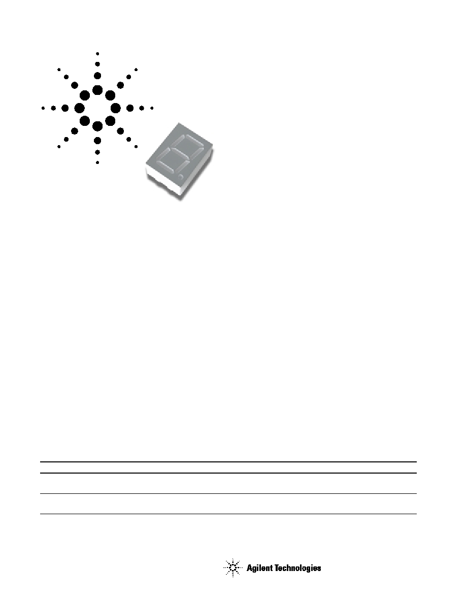
This 10.16 mm (0.4 inch) LED
single digit seven segment display
uses industry standard size package
and pinout. The device is available
in either common anode or common
cathode. The choice of colors
includes High Efficiency Red
(HER), Green, AlGaAs Red, and
Yellow. The gray face displays are
suitable for indoor use.
Agilent HDSP-311x/313x
10.16 mm (0.4 inch) Single Digit General
Purpose Seven Segment Display
Data Sheet
Applications
∑ Suitable for indoor use
∑ Not recommended for industrial
application, i.e., operating
temperature requirements
exceeding +85∞C or below ≠25∞C
[1]
∑ Extreme temperature cycling not
recommended
Note:
1. For additional details, please contact your
local Agilent sales office or an authorized
distributor.
Devices
HER
Green
AlGaAs Red
Yellow
Description
Package Drawing
HDSP-311E
HDSP-311G
HDSP-311A
HDSP-311Y
Common Anode Right
A
Hand Decimal
HDSP-313E
HDSP-313G
HDSP-313A
HDSP-313Y
Common Cathode Right
B
Hand Decimal
Features
∑ Industry standard size
∑ Industry standard pinout
10.16 mm (0.4 inch) character height
DIP lead on 2.54 mm
∑ Choice of colors
High Efficiency Red (HER), Green,
AlGaAs Red, and Yellow
∑ Excellent appearance
Evenly lighted segments gray
package gives optimum contrast
± 50 ft. viewing angle
∑ Design flexibility
Common anode right hand
decimal point or common cathode
right hand decimal point
∑ Categorized for luminous
intensity
Green and yellow categorized for
color
2
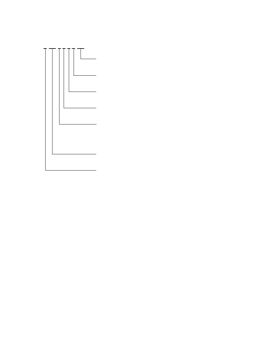
Part Numbering System
Notes:
1. For codes not listed in the figure above, please refer to the respective datasheet or contact your nearest
Agilent representative for details.
2. Bin options refer to shippable bins for a part number. Color and Intensity Bins are typically restricted to 1
bin per tube (exceptions may apply). Please refer to respective datasheet for specific bin limit information.
5082 -X X X X-X X X X X
HDSP-X X X X-X X X X X
Mechanical Options
[1]
00: No Mechanical Option
Color Bin Options
[1,2]
0: No Color Bin Limitation
Maximum Intensity Bin
[1,2]
0: No Maximum Intensity Bin Limitation
Minimum Intensity Bin
[1,2]
0: No Minimum Intensity Bin Limitation
Device Configuration/Color
[1]
A: AlGaAs Red
E: High Efficiency Red
G: Green
Y: Yellow
Device Specific Configuration
[1]
Refer to Respective Datasheet
Package
[1]
Refer to Respective Datasheet
3
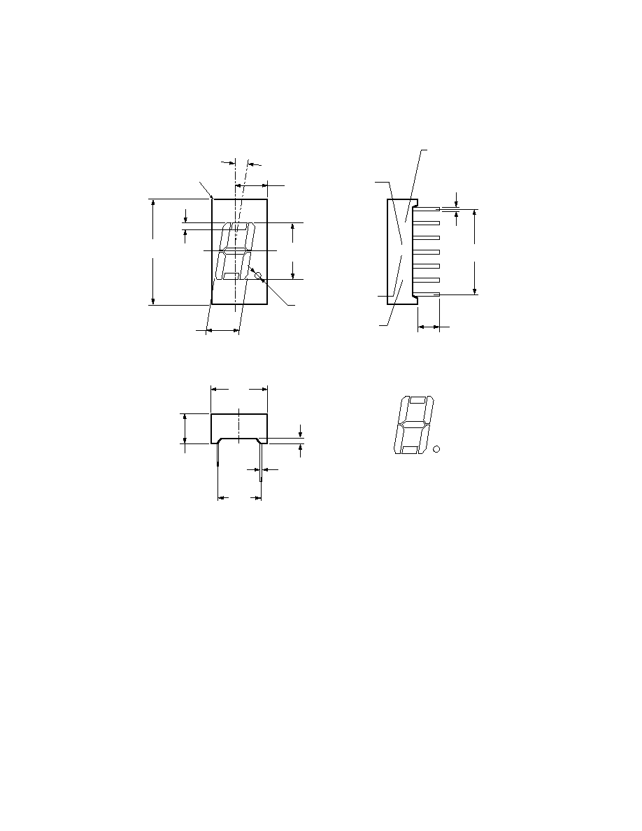
Package Dimensions
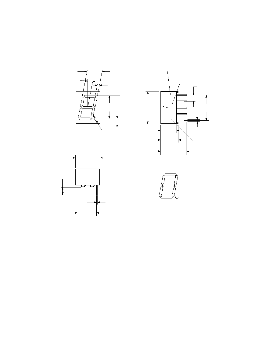
Package Drawing A
18.75
(0.738)
1.20
(0.047)
10.16
(0.400)
5.51
(0.220)
1.4
(0.55)
5.54
(0.218)
8∞
FRONT VIEW
HDSP-XXXX
YWW XZ COO
0.50
(0.020)
2.54 x 6
(0.100)
4.10
(0.161)
DATE CODE
COLOR
BINNING
(NOTE 3)
LUMINOUS
INTENSITY
CATEGORY
COUNTRY
OF ORIGIN
TOP END VIEW
7.62
(0.300)
0.30
(0.012)
5.10
(0.201)
0.60
(0.020)
SIDE VIEW
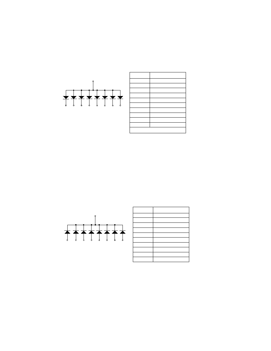
A
F
G
B
C
DP
D
E
NOTE: NO PINS 4, 5, 6, AND 12
DIMENSIONS IN MILLIMETERS (INCHES)
9.80
(0.386)
+
PIN 1


