Features
∑ Industry Standard Size
∑ Industry Standard Pinout
7.62 mm (0.300 inch) DIP Leads
on 2.54 mm (0.100 inch) Centers
∑ Choice of Colors
AlGaAs Red, High Efficiency Red,
Yellow, Green
∑ Excellent Appearance
Evenly Lighted Segments
±
50
∞
Viewing Angle
Optimum Contrast Given by
Gray Top Surface for AlGaAs Red
and Green Devices
Red Top Surface for HER Devices
Yellow Top Surface for Yellow
Devices
∑ Design Flexibility
Common Anode or
Common Cathode
Single Digits
Left or Right Hand Decimal Point
±
1. Overflow Character
∑ Categorized for Luminous
Intensity
Yellow and Green Categorized for
Color
Use of Like Categories Yields a
Uniform Display
∑ High Light Output
∑ High Peak Current
∑ Excellent for Long Digit String
Multiplexing
∑ Intensity and Color Selection
Available
See Intensity and Color Selected
Displays Data Sheet
∑ Sunlight Viewable AlGaAs
AlGaAs
[1]
HER
[1]
Yellow
Green
Package
Red HDSP-
5082-
5082-
HDSP-
Description
Drawing
7610
7620
3600
7.6 mm Common Anode Left Hand Decimal
A
7611
7621
3601
7.6 mm Common Anode Right Hand Decimal
B
7613
7623
3603
7.6 mm Common Cathode Right Hand Decimal
C
7616
7626
3606
7.6 mm Universal
±
1. Overflow Right Hand Decimal
[2]
D
E150
7650
7660
4600
10.9 mm Common Anode Left Hand Decimal
E
E151
7651
7661
4601
10.9 mm Common Anode Right Hand Decimal
F
E153
7653
7663
4603
10.9 mm Common Cathode Right Hand Decimal
G
E156
7656
7666
4606
10.9 mm Universal
±
1. Overflow Right Hand Decimal
[2]
H
Notes:
1. These displays are recommended for high ambient light operation. Please refer to the HDSP-E10X AlGaAs and HDSP-335X HER data
sheet for low current operation.
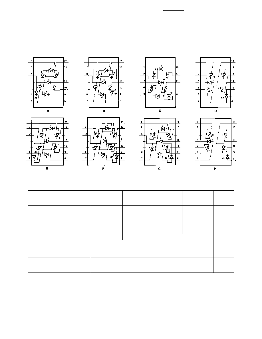
2. Universal pinout brings the anode and cathode of each segment's LED out to separate pins. See internal diagram D.
3. Universal pinout brings the anode and cathode of each segment's LED out to separate pins. See internal diagram H.
Devices
5082-761x Series
5082-762x Series
5082-765x Series
5082-766x Series
HDSP-360x Series
HDSP-460x Series
HDSP-E15x Series
7.6 mm (0.3 inch)/10.9 mm
(0.43 inch) Seven Segment
Displays
Technical Data
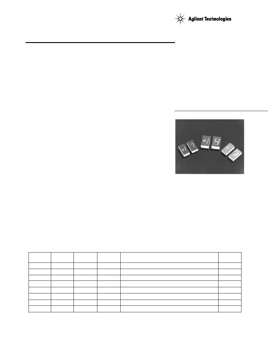
Description
The 7.6 mm (0.3 inch) and 10.9
mm (0.43 inch) LED seven
segment displays are designed for
viewing distances up to 3 metres
(10 feet) and 5 metres (16 feet).
These devices use an industry
standard size package and
pinouts. All devices are available
as either common anode or
common cathode.
2
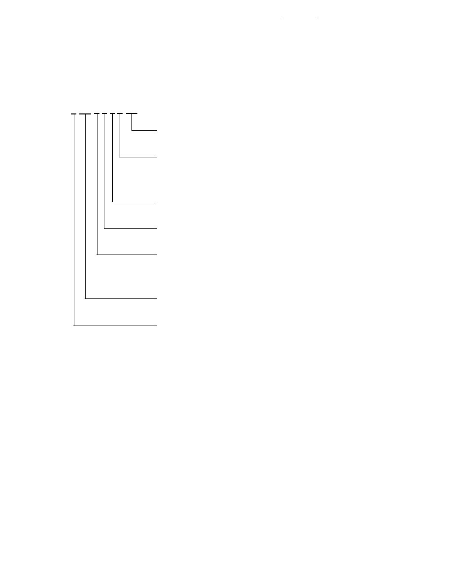
Part Numbering System
Notes:
1. For codes not listed in the figure above, please refer to the respective datasheet or contact your nearest
Agilent representative for details.
2. Bin options refer to shippable bins for a part number. Color and Intensity Bins are typically restricted to 1
bin per tube (exceptions may apply). Please refer to respective datasheet for specific bin limit information.
5082 -X X X X-X X X X X
HDSP-X X X X-X X X X X
Mechanical Options
[1]
00: No Mechanical Option
Color Bin Options
[1,2]
0: No Color Bin Limitation
4: Color Bin 4 Only (applicable for Green devices only)
B: Color Bins 2 and 3 (applicable for Yellow devices only)
Maximum Intensity Bin
[1,2]
0: No Maximum Intensity Bin Limitation
Minimum Intensity Bin
[1,2]
0: No Minimum Intensity Bin Limitation
Device Configuration/Color
[1]
0: Common Anode
1: Common Anode
3: Common Cathode
Device Specific Configuration
[1]
Refer to Respective Datasheet
Package
[1]
E: 10.9 mm (0.43 inch) Single Digit Seven Segment Display
3
displays are ideal for portable
applications. The high light
ambient displays are ideal for
high light ambients or long string
lengths. For additional informa-
tion see the Low Current Seven
Segment Displays, or High Light
Ambient Seven Segment Displays
data sheets.
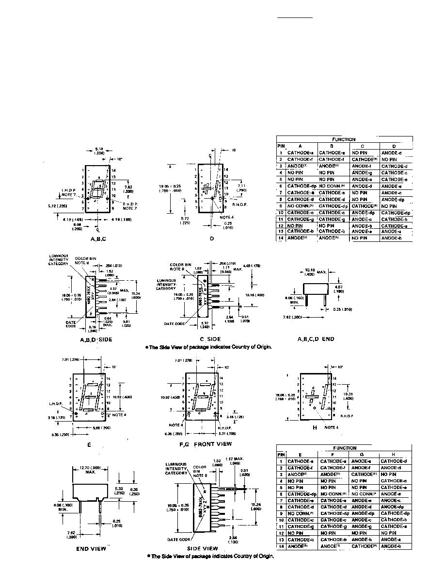
NOTES;
1. DIMENSIONS IN
MILLIMETRES AND
(INCHES).
2. ALL UNTOLERANCED
DIMENSIONS ARE
FOR REFERENCE
ONLY.
3. REDUNDANT
ANODES.
4. UNUSED DP
POSITION.
5. SEE INTERNAL
CIRCUIT DIAGRAM.
6. REDUNDANT
CATHODE.
7. SEE PART NUMBER
TABLE FOR L.H.D.P.
AND R.H.D.P.
DESIGNATION.
8. FOR YELLOW AND
GREEN DEVICES
ONLY.
Package Dimensions
These displays are ideal for most
applications. Pin for pin equiva-
lent displays are also available in
a low current or high light
ambient design. The low current
4
Internal Circuit Diagram
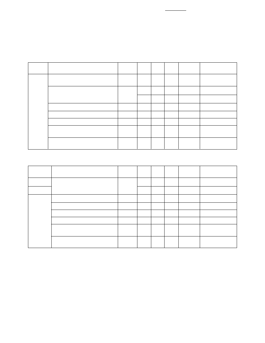
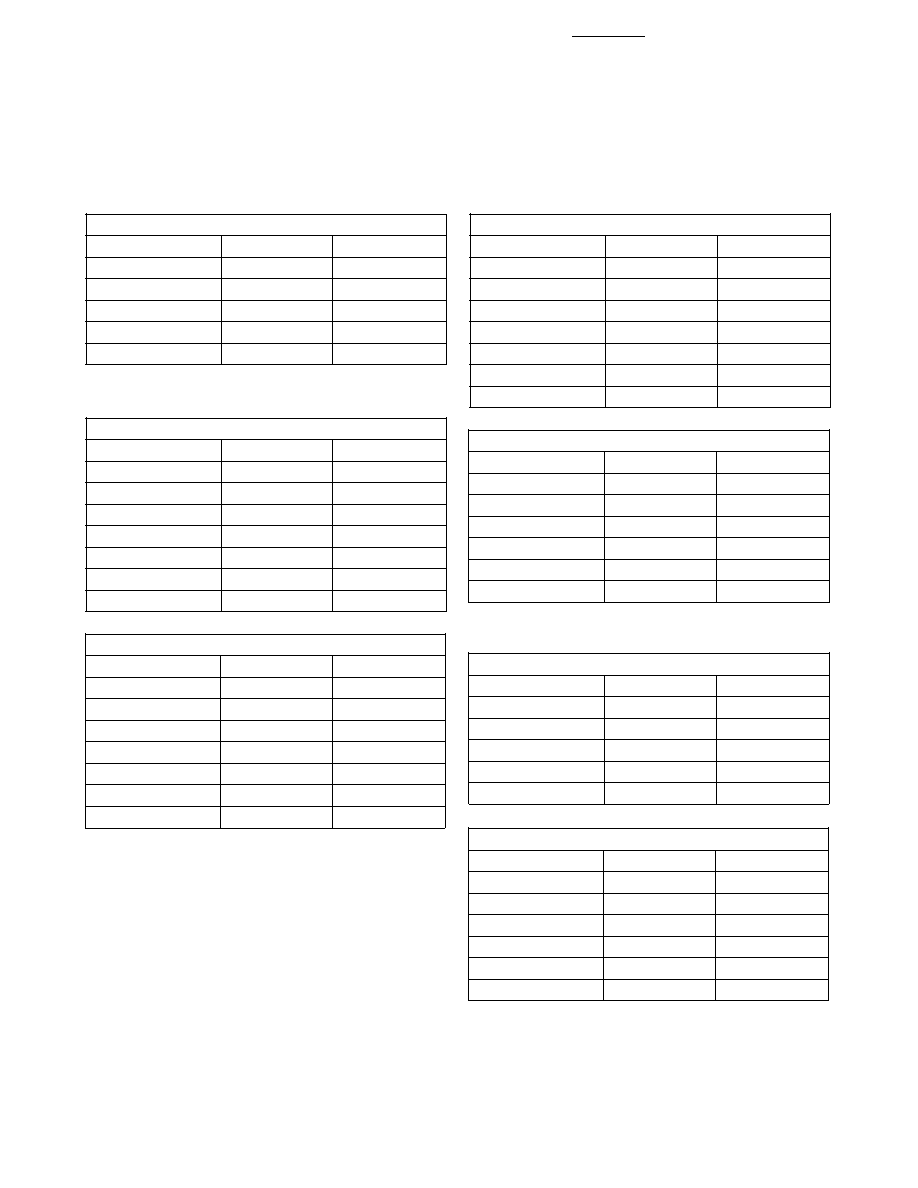
Absolute Maximum Ratings
AlGaAs Red
HER
Yellow
Green
HDSP-E150
5082-7610/
5082-7620/
HDSP-3600/
Description
Series
7650 Series
7660 Series
4600 Series
Units
Average Power per Segment or DP
96
105
80
105
mW
Peak Forward Current per
160
[1]
90
[3]
60
[5]
90
[7]
mA
Segment or DP
DC Forward Current per
40
[2]
30
[4]
20
[6]
30
[8]
mA
Segment or DP
Operating Temperature Range
-20 to +100
[9]
-40 to +100
∞
C
Storage Temperature Range
-55 to +100
∞
C
Reverse Voltage per
3.0
V
Segment or DP
Wave Soldering Temperature for
3 Seconds (1.59 mm [0.063 in.]
250
∞
C
below Body)
Notes:
1. See Figure 1 to establish pulsed conditions.
2. Derate above 46
∞
C at 0.54 mA/
∞
C.
3. See Figure 6 to establish pulsed conditions.
4. Derate above 53
∞
C at 0.45 mA/
∞
C.
5. See Figure 7 to establish pulsed conditions.
6. Derate above 81
∞
C at 0.52 mA/
∞
C.
7. See Figure 8 to establish pulsed conditions.
8. Derate above 39
∞
C at 0.37 mA/
∞
C.
9. For operation below -20
∞
C, contact your local Agilent components sales office or an authorized distributor.
5
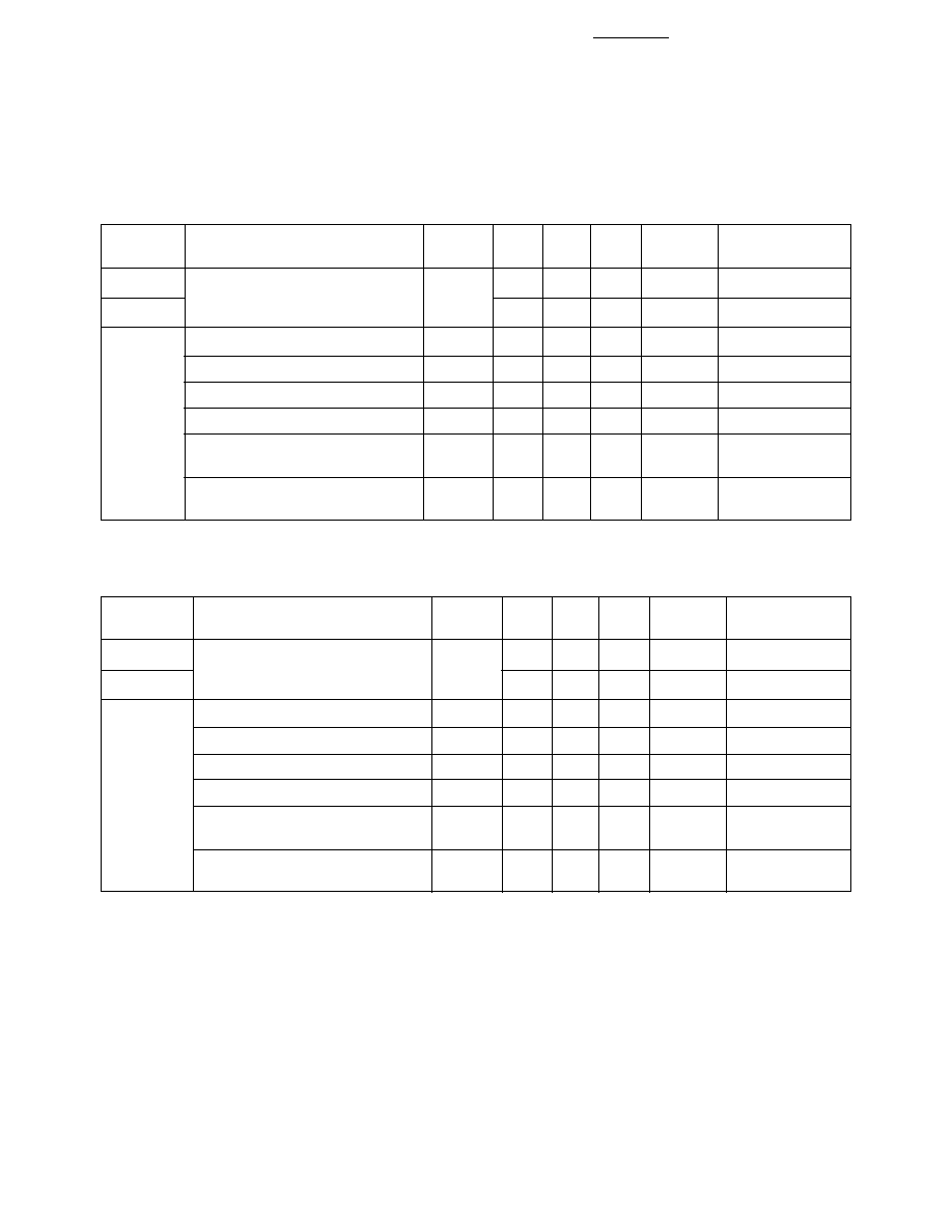
Electrical/Optical Characteristics at T
A
= 25
∞
C
Device
Series
Parameter
Symbol
Min.
Typ.
Max.
Units
Test Conditions
Luminous Intensity/Segment
[1, 2, 5]
I
V
8.5
15.0
mcd
I
F
= 20 mA
(Digit Average)
1.8
V
I
F
= 20 mA
Forward Voltage/Segment or DP
V
F
2.0
3.0
V
I
F
= 100 mA
HDSP-
E15x
Peak Wavelength
PEAK
645
nm
Dominant Wavelength
[3]
d
637
nm
Reverse Voltage/Segment or DP
[4]
V
R
3.0
15
V
I
R
= 100
µ
A
Temperature Coefficient of
V
F
/
∞
C
-2
mV/
∞
C
V
F
/Segment or DP
Thermal Resistance LED Junction-
R
J-PIN
340
∞
C/W/Seg
to-Pin
AlGaAs Red
Device
Series
Parameter
Symbol
Min.
Typ.
Max.
Units
Test Conditions
5082-761x
Luminous Intensity/Segment
[1,2,6]
340
800
µ
cd
I
F
= 5 mA
(Digit Average)
I
V
5082-765x
340
1115
µ
cd
I
F
= 5 mA
Forward Voltage/Segment or DP
V
F
2.1
2.5
V
I
F
= 20 mA
Peak Wavelength
PEAK
635
nm
Dominant Wavelength
[3]
d
626
nm
All
Reverse Voltage/Segment or DP
[4]
V
R
3.0
30
V
I
R
= 100
µ
A
Temperature Coefficient of
V
F
/
∞
C
-2
mV/
∞
C
V
F
/Segment or DP
Thermal Resistance LED
R
J-PIN
280
∞
C/W
Junction-to-Pin
High Efficiency Red
6
Device
Series
Parameter
Symbol
Min.
Typ.
Max.
Units
Test Conditions
5082-762x
Luminous Intensity/Segment
[1,2]
205
620
µ
cd
I
F
= 5 mA
(Digit Average)
I
V
5082-766x
290
835
µ
cd
I
F
= 5 mA
Forward Voltage/Segment or DP
V
F
2.2
2.5
V
I
F
= 20 mA
Peak Wavelength
PEAK
583
nm
Dominant Wavelength
[3,7]
d
581.5
586
592.5
nm
All
Reverse Voltage/Segment or DP
[4]
V
R
3.0
40
V
I
R
= 100
µ
A
Temperature Coefficient of
V
F
/
∞
C
-2
mV/
∞
C
V
F
/Segment or DP
Thermal Resistance LED
R
J-PIN
280
∞
C/W/Seg
Junction-to-Pin
Yellow
Notes:
1. Device case temperature is 25
∞
C prior to the intensity measurement.
2. The digits are categorized for luminous intensity. The intensity category is designated by a letter on the side of the package.
3. The dominant wavelength,
d
, is derived from the CIE chromaticity diagram and is that single wavelength which defines the color of
the device.
4. Typical specification for reference only. Do not exceed absolute maximum ratings.
5. For low current operation, the AlGaAs HDSP-E10X series displays are recommended. They are tested at 1 mA dc/segment and are pin
for pin compatible with the HDSP-E15X series.
6. For low current operation, the HER HDSP-335X series displays are recommended. They are tested at 2 mA dc/segment and are pin for
pin compatible with the 5082-7650 series.
7. The Yellow (5082-7620/7660) and Green (HDSP-3600/4600) displays are categorized for dominant wavelength. The category is
designated by a number adjacent to the luminous intensity category letter.
High Performance Green
Device
Test
Series
Parameter
Symbol
Min.
Typ.
Max.
Units
Conditions
HDSP-360x
Luminous Intensity/Segment
[1,2]
860
2700
µ
cd
I
F
= 10 mA
(Digit Average)
I
V
HDSP-460x
1030
4000
µ
cd
I
F
= 10 mA
Forward Voltage/Segment or DP
V
F
2.1
2.5
V
I
F
= 10 mA
Peak Wavelength
PEAK
566
nm
Dominant Wavelength
[3,7]
d
571
577
nm
All
Reverse Voltage/Segment or DP
[4]
V
R
3.0
50
V
I
R
= 100
µ
A
Temperature Coefficient of
V
F
/
∞
C
-2
mV/
∞
C
V
F
/Segment or DP
Thermal Resistance LED
R
J-PIN
280
∞
C/W/Seg
Junction-to-Pin
7
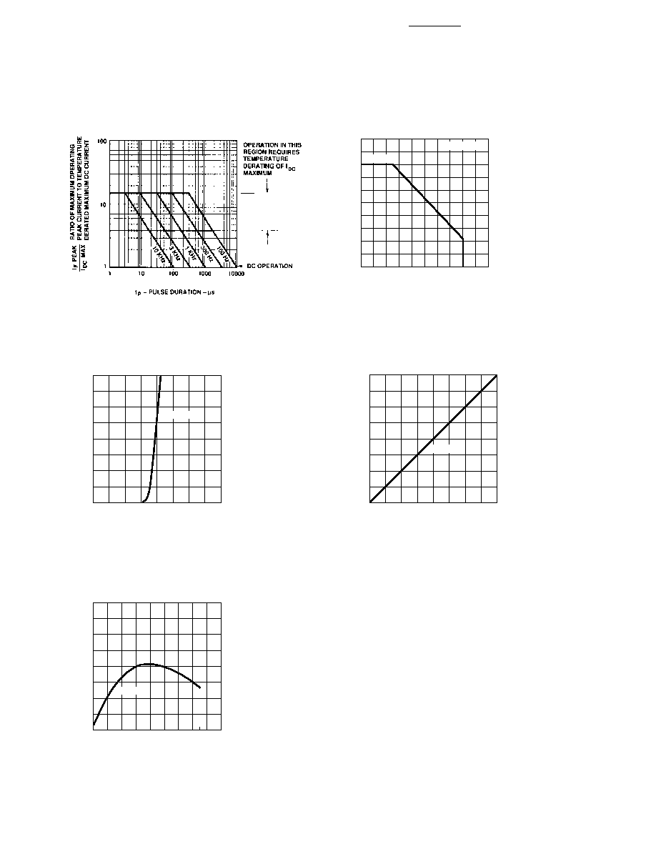
Figure 3. Forward Current vs. Forward Voltage.
Figure 2. Maximum Allowable DC Current vs.
Ambient Temperature.
Figure 4. Relative Luminous Intensity vs. DC
Forward Current.
Figure 5. Relative Efficiency (Luminous Intensity
per Unit Current) vs. Peak Current.
AlGaAs Red
Figure 1. Maximum Allowed Peak Current vs. Pulse
Duration ≠ AlGaAs Red.
I
DC
MAX. ≠ MAXIMUM DC CURRENT PER SEGMENT ≠ mA
20
0
T
A
≠ AMBIENT TEMPERATURE ≠ ∞C
30
90
120
50
30
70
50
AlGaAs RED
10
20
5
15
25
35
40
60
80
100 110
40
45
R
J-A
= 770∞C/W
I
F
≠
FORWARD CURRENT PER SEGMENT
≠
mA
0
0
V
F
≠ FORWARD VOLTAGE ≠ V
160
100
60
2.0
4.0
80
20
1.0
3.0
40
AlGaAs RED
0.5
1.5
2.5
3.5
120
140
RELATIVE LUMINOUS INTENSITY
(NORMALIZED TO 1 AT 20 mA)
0
0
I
F
≠ FORWARD CURRENT PER SEGMENT ≠ mA
2.00
1.50
1.25
0.75
0.25
20
40
1.75
1.00
0.50
10
30
5
15
25
35
AlGaAs RED
PEAK
≠
NORMALIZED RELATIVE EFFICIENCY
0.5
0.6
I
PEAK
≠ PEAK FORWARD CURRENT
PER SEGMENT ≠ mA
50.0
150.0
1.4
0.8
5.0
1.0
1.2
AlGaAs RED
8
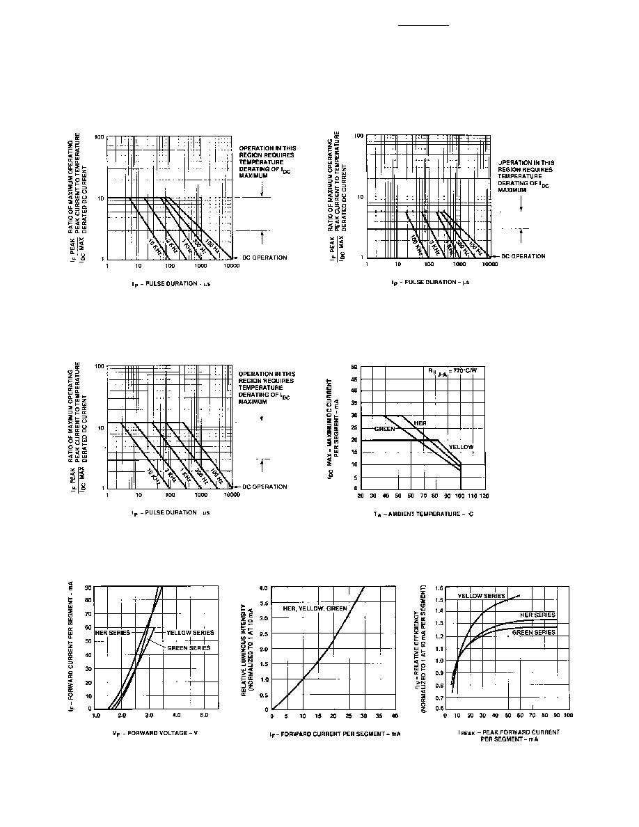
HER, Yellow, Green
Figure 6. Maximum Tolerable Peak Current vs.
Pulse Duration ≠ HER Series.
Figure 7. Maximum Tolerable Peak Current vs.
Pulse Duration ≠ Yellow Series.
Figure 8. Allowable Peak Current vs.
Pulse Duration ≠ Green Series.
Figure 9. Maximum Allowable DC Current vs.
Ambient Temperature.
Figure 11. Relative Luminous
Intensity vs. DC Forward Current.
Figure 10. Forward Current vs.
Forward Voltage.
Figure 12. Relative Luminous
Efficiency (Luminous Intensity per
Unit Current) vs. Peak Current.
9
HDSP-E15x
IV Bin Category
Min.
Max.
L
8.67
15.90
M
13.00
23.80
N
19.50
35.80
O
29.30
53.60
P
43.90
80.50
Intensity Bin Limits (mcd)
AlGaAs Red
HER
5082-761x
IV Bin Category
Min.
Max.
B
0.369
0.630
C
0.516
0.946
D
0.774
1.418
E
1.160
2.127
F
1.740
3.190
G
2.610
4.785
H
3.915
7.177
5082-765x
IV Bin Category
Min.
Max.
B
0.347
0.593
C
0.485
0.890
D
0.728
1.333
E
1.091
2.000
F
1.636
3.000
G
2.454
4.500
H
3.682
6.751
Yellow
5082-762x
IV Bin Category
Min.
Max.
B
0.229
0.387
C
0.317
0.582
D
0.476
0.872
E
0.714
1.311
F
1.073
1.967
G
1.609
2.950
H
2.413
4.425
5082-766x
IV Bin Category
Min.
Max.
C
0.297
0.543
D
0.445
0.817
E
0.669
1.225
F
1.003
1.838
G
1.504
2.758
H
2.256
4.137
HDSP-460x
IV Bin Category
Min.
Max.
G
1.03
1.88
H
1.54
2.82
I
2.31
4.23
J
3.46
6.34
K
5.18
9.50
L
7.78
14.26
Green
HDSP-360x
IV Bin Category
Min.
Max.
H
0.86
1.58
I
1.29
2.37
J
1.94
3.55
K
2.90
5.33
L
4.37
8.01
Contrast Enhancement
For information on contrast
enhancement, please see
Application Note 1015.
Soldering/Cleaning
For information on soldering
LEDs, please refer to Application
Note 1027.
Note:
All categories are established for classification of products. Products
may not be available in all categories. Please contact your Agilent
representatives for further clarification/information.
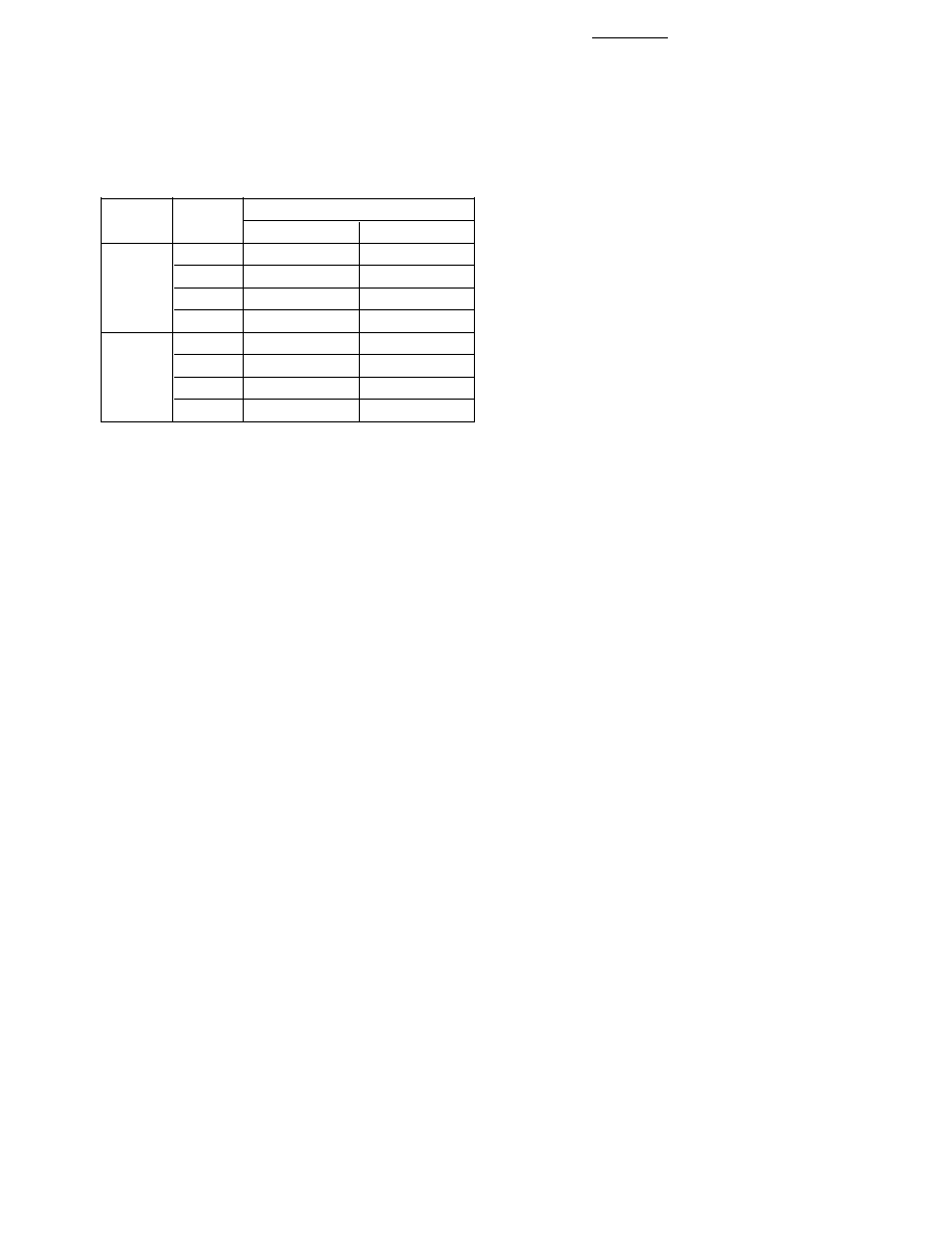
Dominant Wavelength (nm)
Color
Bin
Min.
Max.
Yellow
1
581.50
585.00
3
584.00
587.50
2
586.50
590.00
4
589.00
592.50
Green
2
573.00
577.00
3
570.00
574.00
4
567.00
571.00
5
564.00
568.00
Color Categories
10
www.agilent.com/semiconductors
For product information and a complete list of
distributors, please go to our web site.
For technical assistance call:
Americas/Canada: +1 (800) 235-0312 or
(916) 788-6763
Europe: +49 (0) 6441 92460
China: 10800 650 0017
Hong Kong: (+65) 6756 2394
India, Australia, New Zealand: (+65) 6755 1939
Japan: (+81 3) 3335-8152 (Domestic/Interna-
tional), or 0120-61-1280 (Domestic Only)
Korea: (+65) 6755 1989
Singapore, Malaysia, Vietnam, Thailand,
Philippines, Indonesia: (+65) 6755 2044
Taiwan: (+65) 6755 1843
Data subject to change.
Copyright © 2004 Agilent Technologies, Inc.
Obsoletes 5963-7394E
July 17, 2004
5988-3325EN