
10 mm (0.40 inch) Seven
Segment Displays
Technical Data
Features
∑ Industry Standard Size
∑ Industry Standard Pinout
7.6 mm (0.3 inch) DIP Single
15.24 mm (0.6 inch) DIP Dual
Leads on 2.54 mm
(0.1 inch) Centers
∑ Choice of Colors
AlGaAs Red, High Efficiency
Red, Orange, Yellow, Green
∑ Excellent Appearance
Evenly Lighted Segments
Mitered Corners on Segments
Gray Package Gives Optimum
Contrast
Black Surface and Color Tinted
Epoxy (HDSP-F161 only)
± 50∞ Viewing Angle
∑ Design Flexibility
Common Anode or
Common Cathode
Single and Dual Digits
Right Hand Decimal Point
± 1. Overflow Character
∑ Categorized for Luminous
Intensity
Yellow and Green Categorized
for Color
Use of Like Categories Yields a
Uniform Display
∑ High Light Output
∑ High Peak Current
∑ Excellent for Long Digit
String Multiplexing
HDSP-F15x Series
HDSP-F16x Series
HDSP-F20x Series
HDSP-F30x Series
HDSP-F40x Series
HDSP-F50x Series
HDSP-G00x Series
HDSP-G15x Series
HDSP-G20x Series
HDSP-G30x Series
HDSP-G40x Series
HDSP-G50x Series
∑ Intensity and Color
Selection Option
∑ Sunlight Viewable AlGaAs
AlGaAs
Red
[1]
HER
Orange
Yellow
Green
Package
HDSP-
HDSP-
HDSP-
HDSP-
HDSP-
Description
Drawing
F151
F201
F401
F301
F501
Common Anode Right Hand Decimal
A
F161
Common Anode Right Hand Decimal
A
F153
F203
F403
F303
F503
Common Cathode Right Hand Decimal
B
F157
F207
F407
F307
F507
Common Anode
± 1. Overflow
C
F158
F208
F408
F308
F508
Common Cathode
± 1. Overflow
D
G151
G201
G401
G301
G501
Two Digit Common Anode
Right Hand Decimal
E
G153
G203
G403
G303
G503
Two Digit Common Cathode
Right Hand Decimal
F
Devices
Note:
1. These displays are recommended for high ambient light operation. Please refer to the HDSP-F10X data sheet for low current
operation.

2
Description
The 10 mm (0.40 inch) LED
seven segment displays are
Agilent's most space-efficient
character size. They are designed
for viewing distances up to 4.5
metres (15 feet). These devices
use an industry standard size
package and pinout. The dual
numeric, single numeric, and
± 1.
overflow devices feature a right
hand decimal point. All devices
are available as either common
anode or common cathode.
Typical applications include
instruments, point of sale
terminals, and appliances.
Part Numbering System
5 0 8 2 - x xx x - x x x xx
HDSP - x xx x - x x x xx
Mechanical Options
[1]
00: No mechanical option
16: Special dimensional tolerances
Color Bin Options
[1,2]
0: No color bin limitation
Maximum Intensity Bin
[1,2]
0: No maximum intensity bin limitation
Minimum Intensity Bin
[1,2]
0: No minimum intensity bin limitation
Device Configuration/Color
[1]
1: Common Anode
3: Common Cathode
Device Specific Configuration
[1]
Refer to respective data sheet
Package
[1]
F: 10 mm (0.4 inch) Single Digit Seven Segment Display
G: 10 mm (0.4 inch) Dual Digit Seven Segment Display
Notes:
1. For codes not listed in the figure above, please refer to the respective data sheet or contact your nearest Agilent representative
for details.
2. Bin options refer to shippable bins for a part-number. Color and Intensity Bins are typically restricted to 1 bin per tube
(exceptions may apply). Please refer to respective data sheet for specific bin limit information.
3
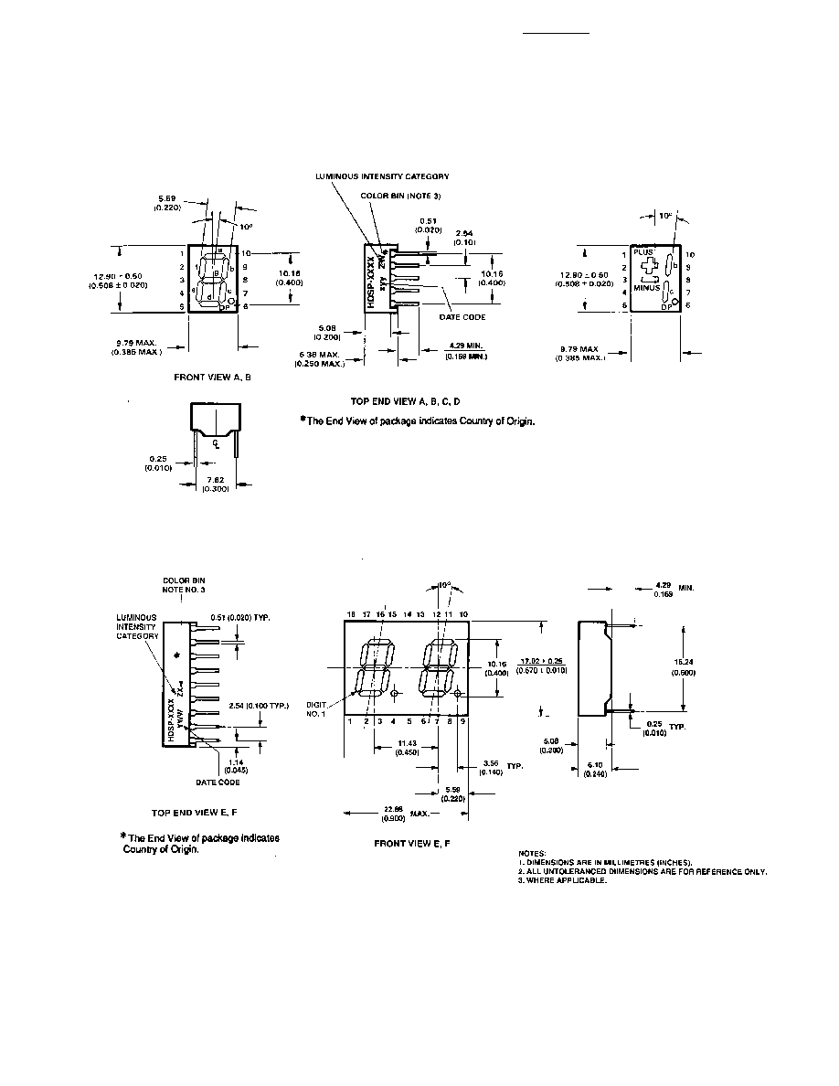
Package Dimensions
4
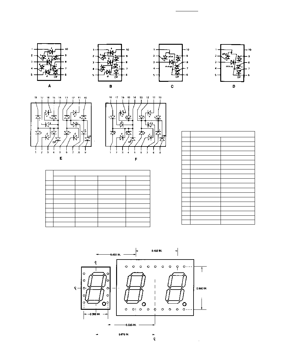
FUNCTION
PIN
E
F
1
E CATHODE NO. 1
E ANODE NO. 1
2
D CATHODE NO. 1
D ANODE NO. 1
3
C CATHODE NO. 1
C ANODE NO. 1
4
DP CATHODE NO. 1
DP ANODE NO. 1
5
E CATHODE NO. 2
E ANODE NO. 2
6
D CATHODE NO. 2
D ANODE NO. 2
7
G CATHODE NO. 2
G ANODE NO. 2
8
C CATHODE NO. 2
C ANODE NO. 2
9
CP CATHODE NO. 2
DP ANODE NO. 2
10
B CATHODE NO. 2
B ANODE NO. 2
11
A CATHODE NO. 2
A ANODE NO. 2
12
F CATHODE NO. 2
F ANODE NO. 2
13
DIGIT NO. 2 ANODE
DIGIT NO. 2 CATHODE
14
DIGIT NO. 1 ANODE
DIGIT NO. 1 CATHODE
15
B CATHODE NO. 1
B ANODE NO. 1
16
A CATHODE NO. 1
A ANODE NO. 1
17
G CATHODE NO. 1
G ANODE NO. 1
18
F CATHODE NO. 1
F ANODE NO. 1
FUNCTION
PIN
A
B
C
D
1
ANODE
[1]
CATHODE
[2]
ANODE
[1]
CATHODE
[2]
2
CATHODE f
ANODE f
CATHODE PLUS
ANODE PLUS
3
CATHODE
g
ANODE g
CATHODE MINUS
ANODE MINUS
4
CATHODE e
ANODE e
NC
NC
5
CATHODE d
ANODE d
NC
NC
6
ANODE
[1]
CATHODE
[2]
ANODE
[1]
CATHODE
[2]
7
CATHODE DP
ANODE DP
CATHODE DP
ANODE DP
8
CATHODE c
ANODE c
CATHODE c
ANODE c
9
CATHODE b
ANODE b
CATHODE b
ANODE b
10
CATHODE a
ANODE a
NC
NC
NOTES:
1. REDUNDANT ANODES
2. REDUNDANT CATHODES
Internal Circuit Diagram
HOLE PATTERN FOR PCB LAYOUT TO ACHIEVE UNIFORM 0.450 IN. DIGIT TO DIGIT PITCH. FOR HDSP-FXXX TO HDSP-GXXX.

5
Electrical/Optical Characteristics at T
A
= 25
∞
C
Notes:
1. See Figure 1 to establish pulsed conditions.
2. Derate above 46
∞C at 0.54 mA/∞C.
3. See Figure 6 to establish pulsed conditions.
4. Derate above 53
∞C at 0.45 mA/∞C.
5. See Figure 7 to establish pulsed conditions.
6. Derate above 81
∞C at 0.52 mA/∞C.
7. See Figure 8 to establish pulsed conditions.
8. Derate above 39
∞C at 0.37 mA/∞C.
9. For operation below -20
∞C, contact your local Agilent
components sales office or an authorized distributor.
Device
Series
Parameter
Symbol
Min.
Typ.
Max.
Units
Test Conditions
Luminous Intensity/Segment
[1, 2, 5]
I
V
7.5
15.0
mcd
I
F
= 20 mA
(Digit Average)
Forward Voltage/Segment or DP
V
F
1.8
2.2
V
I
F
= 20 mA
HDSP-
Peak Wavelength
PEAK
645
nm
F15x/
F16x/
Dominant Wavelength
[3]
d
637
nm
G15x
Reverse Voltage/Segment or DP
[4]
V
R
3.0
15
V
I
R
= 100
µA
Temperature Coefficient of
V
F
/
∞C
-2
mV/
∞C
V
F
/Segment or DP
Thermal Resistance LED
R
J-PIN
320
∞C/W/Seg
Junction-to-Pin
AlGaAs Red
Absolute Maximum Ratings
AlGaAs Red
HER/Orange
Yellow
Green
HDSP-
HDSP-
HDSP-
HDSP-
F15x/F16x
F20x/G20x/
F30x/G30x
F50x/G50x
Description
G15x Series
G40x Series
Series
Series
Units
Average Power per Segment or DP
96
105
80
105
mW
Peak Forward Current per
160
[1]
90
[3]
60
[5]
90
[7]
mA
Segment or DP
DC Forward Current per Segment
40
[2]
30
[4]
20
[6]
30
[8]
mA
or DP
Operating Temperature Range
≠20 to +100
[9]
≠40 to +100
∞C
Storage Temperature Range
≠55 to +100
∞C
Reverse Voltage per Segment or DP
3.0
V
Wavesoldering Temperature for
250
∞C
3 Seconds (1.59 mm [0.063 in.]
below body)