
Agilent ACMD-7401
Miniature PCS Band Duplexer
Data Sheet
Description
The ACMD-7401 is a miniaturized
duplexer designed using Agilent's
Film Bulk Acoustic Resonator
(FBAR) technology. The ACMD-
7401 is the first duplexer built
with Agilent's innovative
Microcap bonded-wafer chip
scale packaging technology. This
process allows the ultra small
filters to be assembled in a
molded chip-on-board (MCOB)
module that is less than 1.4 mm
high with a 5 x 5 mm footprint.
The ACMD-7401 enhances the
sensitivity and dynamic range of
CDMA receivers, providing more
than 50 dB attenuation of transmit-
ted signal at the receiver input, and
Features
∑ Miniature size: less than 1.4 mm
high, 5 x 5 mm footprint
∑ Rx Band: 1930 ≠ 1990 MHz typical
performance:
Rx Noise Blocking: 44 dB
Insertion Loss: 2.2 dB typical,
3.0 dB band edge
∑ Tx Band: 1850 ≠ 1910 MHz typical
performance:
Tx Interferer Blocking: 54 dB
Insertion Loss: 1.8 dB typical,
2.5 dB band edge
∑ 30 dBm Tx Power Handling
Applications
∑ Handsets or data terminals
operating in the US PCS frequency
band
more than 40 dB rejection of the
transmit-generated noise in the
receive band. Typical insertion loss
in the Tx channel is only 1.8 dB,
minimizing current drain from the
power amplifier. Typical insertion
loss in the Rx channel is 2.2 dB,
improving receiver sensitivity.
Agilent's thin-film Bulk Acoustic
Resonator (FBAR) technology
makes possible high-Q filters at a
fraction their usual size. The
excellent power handling of the
bulk-mode resonators supports
the high output powers needed in
PCS handsets, with virtually no
added distortion.

2
ACMD-7401 Electrical Specifications, Z
O
= 50
, T
C
[1]
as indicated
+25
∞C
[1,3]
+85
∞C
[1,2,3,4]
≠30
∞C
[1,2,3]
Symbol
Parameters
Units
Min
Typ
Max
Min
Typ
Max
Min
Typ
Max
Path from Antenna Port to Receiver Port
S23
Attenuation in Transmit Band
dB
50
54
--
50
52
--
50
52
--
(1850.6 ≠ 1909.4 MHz)
S23
Insertion Loss, lower band edge
dB
--
2.6
3.5
--
2.7
3.5
--
3.2
4.5
(1930.6≠ 1935 MHz)
S23
Insertion Loss, mid-band
dB
--
2.2
3.5
--
32.3
3.0
--
2.2
3.5
(1935≠ 1987 MHz)
S23
Insertion Loss, upper band edge
dB
--
2.8
3.5
--
2.8
3.8
--
2.7
3.5
(1987≠ 1989.4 MHz)
S23
Ripple in Receive Band
dB
--
1.5
2.6
--
1.5
3.0
--
2.0
3.0
S22
Rx Port Return Loss in Receive Band
dB
8.0
10
--
8.0
10
--
8.0
10
--
Path from Transmitter Port to Antenna Port
S31
Attenuation in Receive Band
dB
40
44
--
40
42
--
37
42
--
(1930.6 ≠ 1935 MHz)
S31
Attenuation in Receive Band
dB
40
42
--
40
42
--
40
42
--
(1935≠ 1989.4 MHz)
S31
Insertion Loss, lower band edge
dB
--
2.3
3.0
--
2.3
3.0
--
2.3
3.6
(1850.6≠ 1853 MHz)
S31
Insertion Loss, mid-band
dB
--
2.2
3.0
--
2.2
3.0
--
2.2
3.0
(1853≠ 1907 MHz)
S31
Insertion Loss, upper band edge
dB
--
1.6
3.0
--
2.4
3.8
--
1.2
3.0
(1907≠ 1909.4 MHz)
S31
Ripple in Transmit Band
dB
--
2.0
2.5
--
2.0
3.0
--
2.0
3.0
S11
Tx Port Return Loss in Transmit Band
dB
8.0
10
--
8.0
10
--
8.0
10
--
S33
Antenna Port Return Loss,
dB
8.0
10
--
8.0
10
--
8.0
10
--
Tx and Rx bands
S21
Tx-Rx Isolation, 1850.6 ≠ 1909.4 MHz
dB
50
54
--
50
54
--
50
54
--
(Transmit Band)
S21
Tx-Rx Isolation, 1930.6 ≠ 1935 MHz
dB
40
44
--
40
44
--
38
44
--
(Receive Band)
S21
Tx-Rx Isolation, 1935≠ 1989.4 MHz
dB
40
44
--
40
44
--
40
44
--
(Receive Band)
Notes:
1. T
C
is defined as case temperature, the temperature of the underside of the
duplexer where it makes contact with the circuit board. Port 1 = Tx,
Port 2 = Rx, Port 3 = Ant
2. Specifications are given at operating temperature limits and room
temperature. To estimate performance at some intermediate temperature,
use linear interpolation.
3. Specifications are guaranteed over the given temperature range, with the
input power to the Tx port equal to +29 dBm (or lower) over all Tx
frequencies. Upper transmit band edge maximum Insertion Loss at 85
∞C
is guaranteed to +26 dBm of input power. For higher input power, derate
maximum temperature as: Tmax = 95
∞C ≠ 25∞C * Pin (Watts). Input power
between +26 dBm and +30 dBm is safe, but the Insertion Loss at the
upper transmit band edge will degrade slightly.
4. High temperature specifications are guaranteed with thermal pads in
thermal contact with the motherboard. (See Figure 1.)
Thermal Pads ensure good
thermal contact to the motherboard.
Figure 1. Underside of the duplexer.
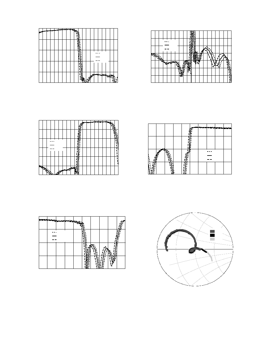
3
0
-10
-20
-30
-40
-50
S31 (Ant-Tx), (dB)
1.82
1.84
1.86
1.88
1.90
1.92
1.94
1.96
1.98
2.00
2.02
FREQUENCY (GHz)
Figure 2. Loss, Tx port to antenna port.
-30
∞C
25
∞C
85
∞C
-35
-40
-45
-50
-55
-60
-65
-70
S21 (Tx to Rx isolation), (dB)
Figure 3. Isolation (Tx to Rx ports).
-30
∞C
25
∞C
85
∞C
1.82
1.84
1.86
1.88
1.90
1.92
1.94
1.96
1.98
2.00
2.02
FREQUENCY (GHz)
0
-10
-20
-30
-40
-50
-60
S23 (Ant-Rx), (dB)
Figure 4. Loss, antenna port to Rx port.
-30
∞C
25
∞C
85
∞C
1.82
1.84
1.86
1.88
1.90
1.92
1.94
1.96
1.98
2.00
2.02
FREQUENCY (GHz)
0
-5
-10
-15
-20
S11 (Tx Return Loss), (dB)
1.82
1.84
1.86
1.88
1.90
1.92
1.94
1.96
1.98
2.00
2.02
FREQUENCY (GHz)
Figure 5. Return Loss, Tx port.
-30
∞C
25
∞C
85
∞C
0
-5
-10
-15
-20
S22 (Rx Return Loss), (dB)
1.82
1.84
1.86
1.88
1.90
1.92
1.94
1.96
1.98
2.00
2.02
FREQUENCY (GHz)
Figure 6. Return loss, Rx port.
-30
∞C
25
∞C
85
∞C
-30
∞C
25
∞C
85
∞C
Figure 7. Tx port impedance (8 dB circle).
freq (1.850 GHz to 1.909 GHz)
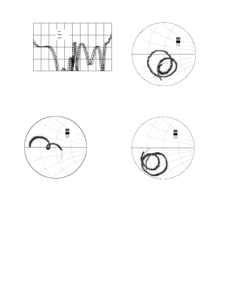
4
0
-5
-10
-15
-20
S33 (Ant Return Loss), (dB)
1.82
1.84
1.86
1.88
1.90
1.92
1.94
1.96
1.98
2.00
2.02
FREQUENCY (GHz)
Figure 8. Return loss, antenna port.
-30
∞C
25
∞C
85
∞C
-30
∞C
25
∞C
85
∞C
Figure 9. Rx port impedance (8 dB circle).
freq (1.930 GHz to 1.990 GHz)
-30
∞C
25
∞C
85
∞C
Figure 10. Antenna port impedance, Tx band (8 dB circle).
freq (1.850 GHz to 1.910 GHz)
-30
∞C
25
∞C
85
∞C
Figure 11. Antenna port impedance, Rx band (8 dB circle).
freq (1.930 GHz to 1.990 GHz)
5
Applications Information
Agilent's ACMD-7401 duplexers
provide high RF performance in
a very small package. However, in
order to achieve all the perfor-
mance available from the
duplexer, care must be taken in
the design of the board onto
which it is mounted. The purpose
of this information is to provide
Agilent's recommendations on
the design of that board (called
the motherboard in this note).
Areas where care in design must
be observed are thermal ground,
RF ground, in/out connection
design, and solder mask/solder
stencil design. These four design
areas, which are sometimes
interrelated, will be considered
one at a time below.
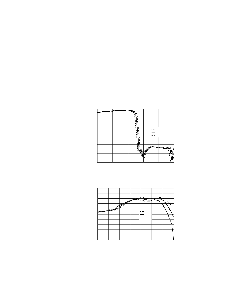
Thermal Ground
FBAR resonators have a negative
temperature coefficient of
frequency -- as temperature goes
up, the frequency response of the
filter shifts down in frequency.
See Figure 12. Typical coeffi-
cients are 57 KHz/
∞C for the Tx
filter and 40 KHz/
∞C for the Rx
filter. In Figure 13, the same data
are presented with the scale
narrowed down to the upper end
of the Tx band. Note that all
these data are taken at low input
power levels (+10 dBm).
When input power is +29 dBm,
heating in the Tx filter due to RF
losses causes the filter membranes
to heat up beyond 85
∞C. This, in
turn, causes the filter response to
shift further left (down in fre-
quency), resulting in increased
insertion loss at the high end of
the Tx band (1910 MHz). Agilent
Technologies takes this into
account in the manufacture and
final test of the duplexer -- all
specifications for insertion loss
(and other parameters) will be met
at the specified input power level
and motherboard temperature.
Note that high power/high tem-
perature testing done at Agilent is
performed with the duplexer
soldered down to a test board
having a very good heat sink.
The motherboard must be de-
signed to remove heat from the
duplexer with the lowest possible
thermal resistance. Mount the
duplexer on a large surface of
1
/
2
ounce copper ground plane
(as shown in Figure 14), to enable
the heat to be removed in all
directions. Via holes, necessary
for RF grounding, should be filled
with copper plating to further
remove heat from the duplexer's
Tx filter and dump it into a
second ground plane located in a
lower layer of the motherboard.
FBAR duplexers have extremely
low thermal mass and must be
properly heat sunk, as well as
isolated from external sources of
heat (such as a nearby power
amplifier). Failure to provide an
adequate thermal design to cool
0
-10
-20
-30
-40
-50
-60
S31 (Ant-Rx), (dB)
1.82
1.86
1.90
1.94
1.98
2.02
FREQUENCY (GHz)
Figure 12. Tx Filter Response with Temperature.
-30
∞C
25
∞C
85
∞C
0.0
-0.5
-1.0
-1.5
-2.0
-2.5
-3.0
-3.5
-4.0
-4.5
-5.0
S31 (TX to Ant Loss), (dB)
1.845
1.855
1.865
1.875
1.885
1.895
1.905
1.915
FREQUENCY (GHz)
Figure 13. Tx Filter Response with Temperature (expanded).
-30
∞C
25
∞C
85
∞C