 | –≠–ª–µ–∫—Ç—Ä–æ–Ω–Ω—ã–π –∫–æ–º–ø–æ–Ω–µ–Ω—Ç: HBCR-1697 | –°–∫–∞—á–∞—Ç—å:  PDF PDF  ZIP ZIP |
4-37
5965-5950E
H
Features
∑ Supports Five Industry
Standard Bar Code
Symbologies
∑ Automatic Code Recognition
∑ Choice of Parallel or Full
Duplex Serial ASCII
Interface
∑ Programmable via Escape
Sequences or Pin Strapping
∑ CMOS
∑ Through Hole and Surface
Mount Packages
∑ Audio and Visual Feedback
Control
Description
The Hewlett-Packard Single Chip
Bar Code Decoder IC offers
flexible bar code decoding that is
designed to give OEMs the ability
to address a growing number of
industry segments and applica-
tions. Flexibility is made possible
through firmware that allows the
IC to automatically recognize and
decode the most popular bar
code symbologies. User imple-
mentation is easy since only a few
supporting components are
required.
The HBCR-1610 series decodes
the most popular bar code
symbologies used in applications
in government, retail, industrial
and medical markets. The IC
automatically discriminates and
decodes the following
symbologies:
∑ Code 39 (Standard or
Extended)
∑ Interleaved 2 of 5
∑ UPC A, E0, E1
∑ EAN/JAN 8, 13
∑ Codabar
∑ Code 128
All bar codes may be scanned
bidirectionally except for UPC/
EAN/JAN bar codes with supple-
mental digits, which must be
scanned so that the supplemental
digits are scanned last.
Scanner Input
The HBCR-1610 decode ICs are
designed to accept input from
hand held digital scanners and
slot readers. The maximum scan
speed is 30 ips (73 cm/s).
Data Communications
The serial port supports a variety
of baud rates, parity, and stop
bits as described in Table 5. The
IC has a "Single Read Mode"
which allows the application
program to stop data input until a
"Next Read" command has been
received. This allows the host
computer to process data
transmissions before enabling
subsequent reads. Control of data
transmission is available using
the standard XON/XOFF (
D1/ D3
)
handshake.
The parallel port is accomplished
via an external 74HCT646 (octal
bus transceiver) or two
74HCT574s (octal latches).
There are handshake lines for
both data and commands.
Feedback Features
Both audible and visual feedback
are possible with the HBCR-1610
series. In both cases, the
feedback outputs from the IC
should be buffered before driving
the transducer. An LED or beeper
connected to the IC is either
controlled directly by the IC, with
signals generated by successful
decodes, or controlled by the
host system. The tone of the
beeper can be configured to one
of 16 tones, or can be silenced.
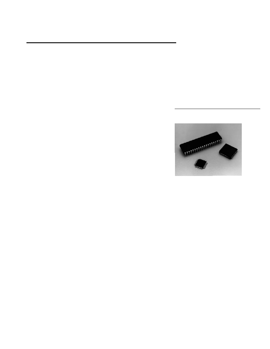
Single Chip Bar Code Decode IC
Technical Data
HBCR-1610
HBCR-1611
HBCR-1612

4-38
Power Requirements
The decoder IC is operated from
a +5 volt DC power supply. The
maximum current draw is 24 mA.
The maximum power supply
ripple voltage should be less than
100 mV, peak-to-peak.
Idle Mode
The IC automatically reduces
power consumption whenever
there is no scanning or decoding
activity, or when there is no
activity on the I/O port. See
Table 4.
Manual
The HBCR-1610 Series Users
Manual (HBCR-1697) covers the
following topics:
∑ Specifications and Timing
Diagrams
∑ Pin Definitions and Schematics
∑ General Scanning Tips
∑ Configuration and Operation
∑ Escape Sequence Programming
∑ Data Output Formats
∑ Sample Bar Codes
∑ I/O and Pacing Characteristics
IC Configuration
The default configuration is set
when the IC powers up or when a
Hard Reset command is received.
Default configuration of many of
the options is dependent on the
logic states of IC pins, as shown
in Table 5. A complete descrip-
tion of the pins and all possible
configurations is in the Users
Manual. More complete and
flexible configuration is achieved
using escape sequence
commands.
There are two pins that cause
significant changes in the IC
operation.
Table 1. Recommended Operating Conditions
Parameter
Symbol
Minimum
Maximum
Units Notes
Supply Voltage
V
CC
4.5
5.5
V
1
Ambient
T
A
0
+70
∞
C
Temperature
Oscillator
F
OSC
DC
16.000
MHz
2
Frequency
Notes:
1. Maximum power supply ripple of 100 mV peak-to-peak.
2. The IC can use either an 11.059 or a 16.000 MHz crystal or ceramic resonator. The
FRQ pin selects the frequency that matches the oscillator.
Table 2. Absolute Maximum Ratings
Parameter
Symbol
Minimum
Maximum
Units Notes
Storage
T
S
-65
+150
∞
C
Temperature
Supply Voltage
V
CC
-0.5
+7.0
V
Pin Voltage
V
IN
-0.5
V
CC
+ 0.5
V
3
Note:
3. Voltage on any pin with respect to ground.
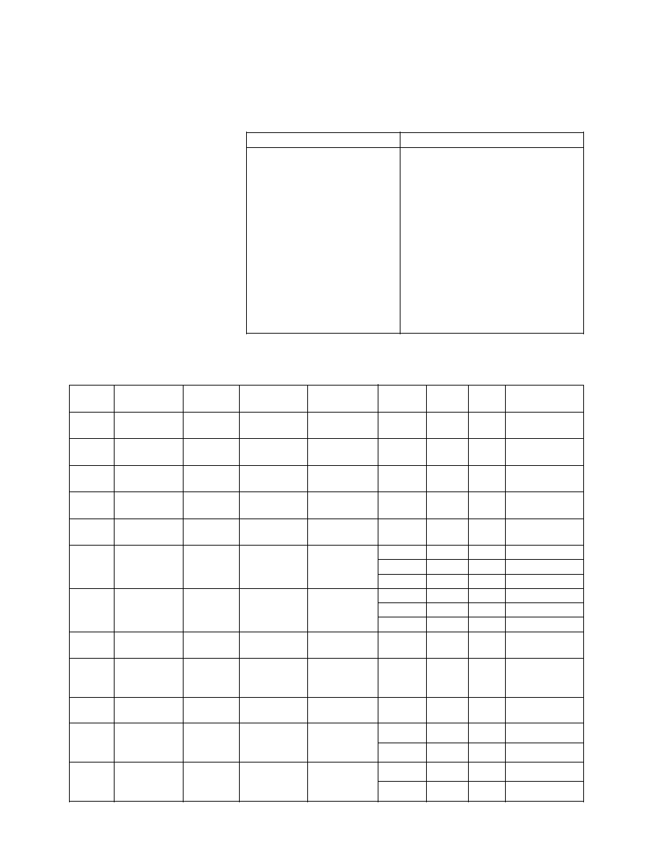
Table 3. Ordering Information
Part Number
Description
HBCR-1610
CMOS, 40 pin DIP, bulk shipment, no manual
HBCR-1611
CMOS, 44 pin PLCC, bulk shipment, no manual
HBCR-1612
CMOS, 40 pin QFP, bulk shipment, no manual
HBCR-1697
HBCR-1610 Series Users Manual
Option A01
IC individually bagged, no manual
Option B01
IC individually boxed with manual and data sheet
FRQ Pin
The
FRQ
pin is used to tell the IC
what frequency oscillator is
attached to the IC. Using the
higher frequency allows greater
maximum scan speeds, but
causes the IC to draw slightly
more supply current. If the state
of the
FRQ
pin does not match
the actual oscillator, beeper
tones, LED flash length, parallel
port timing, and serial port baud
rates are adversely affected.
FRQ
Oscillator Frequency
0
16.000 MHz
1
11.059 MHz
IOM Pin
The
IOM
pin selects between the
serial and parallel I/O mode of the
IC. Depending on the state of the
IOM
pin, definitions of several
configuration pins change or
move to new positions.
IOM
I/O Mode
0
Parallel
1
Serial
4-39
Table 4. DC Characteristics
HBCR-1610, 1611, 1612 (T
A
= 0
∞
C to +70
∞
C, V
CC
= 4.5 V to 5.5 V, V
SS
= 0 V)
Test
Symbol
Parameter
1610 Pins
1611 Pins
1612 Pins
Min.
Max.
Units
Conditions
V
IL
Input Low
all
all
all
-0.5
0.2 V
CC
V
Voltage
- 0.1
V
IH
Input High
except
except
except
0.2 V
CC
V
CC
V
Voltage
9, 19
10, 21
4, 15
+ 0.9
+ 0.5
V
IH1
Input High
9, 19
10, 21
4, 15
0.7 V
CC
V
CC
V
Voltage
+ 0.5
V
OL
Output Low
1-8, 10-17,
2-9, 11,
1-3, 5, 7-13
0.45
V
I
OL
= 1.6 mA
Voltage
21-28
13-19, 24-31 18-25, 40, 44
V
OL1
Output Low
32-39
36-43
30-37
0.45
V
I
OL
= 3.2 mA
Voltage
V
OH
Output High 1-8, 10-17,
2-9, 11,
1-3, 5, 7-13
2.4
V
I
OH
= -60
µ
A
0.75 V
CC
V
I
OH
= -25
µ
A
0.9 V
CC
V
I
OH
= -10
µ
A
V
OH1
Output High
32-39
36-43
30-37
2.4
V
I
OH
= -400
µ
A
0.75 V
CC
V
I
OH
= -150
µ
A
0.9 V
CC
V
I
OH
= -40
µ
A
I
IL
Input Low
1-8, 10-17,
2-9, 11,
1-3, 5, 7-13,
-50
µ
A
V
IN
= 0.45 V
Current
21-28
13-19, 24-31 18-25, 40-44
I
LI
Input
32-39
36-43
30-37
±
10
µ
A
V
SS
V
IN
V
CC
Leakage
Current
R
RST
Pulldown
9
10
4
50
150
K
Resistor
I
CC
40
44
38
18
mA
Scanning
4
mA
Idle
I
CC
40
44
38
24
mA
Scanning
6
mA
Idle
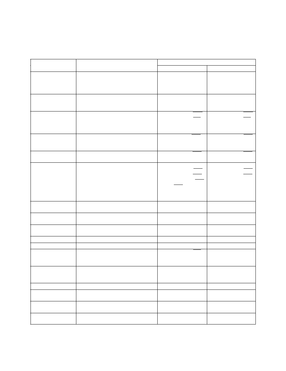
Table 7. Escape Sequences
Escape Sequence
Function
E
C - y <n> b
Good Read Beep Tone
E
C - y <n> d
Serial Intercharacter Delay
E
C E
Hard Reset
E
C - y <n> f
Bar Code Symbology Selection
E
C - y <n> g
Check Character Options
E
C - y <n> h
Decoding Options
E
C - y <n> j
Single Read Mode
E
C - y <n> k
Single Read Control
E
C - y <n> l
LED Control
E
C - y <n> m
Interleaved 2 of 5 Length
E
C - y <n> O <n characters>
Trailer Selection
E
C - y <n> q
Code ID Characters
E
C - y <n> s
Status Request
E
C - y <n> t
Sound Tone
E
C - y <n> w
Scanner Enable
Escape Sequences
The following set of escape
sequences is used to control the
IC and change its default configu-
ration. Note that all configuration
changes will be lost after a Hard
Reset, or after power up. Detailed
information on how to formulate
and use escape sequences is
given in the Users Manual.
Voltage
21-28
13-19, 24-31 18-25, 40-44
Voltage
Supply
Current
11.059 MHz
Supply
Current
16.000 MHz
4-40
Table 5. Summary of Features and Configurations ≠ HBCR-1610 Series
Default Setting
Feature
Function or Value
Serial Mode
Parallel Mode
Bar Code
When a symbology is enabled, bar
Depends on pins:
Symbology
codes of that type can be read,
C39
,
I25
,
UPC
All codes enabled
assuming other decoding options are
CDB
and
C28
.
satisfied.
Interleaved 2 of 5
Length variable from 4 to 32, or
Variable, 4-32
Variable, 4-32
Label Length
specific lengths from 2 to 32, or 6
or 14 only
Check Character
For Code 39
Depends on pin
C3C
Depends on pin
C3C
Verification
For Interleaved 2 of 5
Depends on pin
I2C
Depends on pin
I2C
For Code 128
Enabled
Enabled
For UPC/EAN
Enabled
Enabled
Check Character
For Code 39 and Interleaved 2 of 5
Depends on pin
CST
Depends on pin
CST
Transmission
For UPC/EAN
Enabled
Enabled
For Code 128
Enabled
Enabled
Extended Code 39
Converts paired Code 39 data
Depends on pin
EX3
Depends on pin
EX3
Enable
characters to Full ASCII characters
UPC/EAN
UPC vs. UPC/EAN
UPC/EAN
UPC/EAN
Decoding Options
UPC E expansion to UPC A
Depends on pin
UEE
Depends on pin
UEE
UPC E Version 1 autodiscrimination
Depends on pin
UE1
Depends on pin
UE1
UPC/EAN supplemental digits
Depends on pins
US2
Disabled
and
US5
UPC/EAN check digit
Transmitted
Transmitted
UPC/EAN output format
Standard
Standard
Codabar Start/
Transmits or suppresses Codabar
Depends on pin
CSS
Depends on pin
CSS
Stop Transmission
start/stop characters
Baud Rates
1200, 2400, 4800, 9600
Depends on pins
BR0
≠
and
BR1
Parity
0s, 1s, even, odd
Depends on pins
PT0
0s
and
PT1
Stop Bits
1 or 2
Depends on pin
STB
≠
XON/XOFF Pacing
Controls data flow on either port
Enabled
Enabled
Transmitted
Controls 10 millisecond intercharacter
Depends on pin
ICD
≠
Character Delay
delay on the serial port
Enable
Trailer Selection
String of characters appended
CR
,
CR
LF
,
HT
, or none
C
R
to the decoded message (4 maximum)
Depends on pins
TR0
and
TR1
Single Read Mode
Controls when labels can be read
Disabled
Disabled
Code ID Character
Controls the transmission of the Code
Disabled
Disabled
Enable
ID characters before decoded data
Good Read Beep
Controls the tone sounded when
High or low pitch
High or low pitch
Tone Selection
a bar code label is read
Depends on pin
GRB
Depends on pin
GRB
LED Control
Controls LED function: flash or
Auto Flash Mode
Auto Flash Mode
turn off after a label is read
Not configurable.

4-41
C39
I25
UPC
CDB
C28
U2S
U5S
CSS
BR0
BR1
STB
EX3
C3C
I2C
CST
GRB
ICD
UEE
UE1
FRQ
PT0
PT1
TR0
TR1
LED
SDI
XTAL 1
XTAL 2
VCC
EA
IOM
RST
BPR
TxD
RxD
RTS
CTS
GND
T2OUT
R2IN
T1OUT
R1IN
T2IN
R2OUT
T1IN
R1OUT
C1+
C1-
C2+
C2-
V+
V-
VCC
GND
TxD
RxD
RTS
CTS
+5 V
0 V
+5 V
C4
15
6
16
2
13
14
8
7
12
11
9
10
1
3
4
5
C1
C2
MAX232
LT1081 or
LT1181
SERIAL LEVEL
CONVERTER
+5 V
+5 V
47 K
+5 V
SDI
10 K
2N5088
150
8 x 10 K
+5 V
+5 V
500
10
10 K
10 µF
1N4148
1N4148
+5 V
PIEZO
BEEPER
0.047 µF
10
mH
HBCR-161X
NOTES:
1. USE THE CORRECT CAPACITOR FOR
EITHER A CRYSTAL OR A CERAMIC
RESONATOR. SEE USERS MANUAL, PAGE 2-16.
2. SEE THE PIN DIAGRAMS FOR THE PINOUT
OF THE DECODE IC. PIN NUMBERS VARY
WITH PACKAGE.
3. VOLUME OF THE BEEPER CIRCUIT IS
ADJUSTABLE BY VARYING THE VALUE
OF THE 500
POT.
4. THE EIGHT PULL UP RESISTORS SHOWN
IN THE SCHEMATIC ARE ONLY NEEDED
IF A DIP SWITCH IS USED. IF THE PINS
ARE STRAPPED DIRECTLY TO GROUND
OR VCC, THE RESISTORS ARE NOT NEEDED.
5. THE LOGIC LEVELS OF THE SDI SCANNER
INPUT IS AS FOLLOWS: BLACK = HIGH,
WHITE = LOW.
2N2907
C3
Table 6. Summary of Commands ≠ HBCR-1610 Series
Feature
Description
Scanner Enable
When enabled, scans from a wand or a slot reader are decoded; otherwise, they
are ignored.
Hard Reset
Resets the IC as though it were just powered up.
Self Test Failure
An error message is transmitted over the serial port at 9600 baud at power up if the
Message
IC self test fails.
Status Request
Returns the version number of the software.
Sound Tone
Causes the IC to sound a tone of the selected pitch for 120 milliseconds.
Stand Alone Decoder
(Serial Mode)