 | –≠–ª–µ–∫—Ç—Ä–æ–Ω–Ω—ã–π –∫–æ–º–ø–æ–Ω–µ–Ω—Ç: HCPL47XX | –°–∫–∞—á–∞—Ç—å:  PDF PDF  ZIP ZIP |

NC
ANODE
CATHODE
NC
VCC
VB
VO
GND
HCPL-4701/070A
VO2
VO1
VCC
GND
ANODE 1
CATHODE 1
CATHODE 2
ANODE 2
7
5
6
8
2
3
4
1
TRUTH TABLE
LED
ON
OFF
VO
LOW
HIGH
7
5
6
8
2
3
4
1
HCPL-4731/073A
Very Low Power Consumption
High Gain Optocouplers
Technical Data
Applications
∑ Battery Operated
Applications
∑ ISDN Telephone Interface
∑ Ground Isolation between
Logic Families ≠ TTL,
LSTTL, CMOS, HCMOS,
HL-CMOS, LV-HCMOS
∑ Low Input Current Line
Receiver
Features
∑ Ultra Low Input Current
Capability - 40
µ
A
∑ Specified for 3 V Operation
Typical Power Consumption:
<1 mW
Input Power: <50
µ
W
Output Power: <500
µ
W
∑ Will Operate with V
CC
as
Low as 1.6 V
∑ High Current Transfer
Ratio ≠ 3500% at I
F
= 40
µ
A
∑ TTL and CMOS Compatible
Output
∑ Specified AC and DC
Performance over
Temperature: 0
∞
C to 70
∞
C
∑ Safety Approval
UL Recognized - 2500 V rms
for 1 Minute and
5000 V rms* for 1 minute per
UL1577
CSA Approved
VDE 0884 Approved with
V
IORM
= 630 V
peak
(Option 060) for HCPL-4701
∑ 8-Pin Product Compatible
with 6N138/6N139 and
HCPL-2730/HCPL-2731
∑ Available in 8-Pin DIP and
SOIC-8 Footprint
∑ Through Hole and Surface
Mount Assembly Available
∑ EIA RS-232C Line Receiver
∑ Telephone Ring Detector
∑ AC Line Voltage Status
Indicator - Low Input Power
Dissipation
∑ Low Power Systems ≠
Ground Isolation
∑ Portable System I/O
Interface
HCPL-4701
HCPL-4731
HCPL-070A
HCPL-073A
CAUTION: It is advised that normal static precautions be taken in handling and assembly of this component to
prevent damage and/or degradation which may be induced by ESD.
Functional Diagram
*5000 V rms/1 Minute rating is for Option 020 (HCPL-4701 and HCPL-4731) products only.
A 0.1
µ
F bypass capacitor connected between pins 8 and 5 is recommended.

2
Description
These devices are very low power
consumption, high gain single
and dual channel optocouplers.
The HCPL-4701 represents the
single channel 8-Pin DIP configu-
ration and is pin compatible with
the industry standard 6N139. The
HCPL-4731 represents the dual
channel 8-Pin DIP configuration
and is pin compatible with the
popular standard HCPL-2731.
The HCPL-070A and HCPL-073A
are the equivalent single and dual
channel products in an SO-8
footprint. Each channel can be
driven with an input current as
low as 40
µ
A and has a typical
current transfer ratio of 3500%.
These high gain couplers use an
AlGaAs LED and an integrated
high gain photodetector to
provide an extremely high
current transfer ratio between
input and output. Separate pins
for the photodiode and output
stage results in TTL compatible
saturation voltages and high
speed operation. Where desired,
the V
CC
and V
O
terminals may be
tied together to achieve conven-
tional Darlington operation
(single channel package only).
These devices are designed for
use in CMOS, LSTTL or other low
power applications. They are
especially well suited for ISDN
telephone interface and battery
operated applications due to the
low power consumption. A 700%
minimum current transfer ratio is
guaranteed from 0
∞
C to 70
∞
C
operating temperature range at
40
µ
A of LED current and
V
CC
3 V.
The SO-8 does not require
"through holes" in a PCB. This
package occupies approximately
one-third the footprint area of the
standard dual-in-line package.
The lead profile is designed to be
compatible with standard surface
mount processes.
Selection Guide
Widebody
8-Pin DIP
Package
Hermetic
(300 Mil)
Small Outline SO-8
(400 mil)
Single and
Dual
Single
Dual
Minimum
Absolute
Dual
Single
Channel
Channel
Channel
Single
Input ON
Maxi-
Channel
Channel
Package
Package
Package
Channel
Current
Minimum
mum
Packages
Package
HCPL-
HCPL-
HCPL-
Package
(I
F
)
CTR
V
CC
HCPL-
6N139
[1]
2731
[1]
0701
[1]
0731
[1]
HCNW139
[1]
0.5 mA
400%
18 V
6N138
[1]
2730
[1]
0700
[1]
0730
[1]
HCNW138
[1]
1.6 mA
300%
7 V
HCPL-4701
4731
070A
0730A
40
µ
A
800%
18 V
0.5 mA
300%
20 V
5701
[1]
5700
[1]
5731
[1]
5730
[1]
Notes:
1. Technical data are on separate Agilent publication.
Ordering Information
Specify Part Number followed by Option Number (if desired).
Example:
HCPL-4701#XXX
020 = 5000 V rms/1 minute UL Rating Option.**
060 = VDE 0884 V
IORM
= 630 V peak Option
300 = Gull Wing Surface Mount Option.*
500 = Tape and Reel Packaging Option.
*Gull wing surface mount option applies to through hole parts only.
**For HCPL-4701 and HCPL-4731 (8-Pin DIP products) only.
For HCPL-4701 only. Combination of Option 020 and Option 060 is not available.
Option data sheets available. Contact your Agilent sales representative or authorized distributor for
information.

3
IF2
6
5
GND
3
4
VO2
VF2
IO2
+
≠
IF1
8
7
V
CC
1
2
V
O1
ICC
V
F1
IO1
≠
+
SHIELD
USE OF A 0.1 µF BYPASS CAPACITOR CONNECTED
BETWEEN PINS 5 AND 8 IS RECOMMENDED (SEE NOTE 8)
Schematic
HCPL-4701 and HCPL-070A
HCPL-4731 and HCPL-073A
IF
8
VCC
2
3
ICC
VF
ANODE
CATHODE
+
≠
VB
IB
6
5
GND
VO
IO
7
SHIELD
4
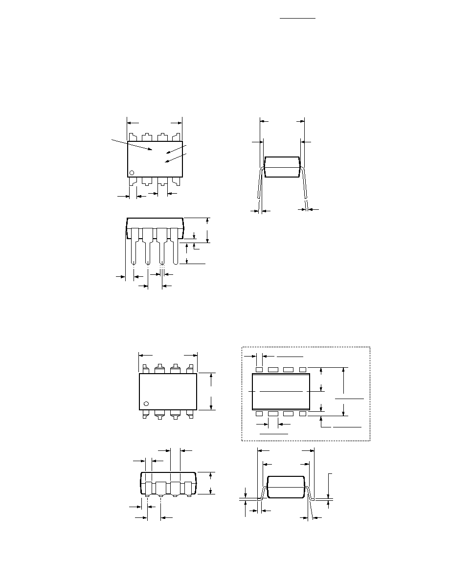
Package Outline Drawings
8-Pin DIP Package (HCPL-4701, HCPL-4731)
8-Pin DIP Package with Gull Wing Surface Mount Option 300 (HCPL-4701, HCPL-4731)
0.635 ± 0.25
(0.025 ± 0.010)
12∞ NOM.
9.65 ± 0.25
(0.380 ± 0.010)
0.635 ± 0.130
(0.025 ± 0.005)
7.62 ± 0.25
(0.300 ± 0.010)
5
6
7
8
4
3
2
1
9.65 ± 0.25
(0.380 ± 0.010)
6.350 ± 0.25
(0.250 ± 0.010)
1.016 (0.040)
1.194 (0.047)
1.194 (0.047)
1.778 (0.070)
9.398 (0.370)
9.906 (0.390)
4.826
(0.190)
TYP.
0.381 (0.015)
0.635 (0.025)
PAD LOCATION (FOR REFERENCE ONLY)
1.080 ± 0.320
(0.043 ± 0.013)
4.19
(0.165)
MAX.
1.780
(0.070)
MAX.
1.19
(0.047)
MAX.
2.54
(0.100)
BSC
DIMENSIONS IN MILLIMETERS (INCHES).
LEAD COPLANARITY = 0.10 mm (0.004 INCHES).
0.254
+ 0.076
- 0.051
(0.010
+ 0.003)
- 0.002)
9.65 ± 0.25
(0.380 ± 0.010)
1.78 (0.070) MAX.
1.19 (0.047) MAX.
A XXXXZ
YYWW
DATE CODE
1.080 ± 0.320
(0.043 ± 0.013)
2.54 ± 0.25
(0.100 ± 0.010)
0.51 (0.020) MIN.
0.65 (0.025) MAX.
4.70 (0.185) MAX.
2.92 (0.115) MIN.
DIMENSIONS IN MILLIMETERS AND (INCHES).
5
6
7
8
4
3
2
1
5∞ TYP.
OPTION CODE*
0.254
+ 0.076
- 0.051
(0.010
+ 0.003)
- 0.002)
7.62 ± 0.25
(0.300 ± 0.010)
6.35 ± 0.25
(0.250 ± 0.010)
TYPE NUMBER
*MARKING CODE LETTER FOR OPTION NUMBERS
"L" = OPTION 020
"V" = OPTION 060
OPTION NUMBERS 300 AND 500 NOT MARKED.
5
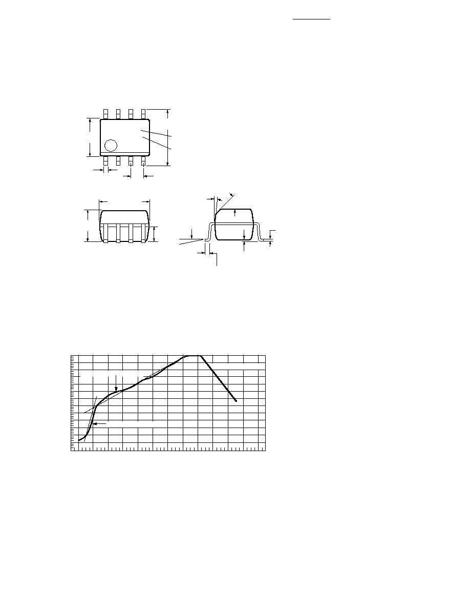
Small-Outline SO-8 Package (HCPL-070A, HCPL-073A)
240
T = 115∞C, 0.3∞C/SEC
0
T = 100∞C, 1.5∞C/SEC
T = 145∞C, 1∞C/SEC
TIME ≠ MINUTES
TEMPERATURE ≠ ∞C
220
200
180
160
140
120
100
80
60
40
20
0
260
1
2
3
4
5
6
7
8
9
10
11
12
Figure 1. Solder Reflow Thermal Profile (HCPL-070A, HCPL-073A, and Gull Wing
Surface Mount Option 300 Parts).
Note: Use of nonchlorine activated fluxes is highly recommended.
Solder Reflow Temperature Profile
XXX
YWW
8
7
6
5
4
3
2
1
5.994 ± 0.203
(0.236 ± 0.008)
3.937 ± 0.127
(0.155 ± 0.005)
0.406 ± 0.076
(0.016 ± 0.003)
1.270
(0.050)
BSG
5.080 ± 0.127
(0.200 ± 0.005)
3.175 ± 0.127
(0.125 ± 0.005)
1.524
(0.060)
45∞ X
0.432
(0.017)
0.228 ± 0.025
(0.009 ± 0.001)
TYPE NUMBER
(LAST 3 DIGITS)
DATE CODE
0.305
(0.012)
MIN.
TOTAL PACKAGE LENGTH (INCLUSIVE OF MOLD FLASH)
5.207 ± 0.254 (0.205 ± 0.010)
DIMENSIONS IN MILLIMETERS (INCHES).
LEAD COPLANARITY = 0.10 mm (0.004 INCHES) MAX.
0.203 ± 0.102
(0.008 ± 0.004)
7∞
PIN ONE
0 ~ 7∞
*
*