DATASHEET SEARCH SITE | WWW.ALLDATASHEET.COM
Agilent HCPL-7860/HCPL-786J
Optically Isolated
Sigma-Delta (
-
-
-
-
-) Modulator
Data Sheet
Features
··
··
· 12-bit Linearity
··
··
· 200 ns Conversion Time (Pre-
Trigger Mode 2 with HCPL-0872)
··
··
· 12-bit Effective Resolution with 5
µµ
µµ
µs Signal Delay (14-bit with 102
µµ
µµ
µs) (with HCPL-0872)
··
··
· Fast 3 µµµµµs Over-Range Detection
(with HCPL-0872)
··
··
· ± 200 mV Input Range with Single
5 V Supply
··
··
· 1% Internal Reference Voltage
Matching
··
··
· Offset Calibration (with HCPL-
0872)
··
··
· -40°C to +85°C Operating
Temperature Range
··
··
· 15 kV/µµµµµs Isolation Transient
Immunity
··
··
· Safety Approval: UL 1577, CSA
and IEC/EN/DIN EN 60747-5-2
Applications
··
··
· Motor Phase and Rail Current
Sensing
··
··
· Data Acquisition Systems
··
··
· Industrial Process Control
··
··
· Inverter Current Sensing
··
··
· General Purpose Current Sensing
and Monitoring
Description
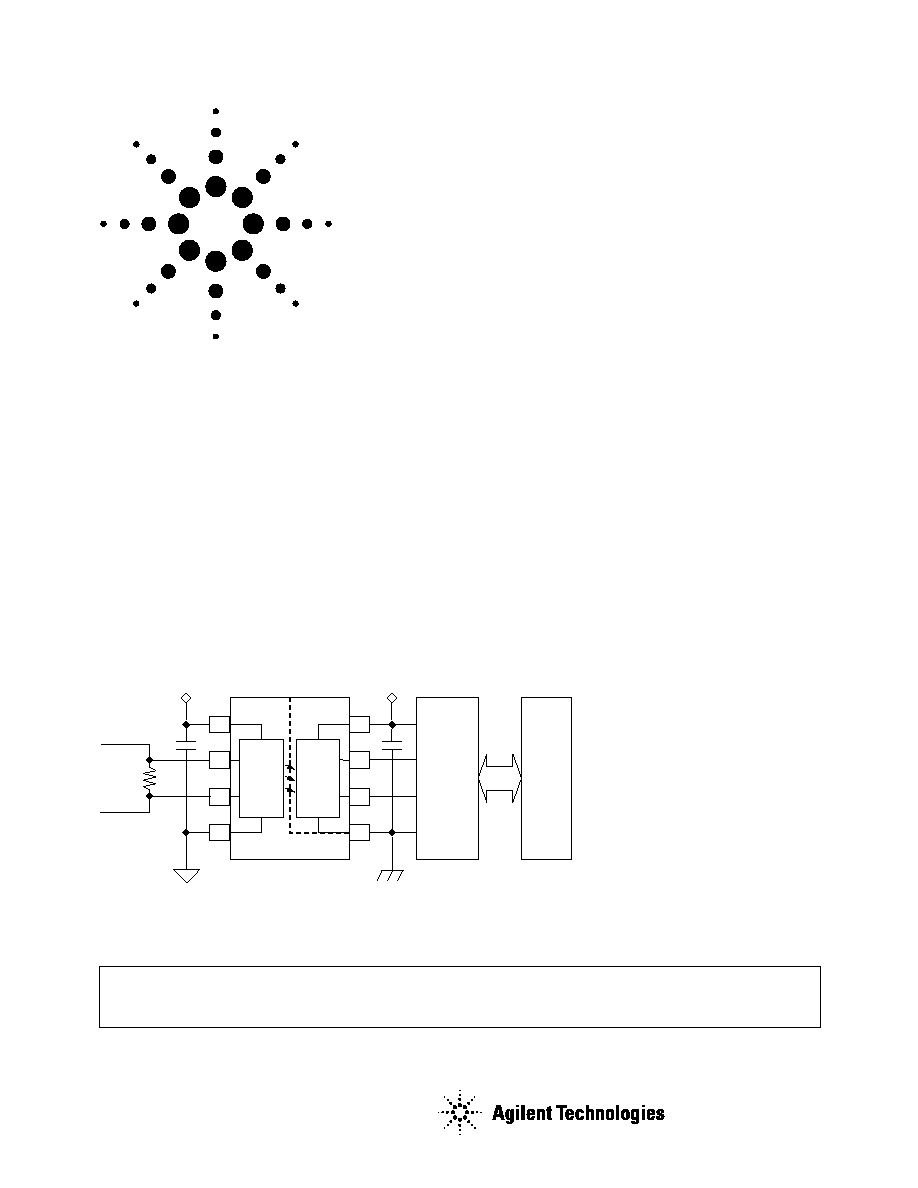
The HCPL-7860/HCPL-786J
Optically Isolated Modulator
and HCPL-0872 Digital
Interface IC or digital filter
together form an isolated
programmable two-chip
analog-to-digital converter. The
isolated modulator allows
direct measurement of motor
phase currents in power
inverters.
In operation, the HCPL-7860/
HCPL-786J Isolated Modulator
(optocoupler with 3750 V
RMS
dielectric withstand voltage
rating) converts a low-
bandwidth analog input into a
high-speed one-bit data stream
by means of a Sigma-Delta (
-
) over-sampling modulator.
This modulation provides for
high noise margins and
excellent immunity against
isolation-mode transients. The
modulator data and on-chip
sampling clock are encoded
and transmitted across the
isolation boundary where they
are recovered and decoded
into separate high-speed clock
and data channels.
A 0.1 µF bypass capacitor must be connected between pins V
DD
and Ground
CAUTION: It is advised that normal static precautions be taken in handling and assembly
of this component to prevent damage and/or degradation, which may be induced by ESD.
SPI and QSPI are trademarks of Motorola Corp.
Microwire is a trademark of National Semiconductor Inc.
SIGMA
DELTA
MOD./
ENCODE
DECODE
1
2
3
4
8
7
6
5
Input
Current
HCPL-0872
or
Digital Filter
MCU
or
DSP
HCPL-7860
2
Option data sheets available. Contact Agilent sales representative or authorized distributor.
Remarks: The notation "#" is used for existing products, while (new) products launched since 15th July 2001 and lead
free option will use ""
HCPL-7860#XXXX
No option = Standard DIP package, 50 units per tube.
300 = Gull Wing Surface Mount Option, 50 units per tube.
500 = Tape and Reel Packaging Option, 1000 units per reel.
XXXE = Lead-Free Option
HCPL-786J#XXXX
No option = Standard DIP package, 45 units per tube.
500 = Tape and Reel Packaging Option, 850 units per reel.
XXXE = Lead-Free Option
Ordering Information
Specify part number followed by option number (if desired).
Example:
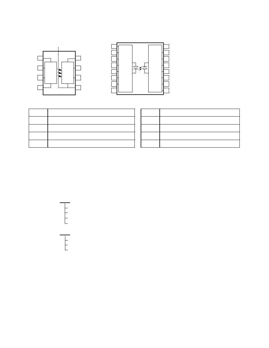
Pin Description
Symbol
Description
Symbol
Description
V
DD1
Supply voltage input (4.5 V to 5.5 V)
V
DD2
Supply voltage input (4.5 V to 5.5 V)
V
IN+
Positive input (± 200 mV recommended)
MCLK
Clock output (10 MHz typical)
V
IN-
Negative input (normally connected to GND1)
MDAT
Serial data output
GND1
Input ground
GND2
Output ground
HCPL-7860
1
2
3
4
8
7
6
5
V
DD1
V
IN+
V
IN-
GND1
V
DD2
MCLK
MDAT
GND2
SHIELD
ISOLATION
BOUNDARY
DECODE
SIGMA-
DELTA
MOD./
ENCODE
5
6
12
11
NC
NC
NC
MDAT
7
10
NC
NC
8
9
GND1
GND2
1
2
16
15
V
DD1
V
IN+
GND2
NC
3
14
V
IN-
V
DD2
4
13
NC
MCLK
SIGMA-
DELTA
MOD./
ENCODER
DECODER
HCPL-786J
3
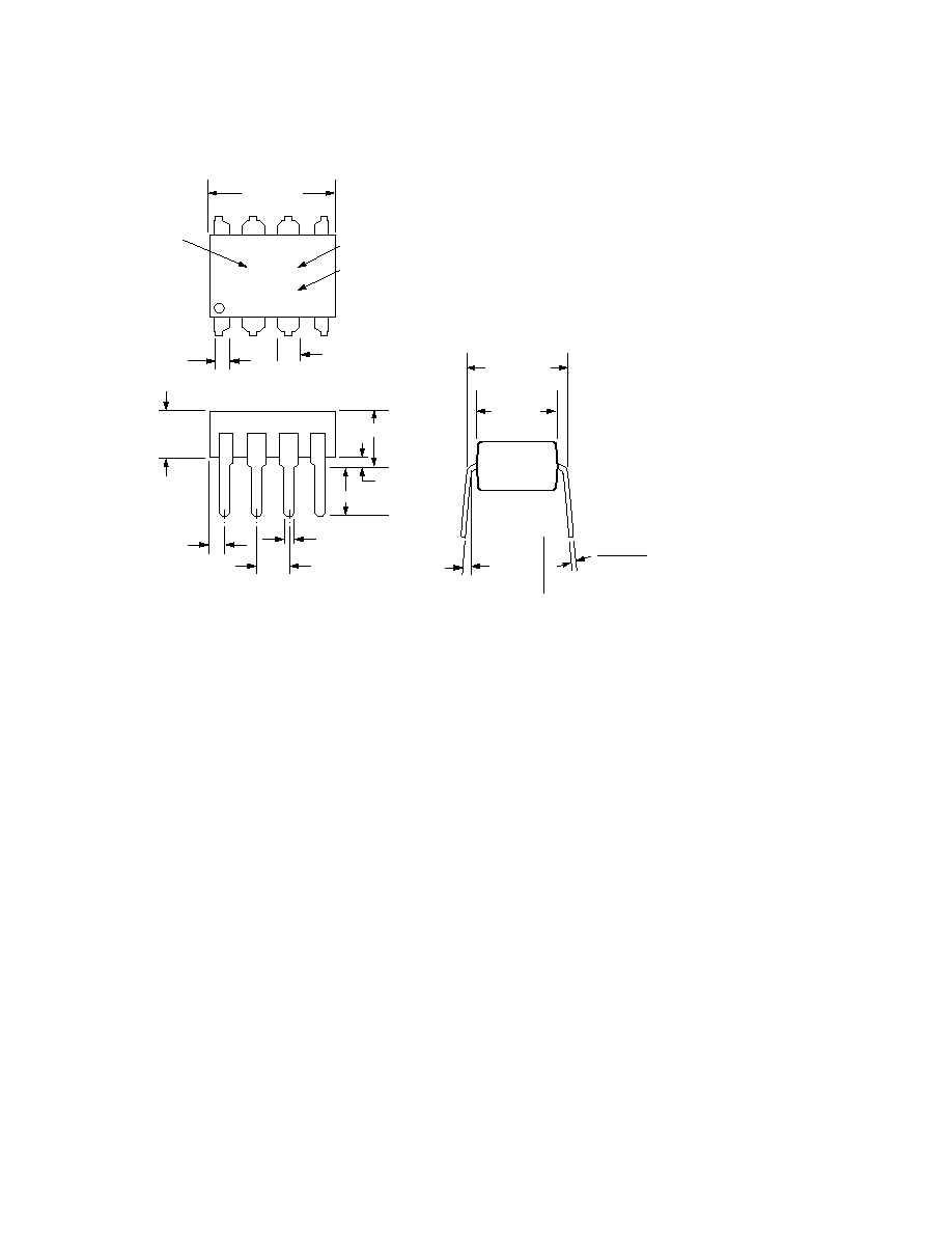
Package Outline Drawings
8-pin DIP Package
9.80 ± 0.25
(0.386 ± 0.010)
PIN ONE
1.78 (0.070) MAX.
1.19 (0.047) MAX.
A 7860X
YYWW
DATE CODE
0.51 (0.020) MIN.
0.65 (0.025) MAX.
4.70 (0.185) MAX.
2.92 (0.115) MIN.
5° TYP.
7.62 ± 0.25
(0.300 ± 0.010)
DIMENSIONS IN MILLIMETERS AND (INCHES).
NOTE: FLOATING LEAD PROTRUSION IS 0.5 mm (20mils) MAX.
NOTE: INITIAL OR CONTINUED VARIATION IN THE COLOUR OF THE HCPL-7860/HCPL-786J'S WHITE MOLD COMPOUND IS
NORMAL AND DOES NOT AFFECT DEVICE PERFORMANCE OR RELIABILITY.
*ALL UNITS WITHIN EACH HCPL-7860 STANDARD PACKAGING INCREMENT (EITHER 50 PER TUBE OR 1000 PER REEL) HAVE
A COMMON MARKING SUFFIX TO REPRESENT AN ABSOLUTE REFERENCE VOLTAGE TOLERANCE OF ± 1%. AN ABSOLUTE
REFERENCE VOLTAGE TOLERANCE OF ± 4% IS GUARANTEED BETWEEN STANDARD PACKAGING INCREMENTS.
5
6
7
8
4
3
2
1
REFERENCE VOLTAGE
MATCHING SUFFIX*
TYPE NUMBER
3.56 ± 0.13
(0.140 ± 0.005)
6.35 ± 0.25
(0.250 ± 0.010)
0.20 (0.008)
0.33 (0.013)
2.54 ± 0.25
(0.100 ± 0.010)
1.080 ± 0.320
(0.043 ± 0.013)
4
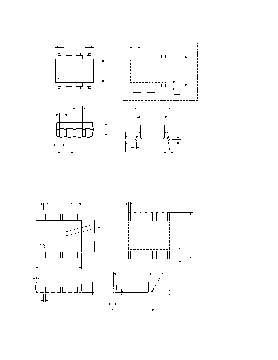
8-pin Gull Wing Surface Mount Option 300
16-Lead Surface Mount
0.635 ± 0.25
(0.025 ± 0.010)
12° NOM.
9.65 ± 0.25
(0.380 ± 0.010)
0.51 ± 0.130
(0.020 ± 0.005)
7.62 ± 0.25
(0.300 ± 0.010)
5
6
7
8
4
3
2
1
9.80 ± 0.25
(0.386 ± 0.010)
6.350 ± 0.25
(0.250 ± 0.010)
1.016 (0.040)
1.27 (0.050)
10.9 (0.430)
2.0 (0.080)
LAND PATTERN RECOMMENDATION
1.080 ± 0.320
(0.043 ± 0.013)
3.56 ± 0.13
(0.140 ± 0.005)
1.780
(0.070)
MAX.
1.19
(0.047)
MAX.
2.540
(0.100)
BSC
0.20 (0.008)
0.33 (0.013)
NOTE: FLOATING LEAD PROTRUSION IS 0.15 mm (6 mils) MAX.
DIMENSIONS IN MILLIMETERS (INCHES).
TOLERANCES (UNLESS OTHERWISE SPECIFIED): xx.xx = 0.01
xx.xxx = 0.005
LEAD COPLANARITY
MAXIMUM: 0.102 (0.004)
9
7.493 ± 0.254
(0.295 ± 0.010)
10
11
12
13
14
15
16
8
7
6
5
4
3
2
1
0.457
(0.018)
3.505 ± 0.127
(0.138 ± 0.005)
9°
10.312 ± 0.254
(0.406 ± 0.10)
10.160 ± 0.254
(0.408 ± 0.010)
0.025 MIN.
0.203 ± 0.076
(0.008 ± 0.003)
STANDOFF
8.986 ± 0.254
(0.345 ± 0.010)
0-8°
0.457
(0.018)
1.270
(0.050)
ALL LEADS
TO BE
COPLANAR
± 0.002
A 786J
YYWW
TYPE NUMBER
DATE CODE
DIMENSIONS IN MILLIMETERS AND (INCHES).
NOTE: Initial and continued variation in the color of the HCPL-786J's white mold compound is normal
and does not affect device performance or reliability.
NOTE: FLOATING LEAD PROTRUSION IS 0.15 mm (6 mils) MAX.
11.63 (0.458)
2.16 (0.085)
0.64 (0.025)
LAND PATTERN RECOMMENDATION
5
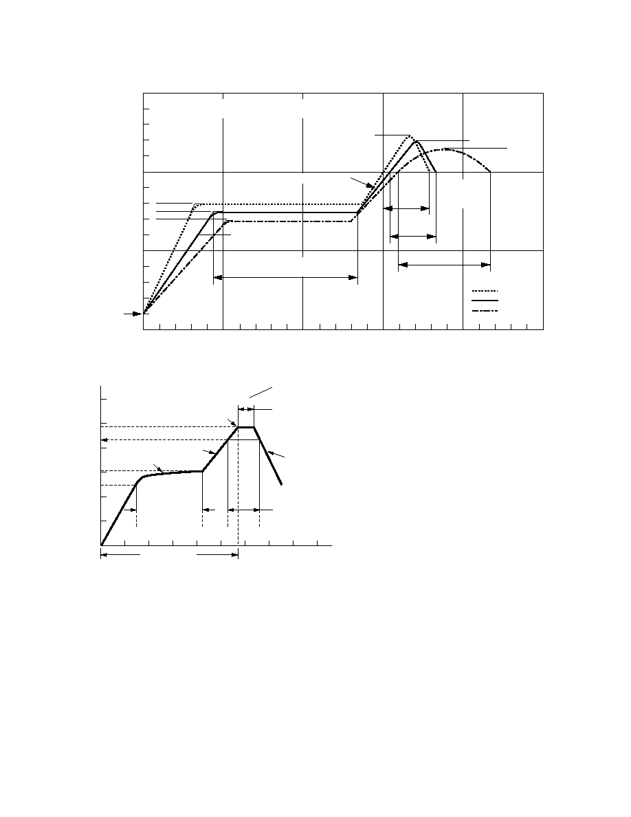
Solder Reflow Temperature Profile
Recommended Lead Free IR Profile
217°C
RAMP-DOWN
6°C/SEC. MAX.
RAMP-UP
3°C/SEC. MAX.
150 - 200°C
260 +0/-5°C
t 25°C to PEAK
60 to 150 SEC.
20-40 SEC.
TIME WITHIN 5°C of ACTUAL
PEAK TEMPERATURE
tp
t
s
PREHEAT
60 to 180 SEC.
t
L
T
L
T
smax
T
smin
25
T
p
TIME (SECONDS)
TEMPERATURE (
°
C)
NOTES:
THE TIME FROM 25°C to PEAK TEMPERATURE = 8 MINUTES MAX.
T
smax
= 200°C, T
smin
= 150°C
UL
Approval under UL 1577,
component recognition program
up to V
ISO
= 3750 V
RMS
.
File E55361.
IEC/EN/DIN EN 60747-5-2
Approved under:
IEC 60747-5-2:1997 + A1:2002
EN 60747-5-2:2001 + A1:2002
DIN EN 60747-5-2 (VDE 0884 Teil 2):2003-01.
Regulatory Information
The HCPL-7860/HCPL-786J has been approved by the following organizations:
CSA
Approval under CSA Component
Acceptance Notice #5, File CA
88324.
0
TIME (SECONDS)
TEMPERATURE (°C)
200
100
50
150
100
200
250
300
0
30
SEC.
50 SEC.
30
SEC.
160°C
140°C
150°C
PEAK
TEMP.
245°C
PEAK
TEMP.
240°C
PEAK
TEMP.
230°C
SOLDERING
TIME
200°C
PREHEATING TIME
150°C, 90 + 30 SEC.
2.5°C ± 0.5°C/SEC.
3°C + 1°C/-0.5°C
TIGHT
TYPICAL
LOOSE
ROOM
TEMPERATURE
PREHEATING RATE 3°C + 1°C/-0.5°C/SEC.
REFLOW HEATING RATE 2.5°C ± 0.5°C/SEC.