 | –≠–ª–µ–∫—Ç—Ä–æ–Ω–Ω—ã–π –∫–æ–º–ø–æ–Ω–µ–Ω—Ç: HDMP-1032 | –°–∫–∞—á–∞—Ç—å:  PDF PDF  ZIP ZIP |

Agilent HDMP-1032/1034
Transmitter/Receiver
Chip Set
Data Sheet
Features
∑ 3.3 V supply, low power
dissipation
590 mW Tx, 660 mW Rx
∑ On-chip encode/decode using
Conditional Inversion Master
Transition (CIMT) protocol
∑ 1:N broadcast ready
configurable receiver inputs allow
multi-point data broadcast using a
single transmitter
∑ Parallel Automatic
Synchronization System (PASS)
allows receiver to read recovered
words with local reference clock
∑ Robust simplex mode
∑ Wide range serial rate
260-1400 MBaud (user selectable)
∑ 5 V tolerant TTL interface
16 or 17 Bits wide
∑ Low cost 64 pin plastic package
14x14 mm
2
PQFP
Applications
∑ Cellular base station
∑ ATM switch
∑ Backplane/bus extender
∑ Video, image acquisition
∑ Point to point data link
∑ Implement SCI-FI standard
Description
The HDMP-1032 transmitter and
HDMP-1034 receiver are used
together to build a high-speed
data link for point-to-point
communication. These silicon
bipolar transmitter and receiver
chips are housed in standard
plastic 64 pin PQFP packages.
From the user's viewpoint, these
products can be thought of as a
"virtual ribbon cable" interface for
the transmission of data and con-
trol words. A parallel word loaded
into the Tx (transmitter) chip is
delivered to the Rx (receiver)
chip over a serial channel and is
then reconstructed into its origi-
nal parallel form. The channel
can be either a coaxial copper
cable or optical link
The chip set hides from the
user the complexity of encoding,
multiplexing, clock extraction,
demultiplexing and decoding. The
CIMT encoding scheme used en-
sures the DC balance of the serial
line. When data or control words
are not being sent the transmitter
sends idle words.
The serial data rate of the Tx/Rx
link is selectable in three ranges
and extends from 208 to 1120
Mbit/s. This translates into an
encoded serial rate of 260 to
1400 MBaud. The parallel data
interface is 16 bit TTL. A flag bit
is also present and can be used as
an extra 17th bit under the user's
control. This bit can be used as
an even or odd word indicator
for dual-word transmission. The
encoding of the flag bit can be
scrambled to reduce the probabil-
ity of erroneous word alignment.
A user control space is also
provided. If TXCNTL is asserted
on the Tx chip, the least signifi-
cant 14 bits of the data will be
sent and the RXCNTL line on the
Rx chip will indicate the data is
a Control Word.
At the Rx, the PASS feature
allows the recovered words to
be clocked out with the local
1.4 GBd Transmitter/Receiver Chip Set with
CIMT Encoder/Decoder and Variable Data Rate.

2
REFCLK. This feature is particu-
larly useful when the Tx clock
and REFCLK are synchronous.
The PASS system also supports
synchronization of multiple
channels.
The chipset is compatible with
previous versions of the G-Link
chipset (HDMP-10x2/10x4) pro-
vided the latter are used in 16 bit
Simplex with Periodic Sync Pulse
or External Reference Oscillator
Mode (Simplex Method II or III).
Table of Contents
Topic
Page
Typical Applications ................................................................................................... 3
Setting the Operating Data Rate Range .................................................................. 4
Transmitter Block Diagram ....................................................................................... 5
Receiver Block Diagram ............................................................................................ 6
Parallel Automatic Synchronization System .......................................................... 7
Transmitter Timing .................................................................................................... 10
Receiver Timing ........................................................................................................... 11
DC Electrical Specifications ..................................................................................... 12
AC Electrical Specifications ..................................................................................... 12
TXCLK and REFCLK Requirements ........................................................................... 13
Absolute Maximum Ratings ...................................................................................... 13
Thermal Characteristics ............................................................................................ 14
I/O Type Definitions .................................................................................................... 14
Pin-Out Diagrams ........................................................................................................ 15
Transmitter Pin Definitions ........................................................................................ 16
Receiver Pin Definitions ............................................................................................ 18
Mechanical Dimensions ............................................................................................ 21
Appendix: Internal Architecture Information
Line Code Description ................................................................................................ 22
Data, Control, and Idle Word Codes ........................................................................ 22
Tx Operation Principles ≠ Encoding & Phase Lock Loop .................................... 24
Rx Operation Principles ≠ Decoding & Phase Lock Loop .................................... 25
Integrator Capacitor & Power Supply
Bypassing/Grounding ................................................................................................. 26
TTL and High Speed I/O ............................................................................................. 26
Data Bus Line/Broadcast Transmission ................................................................. 27
Nomenclature Changes between
HDMP-1032/34 and HDMP-1022/24 .......................................................................... 30
Pin Cross Reference Table ........................................................................................ 31

3
Typical Applications
The HDMP-1032/1034 chipset
was designed for ease of use
and flexibility. The customer can
tailor the use of this product
through the configuration of the
link based on specific system re-
quirements and application needs.
Typical applications range from
backplane serialization and bus
extension to cellular base stations.
All modes are built up from the
basic simplex transmission mode
as shown in Figure 1a.
For digital video transmission,
simplex links are common. The
HDMP-1032/1034 chipset can
transmit 16 bits of parallel data
in standard or broadcast simplex
mode (Figures 1a, 1b).
If the bus is 32 bits wide, the
HDMP-1032/1034 chipset is ca-
pable of sending this data word as
two separate word segments with
the use of an external mux and
demux as shown in Figure 1c. In
this mode, the transmitter and
receiver use the FLAG bit to indi-
cate the first or second word
segment. The HDMP-1032/1034
chipset may also be configured
in full duplex to achieve a 32 bit
wide bus extension. In addition,
32 bit wide data can be transmit-
ted over two parallel serial lines
as shown in Figure 1d.
Low latency bus extension of
a 16 bit wide data bus may be
achieved using the full duplex
configuration (Figure 1e). In this
mode, link startup is achieved
by exchange of control words.
Figure 1. Various configurations using the HDMP-1032/1034.
Tx
Rx
TXCLK
RXCLK0/1
A) 16 BIT SIMPLEX TRANSMISSION
REFCLK
TXCLK
Tx
Rx
RXCLK0/1
B) 16 BIT BROADCAST TRANSMISSION
Rx
RXCLK0/1
Rx
RXCLK0/1
REFCLK
REFCLK
REFCLK
TXCLK
Tx
Rx
RXCLK0/1
MUX
DEMUX
C) 32 BIT SIMPLEX TRANSMISSION
REFCLK
TXCLK
Tx
Rx
RXCLK0/1
TXCLK
Tx
Rx
RXCLK0/1
D) 32 BIT SIMPLEX TRANSMISSION
REFCLK
REFCLK
TXCLK
Tx
Rx
RXCLK0/1
RXCLK0/1
Rx
Tx
TXCLK
E) 16 BIT DUPLEX TRANSMISSION
REFCLK
REFCLK
4
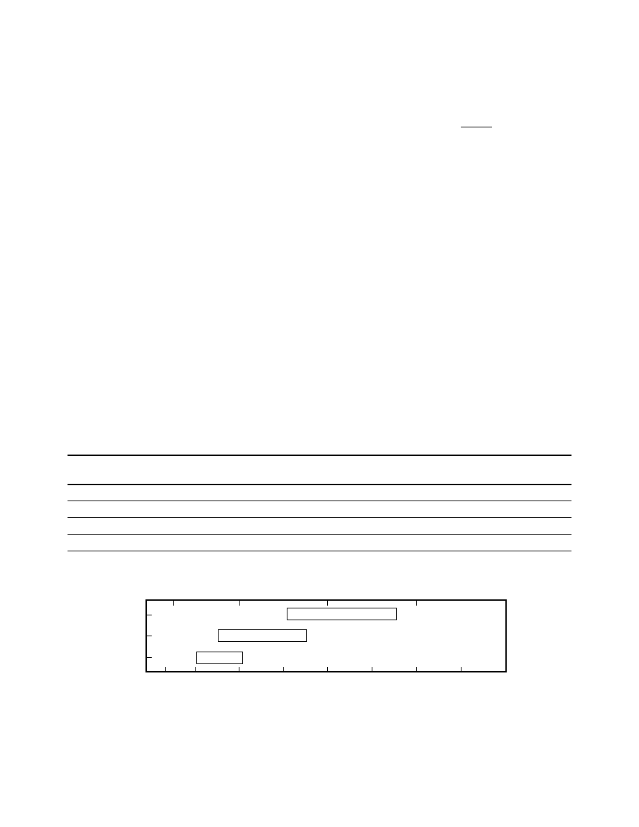
HDMP-1032 (Tx), HDMP-1034 (Rx)
Typical Operating Rates
1,2
Tc = ≠20
∞
C to +85
∞
C, V
CC
= 3.15V to 3.45V
Parallel Word Rate
Serial Data Rate
Serial Baud Rate
(MWord/sec)
(MBits/sec)
(MBaud)
DIV1
DIV0
Range
Range
Range
0
0
40 70 (max)
640 1120 (max)
800 1400 (max)
0
1
20 45
320 720
400 900
1
0
13 (min) 26
208 (min) 416
260 (min) 520
Figure 2. Typical data rates showing ranges of operation
1
.
Notes:
1. All values in this table and graph are typical unless otherwise noted by (min) or (max), (min) indicates a minimum guaranteed value,
(max) indicates a maximum guaranteed value.
2. All values in this table are expected for a BER less than 10
-14
.
0/0
0/1
1/0
5
25
50
75
100
2000
1500
1000
500
100
800
400
260 (MIN.)
520
900
1400 (MAX.)
DIV 1 / DIV 0
SERIAL BAUD RATE (MBaud)
WORD RATE (MWords/sec)
is unique. The user serial data
rate is calculated as:
The baud rate includes an addi-
tional four encoding bits (20 bits
total) that the HDMP-1032/34
G-Link chipset transmits. The
serial baud rate is calculated as:
Example 2 (Overlapping Ranges)
Some applications may have a
parallel word rate that seems
to fit in two ranges of opera-
tion. For example, a 42.5 MHz
(42.5 MWord/s) parallel data
rate falls within two ranges:
DIV1/0 = (0/0) and DIV1/0 =
(0/1). According to the table, a
setting of DIV1/0 = (0/1) gives
Serial Baud Rate =
(≠≠≠≠≠) (≠≠≠≠≠) =
1200 MBaud
20bits
Word
60MW
sec
Serial Data Rate =
(≠≠≠≠≠) (≠≠≠≠≠) =
960 MBits/sec
16bits
Word
60MW
sec
Setting the Operating Data Rate Range
The HDMP-1032/1034 chipset
can operate from 260 MBaud to
1400 MBaud. It is divided into
three operating data ranges with
each range selected by setting
DIV1/0 as shown in the Typical
Operating Rates table. Two
examples have been provided in
order to help in understanding
and using this table.
Example 1 (Unique Range)
It is desired to transmit a 16 bit
parallel word operating at a fre-
quency of 60 MHz (60 MWord/
sec). Both the Tx and Rx must
be set to a range that covers this
word rate. According to the table
only a setting of DIV1/0 = (0/0)
allows a parallel input word rate
of 40 to 70 MHz. This range
setting easily accommodates the
required 60 MHz word rate and
an upper rate of 45 MHz while a
setting of DIV1/0 = (0/0) gives a
lower rate of 40 MHz. The upper
and lower data rates stated in the
tables are typical values unless
indicated by (min) or (max) and
may vary between individual parts.
However, each transmitter/receiver
has overlapping ranges of opera-
tion providing continuous band
coverage from 260 to 1400 MBaud.
In this example, each transmitter/
receiver will permit a 42.5 MHz
parallel data rate but it is sug-
gested that DIV0 be tied to a
jumper that can be set either to
logic `1' (open allowing DIV0 to
float high) or logic `0' (ground).
This allows the design to accom-
modate both ranges for maximum
flexibility. This technique is rec-
ommended whenever operating
near the upper and lower ends of
two adjacent word rate ranges.

5
Figure 3. HDMP-1032 Transmitter Block Diagram.
The C-Field logic, based on the
inputs at TXCNTL, TXDATA,
TXFLGENB and TXFLAG, sup-
plies the four bits of the C-field
to the encoded word mux. These
bits contain information regard-
ing the word type: Control, Data
or Idle. In order for the TXFLAG
bit to be used as an additional
data bit, TXFLGENB must be set
high on the Tx and RXFLGENB
must be set high on the Rx. If
scrambling of the encoding of the
flag bit is desired, ESMPXENB pin
must be set high on both the Tx
and Rx. See Flag Descrambler
section on next page for a more
detailed description of the
enhanced simplex mode.
The W-Field logic (word field)
presents either bits TX[0-15]
or an Idle Word to the encoded
word mux.
Encoded Word Mux
The Word Mux accepts the four
encoding bits from the C-Field
and 16 data bits from the
W-Field. These 20 bits of parallel
information are then multiplexed
to a serial line based on the
internal high-speed serial clock.
HDMP-1032 Tx Block Diagram
The HDMP-1032 transmitter was
designed to accept 16 bit wide
parallel words and transmit them
over a high-speed serial line. The
HDMP-1032 performs the follow-
ing functions:
∑ Latching parallel word input
∑ Phase lock to TXCLK
∑ High speed clock multiplication
∑ Word encoding
∑ Parallel to Serial Multiplexing
PLL/Clock Generator
The Phase Lock Loop and Clock
Generator are responsible for
generating all the internal clocks
needed by the transmitter to
perform its functions. These
clocks are based on a supplied
word clock (TXCLK) and control
signals (TXDIV1/0, TCLKENB).
TXCLK is the incoming word
clock. The PLL/Clock Generator
locks on to this incoming
rate and multiplies the word
rate clock by 20 (16 word bits
+ 4 encoding bits). As lock is
achieved, LOCKED is set high.
The TXDIV1/0 pins configure the
transmitter to accept incoming
data words within the desired
frequency range.
By setting TCLKENB high, the
user may provide an external
TTL high speed serial clock at
TXCLK. This clock replaces the
internal VCO clock and is in-
tended for diagnostic purposes
only. This uncharacterized signal
is used directly by the high-speed
serial circuitry to output the se-
rial data at speeds that are not
within the VCO range.
C-Field and W-Field
Encoder Logic
This logic determines what infor-
mation is sent to the encoded
word mux. If TXCNTL is high, the
logic sends bits TX[0-13] and a
C-Field (coding field) encoded
as a control word regardless of
the state of TXDATA. If TXCNTL
is low and TXDATA is high,
the logic sends TX[0-15] and a
C-Field encoded as a data word.
If neither TXCNTL nor TXDATA
is set high, then the transmitter
assumes the link is not being
used. In this case, the logic sub-
mits an Idle Word to the encoded
word mux to maintain the DC
balance on the serial link and
allow the receiver to maintain
frequency and phase lock.
C-FIELD
ENCODER
TXFLAG
TX[0-15]
W-FIELD
ENCODER
INVERT
WORD
MUX
TXFLGENB
ESMPXENB
TXCLK
TXDIV1/0
TCLKENB
LOCKED
PLL / CLOCK
GENERATOR
ACCUMULATE
TXCAP0
TXCAP1
HSOUT
FLAG
ENCODER
TXDATA
TXCNTL
LATCH
INPUT
INPUT
LATCH
SIGN
+