 | –≠–ª–µ–∫—Ç—Ä–æ–Ω–Ω—ã–π –∫–æ–º–ø–æ–Ω–µ–Ω—Ç: HDSP-3900 | –°–∫–∞—á–∞—Ç—å:  PDF PDF  ZIP ZIP |
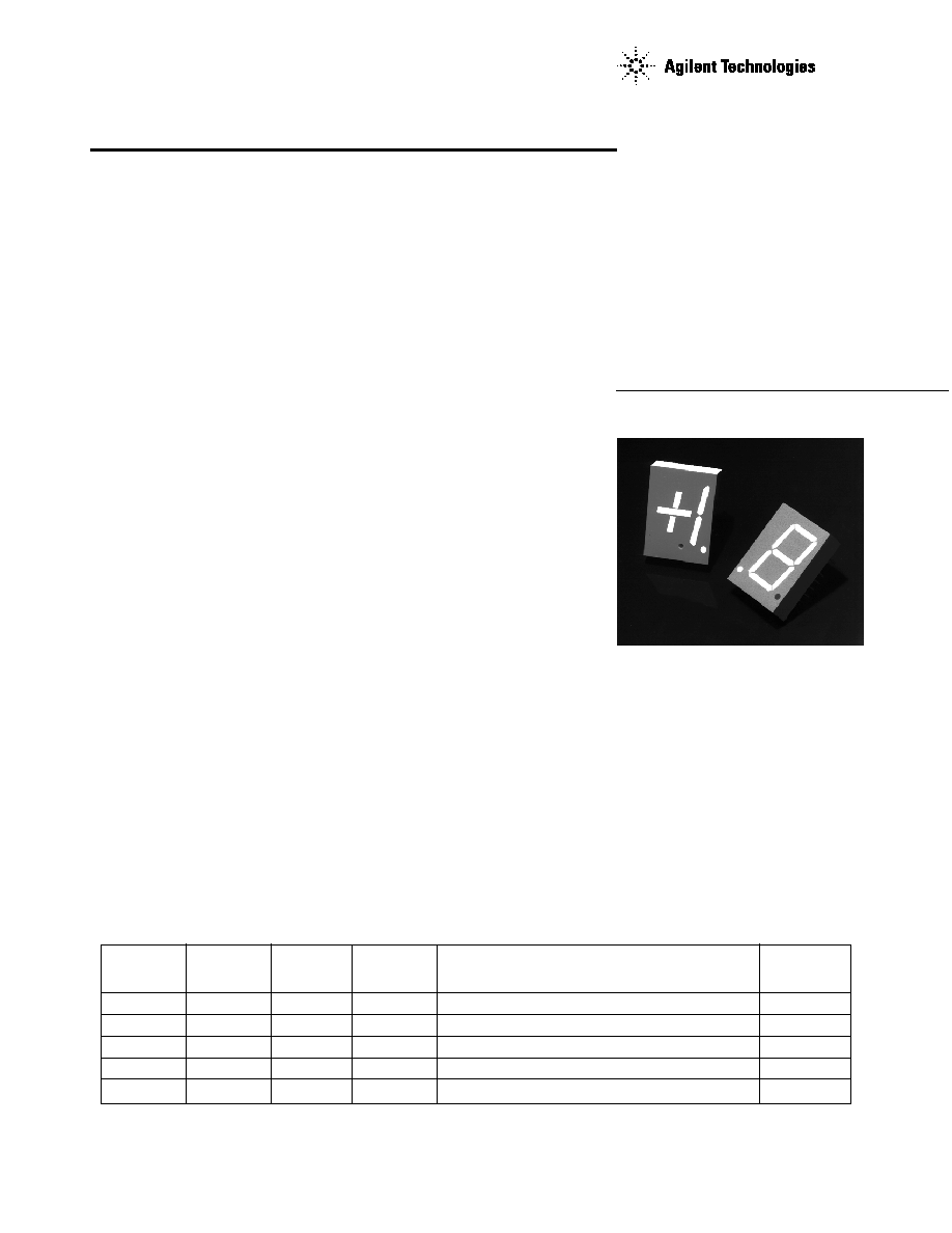
20 mm (0.8 inch)
Seven Segment Displays
Technical Data
AlGaAs
[1]
HER
Yellow
Green
Package
HDSP-
HDSP-
HDSP-
HDSP-
Description
Drawing
N150
3900
4200
8600
Common Anode Left Hand Decimal
A
N151
3901
4201
8601
Common Anode Right Hand Decimal
B
N153
3903
4203
8603
Common Cathode Right Hand Decimal
C
N155
3905
4205
8605
Common Cathode Left Hand Decimal
D
N156
3906
4206
8606
Universal
±
1. Overflow
[2]
E
Notes:
1. These displays are recommended for high ambient light operation. Please refer to the HDSP-N10X AlGaAs data sheet for low
current operation.
2. Universal pinout brings the anode and cathode of each segment's LED out to separate pins. See internal diagram E.
Devices
Features
∑ Industry Standard Size
∑ Industry Standard Pinout
15.24 mm (0.6 in.) DIP Leads
on 2.54 mm (0.1 in.) Centers
∑ Choice of Colors
AlGaAs Red, High Efficiency
Red, Yellow, Green
∑ Excellent Appearance
Evenly Lighted Segments
Mitered Corners on Segments
Gray Package Gives Optimum
Contrast
±
50
∞
Viewing Angle
∑ Design Flexibility
Common Anode or Common
Cathode
Left and Right Hand Decimal
Points
±
1. Overflow Character
∑ Categorized for Luminous
Intensity
Yellow and Green Categorized
for Color
Use of Like Categories Yields a
Uniform Display
∑ High Light Output
∑ High Peak Current
∑ Excellent for Long Digit
String Multiplexing
Intensity and Color
Selection Option
See Intensity and Color
Selected Displays Data Sheet
∑ Sunlight Viewable AlGaAs
Description
The 20 mm (0.8 inch) LED seven
segment displays are designed
for viewing distances up to 10
metres (33 feet). These devices
use an industry standard size
package and pinout. All devices
are available as either common
anode or common cathode.
These displays are ideal for most
applications. Pin for pin
equivalent displays are also
available in a low current design.
The low current displays are ideal
for portable applications. For
additional information see the
Low Current Seven Segment
Displays data sheet.
HDSP-390X Series
HDSP-420X Series
HDSP-860X Series
HDSP-N15X Series
2
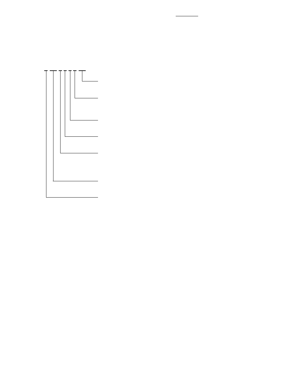
Part Numbering System
Notes:
1. For codes not listed in the figure above, please refer to the respective datasheet or contact your nearest
Agilent representative for details.
2. Bin options refer to shippable bins for a part number. Color and Intensity Bins are typically restricted to 1
bin per tube (exceptions may apply). Please refer to respective datasheet for specific bin limit information.
5082 -X X X X-X X X X X
HDSP-X X X X-X X X X X
Mechanical Options
[1]
00: No Mechanical Option
Color Bin Options
[1,2]
0: No Color Bin Limitation
Z: Color Bins 2- and 3+ Only (applicable for Yellow devices only)
Maximum Intensity Bin
[1,2]
0: No Maximum Intensity Bin Limitation
Minimum Intensity Bin
[1,2]
0: No Minimum Intensity Bin Limitation
Device Configuration/Color
[1]
0: Common Anode
1: Common Anode
3: Common Cathode
Device Specific Configuration
[1]
Refer to Respective Datasheet
Package
[1]
N: 20 mm (0.8 inch) Single Digit Seven Segment Display

3
HDSP-39xx
Package Dimensions
Internal Circuit Diagram
E
D
C
B
A
4
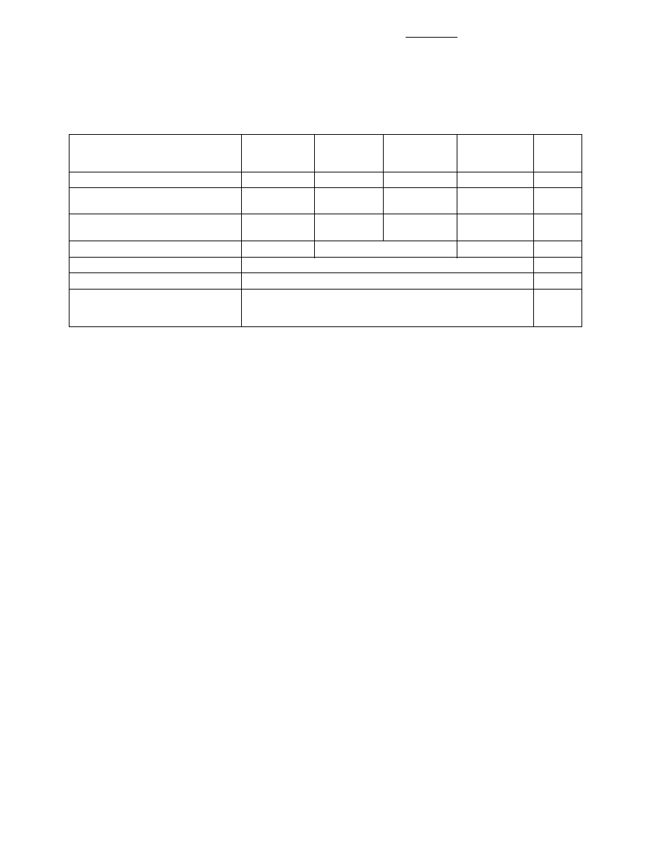
Absolute Maximum Ratings
AlGaAs Red
HER
Yellow
Green
HDSP-N150
HDSP-3900
HDSP-4200
HDSP-8600
Description
Series
Series
Series
Series
Units
Average Power per Segment or DP
96
105
105
105
mW
Peak Forward Current per
160
[1]
135
[3]
135
[3]
90
[5]
mA
Segment or DP
DC Forward Current per
40
[2]
40
[4]
40
[4]
30
[6]
mA
Segment or DP
Operating Temperature Range
≠20 to +100
[7]
≠40 to +100
≠40 to +100
∞
C
Storage Temperature Range
≠55 to +100
∞
C
Reverse Voltage per Segment or DP
3.0
V
Lead Solder Temperature for 3
Seconds (1.60 mm [0.063 in.]
260
∞
C
below seating plane)
Notes:
1. See Figure 2 to establish pulsed conditions.
2. Derate above 55
∞
C at 0.8 mA/
∞
C.
3. See Figure 7 to establish pulsed conditions.
4. Derate above 50
∞
C at 0.73 mA/
∞
C.
5. See Figure 8 to establish pulsed conditions.
6. Derate above 50
∞
C at 0.54 mA/
∞
C.
7. For operation below ≠20
∞
C, contact your local Agilent components sales office or an authorized distributor.
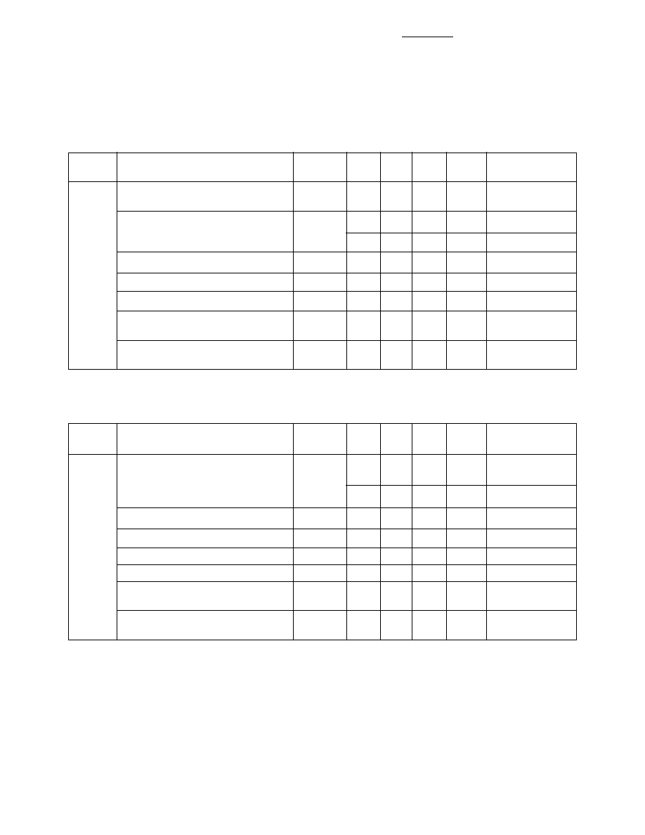
5
Device
Series
Parameter
Symbol
Min.
Typ.
Max.
Units
Test Conditions
Luminous Intensity/Segment
[1,2,5]
I
V
6.0
14.0
mcd
I
F
= 20 mA
(Digit Average)
1.8
V
I
F
= 20 mA
Forward Voltage/Segment or DP
V
F
2.0
3.0
V
I
F
= 100 mA
HDSP-
N15X
Peak Wavelength
PEAK
645
nm
Dominant Wavelength
[3]
d
637
nm
Reverse Voltage/Segment or DP
[4]
V
R
3.0
15
V
I
R
= 100
µ
A
Temperature Coefficient of
V
F
/
∞
C
-2
mV/
∞
C
V
F
/Segment or DP
Thermal Resistance LED Junction-
R
J-PIN
430
∞
C/W/
to-Pin
Seg
High Efficiency Red
Device
Series
Parameter
Symbol
Min.
Typ.
Max.
Units
Test Conditions
3350
7000
µ
cd
I
F
= 100 mA Peak:
Luminous Intensity/Segment
[1,2]
I
V
1 of 5 df
(Digit Average)
4800
µ
cd
I
F
= 20 mA
Forward Voltage/Segment or DP
V
F
2.6
3.5
V
I
F
= 100 mA
HDSP-
390X
Peak Wavelength
PEAK
635
nm
Dominant Wavelength
[3]
d
626
nm
Reverse Voltage/Segment or DP
[4]
V
R
3.0
25
V
I
R
= 100
µ
A
Temperature Coefficient of
V
F
/
∞
C
-2
mV/
∞
C
V
F
/Segment or DP
Thermal Resistance LED Junction-
R
J-PIN
375
∞
C/W/
to-Pin
Seg
AlGaAs Red
Electrical/Optical Characteristics at T
A
= 25
∞
C