Devices
High
High
AlGaAs
Efficiency
Performance
Red
Red
Green
Description
HDSP-M101
HDSP-4501
HDSP-5101
26.5 mm Common Row Anode
HDSP-M103
HDSP-4503
HDSP-5103
26.5 mm Common Row Cathode
Features
∑ Multiple Colors Available
∑ Large Character Height
∑ 5 X 7 Dot Matrix Font
∑ Viewable Up to 18 Meters
(26.5 mm Display)
∑ X-Y Stackable
∑ Ideal for Graphics Panels
∑ Available in Common Row
Anode and Common Row
Cathode Configurations
∑ AlGaAs Displays Suitable for
Low Power or Bright
Ambients
Typical Intensity 1650 mcd
at 2 mA Average Drive
Current
∑ Categorized for Intensity
∑ Mechanically Rugged
∑ Green Categorized for Color
Description
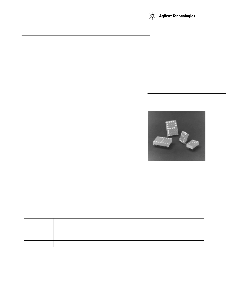
The large 5 X 7 dot matrix alpha-
numeric display family consists of
26.5 mm (1.04 inch) and 17.3
mm (0.68 inch) character height
packages. These devices have
excellent viewability; the 26.5
mm character can be read at up
to 18 meters (12 meters for the
0.68 inch part).
The 26.5 mm font has a 10.2 mm
(0.4 inch) dual-in-line (DIP) con-
figuration, while the 17.3 mm font
has an industry standard 7.6 mm
(0.3 inch) DIP configuration.
HDSP-450x Series
HDSP-510x Series
HDSP-M10x Series
Applications include electronic
instrumentation, computer
peripherals, point of sale termi-
nals, weighing scales, and indus-
trial electronics.
Large 5 X 7 Dot Matrix
Alphanumeric Displays
17.3/26.5 mm Character Heights
Technical Data

2
Part Numbering System
HDSP - X X X X
Device Configuration/Color
[1]
1: Common Row Anode
3: Common Row Cathode
Character Height/Device Configuration
[1]
Refer to Respective Datasheet
Package Configuration
[1]
1: 1.04 inch Character Height (for HDSP-5xxx only)
4: 0.68 inch Character Height (for HDSP-5xxx only)
5: 5 x 7 Dot Matrix
Package Type/Color
[1]
5: 5 x 7 Dot Matrix
L: 17.3 mm (0.68 inch) 5 x 7 Dot Matrix
M: 26.5 mm (1.04 inch) 5 x 7 Dot Matrix
Notes:
1. For codes not listed in the figure above, please refer to the respective datasheet or contact your nearest
Agilent representative for details.
2. Bin options refer to shippable bins for a part number. Color and Intensity Bins are typically restricted to 1
bin per tube (exceptions may apply). Please refer to respective datasheet for specific bin limit information.
3
FUNCTION
HDSP-M101/ HDSP-M103/
PIN
-4501/-5101 -4503/-5103
1
COLUMN 1 CATHODE ROW 1 CATHODE
2
NO PIN NO PIN
3
ROW 3 ANODE COLUMN 3 ANODE
4
COLUMN 2 CATHODE ROW 3 CATHODE
5
NO PIN NO PIN
6
ROW 5 ANODE COLUMN 1 ANODE
7
NO PIN NO PIN
8
ROW 6 ANODE COLUMN 2 ANODE
9
ROW 7 ANODE ROW 7 CATHODE
10
COLUMN 3 CATHODE ROW 6 CATHODE
11
COLUMN 5 CATHODE COLUMN 4 ANODE
12
NO PIN NO PIN
13
ROW 4 ANODE ROW 5 CATHODE
14
NO PIN NO PIN
15
COLUMN 4 CATHODE ROW 4 CATHODE
16
ROW 2 ANODE ROW 2 CATHODE
17
NO PIN NO PIN
18
ROW 1 ANODE COLUMN 5 ANODE
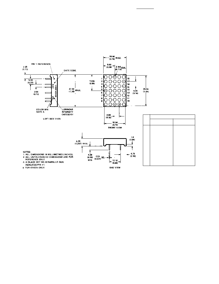
HDSP-M10x/450x/510x Series
Package Dimensions

4
Internal Circuit Diagrams
HDSP-M101/4501/5101
HDSP-M103/4503/5103
COMMON ANODE ROW
COMMON CATHODE ROW
Notes:
1. Average power is based on 20 dots per character. Total package power dissipation should not exceed 1.5 W.
2. Do not exceed maximum average current per dot.
3. For the HDSP-L10X/M10X series displays, derate maximum average current above 35
∞
C at 0.31 mA/
∞
C. For the HDSP-L20X/450X
series and HDSP-540X/510X series displays, derate maximum average current above 35
∞
C at 0.2 mA/
∞
C. This derating is based on a
device mounted in a socket having a thermal resistance junction to ambient of 50
∞
C/W per package.
Absolute Maximum Ratings at 25
∞
C
Description
HDSP-M10X Series
HDSP-450X Series
HDSP-510X Series
Average Power per Dot
75 mW
(T
A
= 25
∞
C)
[1]
Peak Forward Current per Dot
125 mA
90 mA
90 mA
(T
A
= 25
∞
C)
[1,2]
Average Forward Current per Dot
23 mA
15 mA
15 mA
(T
A
= 25
∞
C)
[1,3]
Operating Temperature Range
≠20
∞
C to +85
∞
C
≠40
∞
C to +85
∞
C
≠20
∞
C to +85
∞
C
Storage Temperature Range
≠40
∞
C to +85
∞
C
Wave Soldering Temperature
250
∞
C for 3 s
(1.59 mm [0.062 in.] below Body)
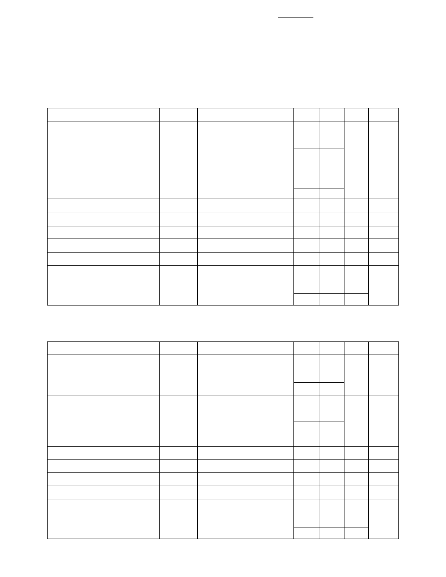
5
Electrical/Optical Characteristics at T
A
= 25
∞
C
AlGaAs Red HDSP-M10x Series
Description
Symbol
Test Conditions
Min.
Typ.
Max.
Units
Luminous Intensity/Dot
[4]
10 mA pk: 1 of 5
(Digit Average)
I
V
Duty Factor (2 mA Avg.)
HDSP-L10x (17.3 mm)
730
1650
HDSP-M10x (26.5 mm)
760
1850
Luminous Intensity/Dot
[4]
30 mA pk: 1 of 14
(Digit Average)
I
V
Duty Factor (2.1 mA Avg.)
HDSP-L10x
1750
HDSP-M10x
1980
Peak Wavelength
PEAK
645
nm
Dominant Wavelength
[5]
d
637
nm
Forward Voltage
V
F
I
F
= 10 mA
1.7
2.1
V
Reverse Voltage
[6]
V
R
I
R
= 100
µ
A
3.0
15.0
V
Temperature Coefficient of V
F
V
F
/
∞
C
-2.0
mV/
∞
C
Thermal Resistance LED
Junction-to-Pin per package
HDSP-L10x
R
J-PIN
20
∞
C/W/
HDSP-M10x
18
PACK
µ
cd
µ
cd
High Efficiency Red HDSP-450x Series
Description
Symbol
Test Conditions
Min.
Typ.
Max.
Units
Luminous Intensity/Dot
[4]
50 mA pk: 1 of 5
(Digit Average)
I
V
Duty Factor (10 mA Avg.)
HDSP-L20x (17.3 mm)
1150
2800
HDSP-450x (26.5 mm)
1400
3500
Luminous Intensity/Dot
[4]
30 mA pk: 1 of 14
(Digit Average)
I
V
Duty Factor (2.1 mA Avg.)
HDSP-L20x
740
HDSP-450x
930
Peak Wavelength
PEAK
635
nm
Dominant Wavelength
[5]
d
626
nm
Forward Voltage
V
F
I
F
= 50 mA
2.6
3.5
V
Reverse Voltage
[6]
V
R
I
R
= 100
µ
A
3.0
25.0
V
Temperature Coefficient of V
F
V
F
/
∞
C
-2.0
mV/
∞
C
Thermal Resistance LED
Junction-to-Pin per package
HDSP-L20x
R
J-PIN
15
∞
C/W/
HDSP-450x
13
PACK
µ
cd
µ
cd