
17.3 mm (0.68 inch) General
Purpose 5 x 7 Dot Matrix
Alphanumeric Displays
Technical Data
HDSP-70xE Series
HDSP-71xE Series
HDSP-70xG Series
HDSP-71xG Series
HDSP-70xA Series
HDSP-71xA Series
Features
∑ 5 x 7 Dot Matrix Font
∑ Viewable up to 12 Meters
∑ X-Y Stackable
∑ Industry Standard Pin-out
7.6 mm (0.3 in.) Dual-in-line
(DIP) Leads on 2.54 mm
(0.1 in.) Centers
∑ Choice of Colors
Red or Green or AlGaAs
∑ Choice of Face Paint Colors
Gray or Black
∑ Design Flexibility
Common Row Anode or
Common Row Cathode
∑ Categorized for Luminous
Intensity
∑ Green Categorized for Color
Applications
∑ Suitable for Indoor Use
∑ Not Recommended for
Industrial Applications, i.e.
Operating Temperatures
Requirements Exceeding
85
∞
C or Below -35
∞
C
[1]
∑ Extreme Temperature
Cycling Not Recommended
[2]
Description
These displays have a 17.3 mm
(0.68 inch) character height
and use industry standard size
and pin-out. The devices are
available in either common row
anode or common row cathode
configurations. The displays
come in either gray or black
face paint and are available in
a choice of high efficiency red
(HER) or green colors or AlGaAs.
Devices
HER HDSP-
Green HDSP-
AlGaAs HDSP-
Description
701E
701G
701A
17.3 mm Gray Surface Common Row Anode
703E
703G
703A
17.3 mm Gray Surface Common Row Cathode
711E
711G
711A
17.3 mm Black Surface Common Row Anode
713E
713G
713A
17.3 mm Black Surface Common Row Cathode
Notes:
1. For details, please contact your local Agilent components sales office or an authorized distributor.
These parts are subjected to
Outgoing Quality Assurance
(OQA) inspection with an AQL of
0.065% for functional and visual/
cosmetic defects.
For optimal intensity
performance, please consider our
industrial grade displays:
∑ HDSP-L20x
∑ HDSP-540x
∑ HDSP-L10x
2
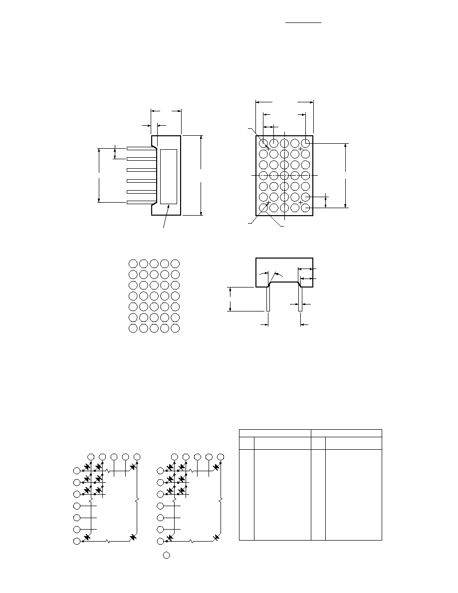
Package Dimensions
Internal Circuit Diagram
1
3
10
7
8
12
11
2
9
4
5
6
COLUMN
1
2
3
4
5
1
2
3
4
5
6
7
COMMON ANODE ROW
ROW
4
3
7
9
12
1
2
11
10
8
5
6
COLUMN
1
2
3
4
5
1
2
3
4
5
6
7
COMMON CATHODE ROW
ROW
COMMON ROW ANODE
COMMON ROW CATHODE
PIN
HDSP-701E/711E/
701G/711G/701A/711A
PIN
HDSP-703E/713E/
703G/713G/703A/713A
1
COLUMN 1 CATHODE
2
ROW 3 ANODE
3
COLUMN 2 CATHODE
4
ROW 5 ANODE
5
ROW 6 ANODE
6
ROW 7 ANODE
7
COLUMN 4 CATHODE
8
COLUMN 5 CATHODE
9
ROW 4 ANODE
10
COLUMN 3 CATHODE
11
ROW 2 ANODE
12
ROW 1 ANODE
1
ROW 1 CATHODE
2
ROW 2 CATHODE
3
COLUMN 2 ANODE
4
COLUMN 1 ANODE
5
ROW 6 CATHODE
6
ROW 7 CATHODE
7
COLUMN 3 ANODE
8
ROW 5 CATHODE
9
COLUMN 4 ANODE
10
ROW 4 CATHODE
11
ROW 3 CATHODE
12
COLUMN 5 ANODE
x = ROW OR COLUMN NUMBER, x = PIN NUMBER
NOTES:
1. ALL DIMENSIONS IN MILLIMETERS (INCHES).
2. UNLESS OTHERWISE STATED, TOLERANCE IS ± 0.25 mm (0.010).
3. FOR GREEN ONLY.
2.54
(0.10)
17.78
(0.70)
MAX.
35 ≠
1.9 (0.075)
15.24 (0.600)
12.7 (0.50)
MAX.
PIN 6
PIN 1
6.3
(0.25)
5.1 ± 0.5 (0.201)
7.62 (0.03)
1.3 (0.05)
12.7 (0.50)
PART NO.
2.54
(0.10)
10.16 (0.40)
2.54 (0.10)
8 ≠ 2.5 (0.098)
8 ≠ 3 (0.118)
12 ≠
0.5 (0.02)
8 ≠ 21.8∞
ROW
COL
1
1
2
3
4
5
2
3
4
5
6
7

3
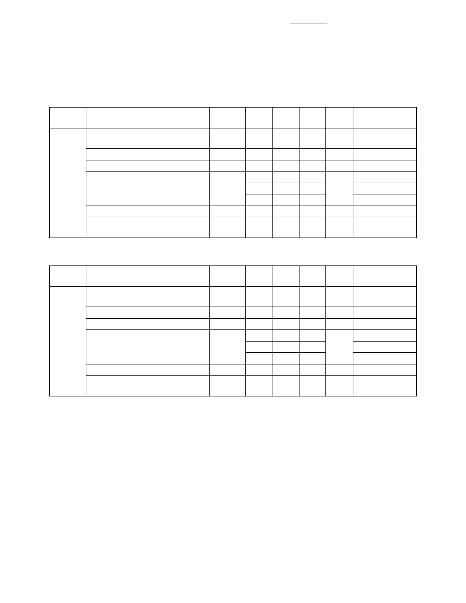
Optical/Electrical Characteristics at T
A
= 25
∞
C
High Efficiency Red
Devices
Test
HDSP-
Parameter
Symbol
Min.
Typ.
Max. Units
Conditions
Luminous Intensity/Dot
I
V
1.289
2.500
mcd
I
F
= 50 mA,
(Digit Average)
[1]
20% Duty Factor
Peak Wavelength
PEAK
632
nm
I
F
= 20 mA
Dominant Wavelength
[2]
d
622
nm
I
F
= 20 mA
Forward Voltage
V
F
3.40
V
I
F
= 50 mA
2.05
2.50
I
F
= 20 mA
1.60
I
F
= 5 mA
Reverse Voltage
[3]
V
R
5
V
I
R
= 100
µ
A
Luminous Intensity
V-M
2:1
I
F
= 50 mA
Matching Ratio
20% Duty Factor
701E
711E
703E
713E
Absolute Maximum Ratings at T
A
= 25
∞
C
HER
AlGaAs
Green
HDSP-701E/
HDSP-701A/
HDSP-701G/
Parameter
711E/703E/
703A/711A/
711G/703G/
713E
713A
713G
Units
Average Power per Dot
[1]
75
75
75
mW
Peak Forward Current per Dot
[1,2]
90
125
90
mA
(1/10 Duty Cycle, 0.1 ms Pulse Width)
Average Forward Current per Dot
[1]
23
23
[3]
15
[2]
mA
Reverse Voltage per Dot
5
5
5
V
Operating Temperature
≠40 to +85
≠40 to +85
≠40 to +85
∞
C
Storage Temperature
≠40 to +85
≠40 to +85
≠40 to + 85
∞
C
Wave Soldering Temperature for 3 seconds
[3]
250
250
250
∞
C
(1.6 mm [0.063 in.] below Body)
Notes:
1. Do not exceed maximum average current per dot.
2. Derate above 35
∞
C at 0.2 mA/
∞
C.
3. Not recommended to be soldered more than 2 times. Minimum interval between solderings is 15 minutes. Total soldering time not
to exceed 5 seconds.
4
Notes:
1. The digits are categorized for luminous intensity. The intensity category is designated by a letter on the side of the package.
2. The dominant wavelength, d, is derived from the CIE chromaticity diagram and represents the single wavelength which defines the
color of the device.
3. Typical specification for reference only. Do not exceed absolute maximum ratings.
AlGaAs
Devices
Test
HDSP-
Parameter
Symbol
Min.
Typ.
Max. Units
Conditions
Luminous Intensity/Dot
I
V
1.55
2.10
mcd
I
F
= 10 mA,
(Digit Average)
[1]
20% Duty Factor
Peak Wavelength
PEAK
660
nm
I
F
= 20 mA
Dominant Wavelength
[2]
d
643
nm
I
F
= 20 mA
Forward Voltage
V
F
1.8
2.0
V
I
F
= 20 mA
2.0
I
F
= 10 mA
1.5
I
F
= 5 mA
Reverse Voltage
[3]
V
R
5
V
I
R
= 100
µ
A
Luminous Intensity
V-M
1.5:1
I
F
= 10 mA
Matching Ratio
20% Duty Factor
701A
711A
703A
713A
Optical/Electrical Characteristics at T
A
= 25
∞
C, continued
Green
Devices
Test
HDSP-
Parameter
Symbol
Min.
Typ.
Max. Units
Conditions
Luminous Intensity/Dot
I
V
0.96
2.50
mcd
I
F
= 50 mA,
(Digit Average)
[1]
20% Duty Factor
Peak Wavelength
PEAK
568
nm
I
F
= 20 mA
Dominant Wavelength
[2]
d
573
nm
I
F
= 20 mA
Forward Voltage
V
F
3.40
V
I
F
= 50 mA
1.80
2.25
2.60
I
F
= 20 mA
1.60
I
F
= 5 mA
Reverse Voltage
[3]
V
R
5
V
I
R
= 100
µ
A
Luminous Intensity
V-M
2:1
I
F
= 50 mA
Matching Ratio
20% Duty Factor
701G
711G
703G
713G

5
Figure 1. Maximum Allowable Average Current
Per Dot vs. Ambient Temperature.
Figure 2. Forward Current vs. Forward Voltage.
Figure 3. Relative Luminous Intensity vs.
DC Forward Current.
Figure 4. Relative Efficiency (Luminous Intensity
Per Unit Current Per Dot) vs. Peak Current Per Dot.
I DC
≠
MAXIMUM DC CURRENT PER SEGMENT
≠
mA
0
0
TA ≠ AMBIENT TEMPERATURE ≠ ∞C
20
80
100
35
15
60
40
GREEN, HER
5
10
20
25
30
AlGaAs
I F
≠
FORWARD CURRENT PER SEGMENT
≠
mA
1
0
VF ≠ FORWARD VOLTAGE ≠ V
90
70
60
30
10
3
5
80
50
20
2
4
40
HER
GREEN
AlGaAs
RELATIVE LUMINOUS INTENSITY
(NORMALIZED AT 20 mA)
0
0
IF ≠ DC FORWARD CURRENT ≠ mA
4.0
3.0
2.5
1.5
0.5
20
40
3.5
2.0
1.0
10
30
GREEN, HER
5
15
25
35
AlGaAs
V
≠
RELATIVE EFFICIENCY
(NORMALIZED TO/AT 10 mA PER SEGMENT)
0
0.8
IPEAK ≠ PEAK FORWARD CURRENT
PER SEGMENT ≠ mA
90
20
70 80
100
1.4
1.3
1.2
1.1
1.0
0.9
60
50
40
30
10
RED
GREEN
AlGaAs