Description
The 18:88 and 88:88 0.56" Four
Digit Seven Segment Displays
have surface painted in neutral
gray for enhanced on/off
contrast. All devices are available
in either common anode or
common cathode configuration
with untinted segments.
Agilent HDSP-B0xE
18:88 and 88:88 0.56" Four Digit GaP
HER Seven Segment Display
Data Sheet
Features
· Excellent appearance
· Evenly illuminated segments
· Gray face for optimum on/off
contrast
· Choice of colors: HER
· Choice of character size:
0.56 inch
2
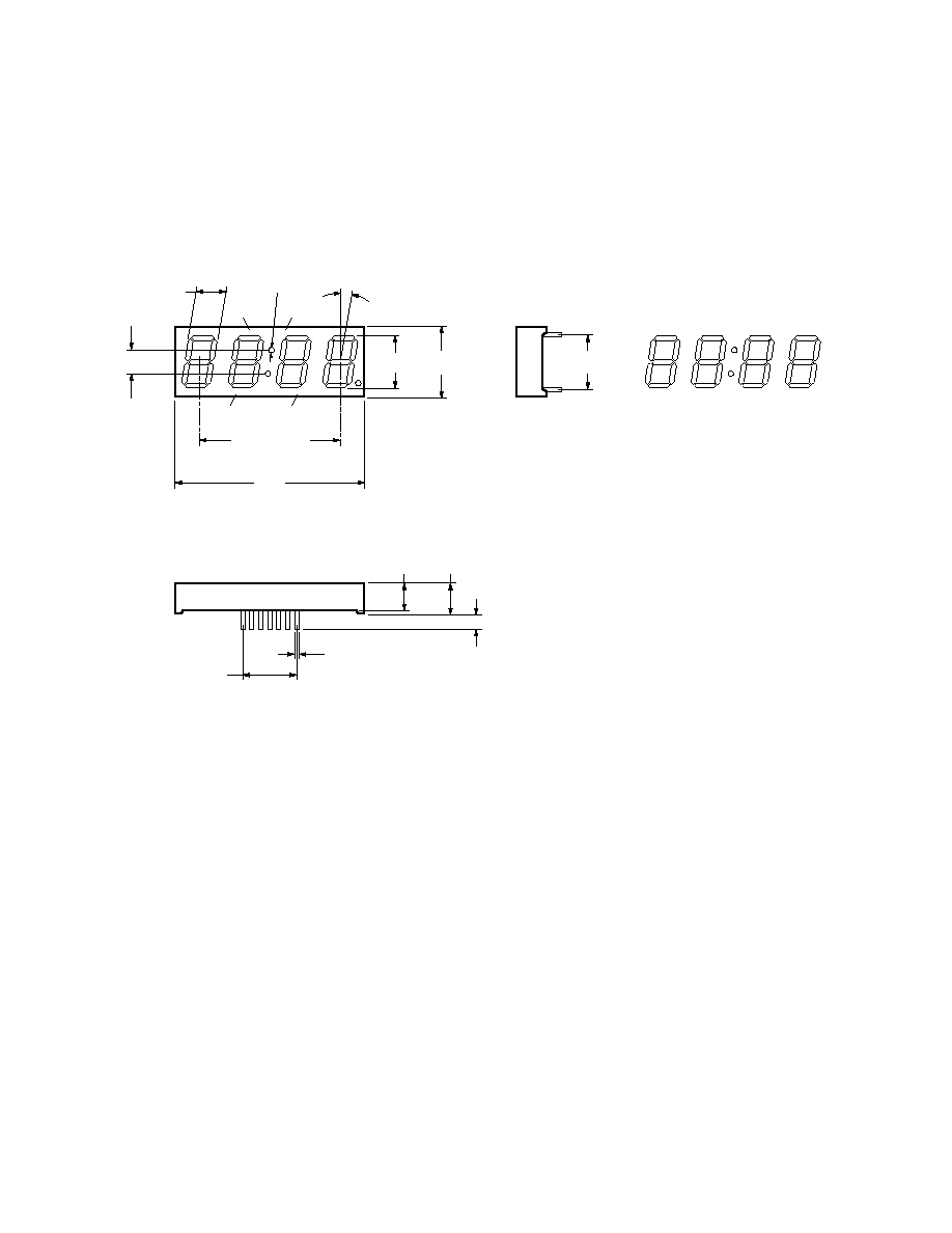
Package Dimensions
88:88 0.56" Four Digit Display
7.80
(0.307)
10.00°
19.10
(0.752)
12.7 x 3 = 38.10
(1.500)
FRONT SIDE
PIN 1
2
1.70
(0.067)
14.22
(0.560)
51.20
(2.016)
8.00
(0.315)
4.00
(0.157)
2.54 x 6 = 15.24
(0.600)
0.50
(0.020)
15.24
(0.600)
RIGHT SIDE
BOTTOM SIDE
A
A
A
D
D
D
C
F
E
F
E
F
E
B
C
B
C
B
C
G
G
G
DP3
DP2
6.00
(0.236)
+
+
+
+
PIN 7
PIN 12
PIN 8
7.00
(0.276)
DIGIT 2
DIGIT 3
DIGIT 4
DIGIT 1
A
F
E
B
G
D
NOTE:
ALL DIMENSIONS ARE IN MILLIMETERS (INCHES).
UNLESS OTHERWISE STATED, TOLERANCES ARE ± 0.25 mm.

3
Package Dimensions
18:88 0.56" Four Digit Display
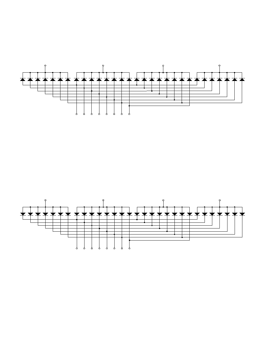
Pin Configuration
Function
Pin
HDSP-B01E/B03E
HDSP-B02E/B04E
1
Anode E
Cathode E
2
Anode D
Cathode D
3
Anode DP
Cathode DP
4
Anode C
Cathode C
5
Anode G
Cathode G
6
Digit 4 Common Cathode
Digit 4 Common Anode
7
Anode B
Cathode B
8
Digit 3 Common Cathode
Digit 3 Common Anode
9
Digit 2 Common Cathode
Digit 2 Common Anode
10
Anode F
Cathode F
11
Anode A
Cathode A
12
Digit 1 Common Cathode
Digit 1 Common Anode
7.80
(0.307)
10.00°
19.10
(0.752)
12.7 x 3 = 38.10
(1.500)
FRONT SIDE
PIN 1
2
1.70
(0.067)
14.22
(0.560)
51.20
(2.016)
8.00
(0.315)
4.00
(0.157)
2.54 x 6 = 15.24
(0.600)
0.50
(0.020)
15.24
(0.600)
RIGHT SIDE
BOTTOM SIDE
A
A
A
D
D
D
B
C
F
E
F
E
F
E
B
C
B
C
B
C
G
G
G
DP3
DP2
6.00
(0.236)
+
+
+
+
PIN 7
PIN 12
PIN 8
7.00
(0.276)
DIGIT 2
DIGIT 3
DIGIT 4
DIGIT 1
NOTE:
ALL DIMENSIONS ARE IN MILLIMETERS (INCHES).
UNLESS OTHERWISE STATED, TOLERANCES ARE ± 0.25 mm.