
Agilent HDSP-B42G, HDSP-B47G
18:88 0.56" Four Digit Seven Segment
Displays
Data Sheet
Features
∑ Excellent appearance
∑ Slim font design
∑ Mitered corners, evenly
illuminated segments
∑ Gray face for optimum on/off
contrast
∑ Choice of colors: green
∑ Choice of character size: 0.56 inch
∑ Characterized for luminous
intensity
Description
The 18:88 0.56" Four Digit Seven
Segment Displays incorporates a
new slim font character design. This
slim font features narrow width,
specially mitered segments to give a
fuller appearance to the illuminated
character. Faces of these displays
are painted a neutral gray for
enhanced on/off contrast.
All devices are available in either
common anode or common cathode
configuration with tinted green
segments.
Devices
Green
Description
HDSP-B42G
4 Digit, Common Anode, Tinted Green, 0.56" Display
HDSP-B47G
4 Digit, Common Cathode, Tinted Green, 0.56" Display

3
Absolute Maximum Ratings
Description
Green
Units
Average Power per Segment or DP
65
mW
Peak Forward Current per Segment or DP
100
mA
DC Forward Current per Segment or DP
25
mA
Operating Temperature Range
≠40 to +105
∞C
Storage Temperature Range
≠40 to +105
∞C
Reverse Voltage per Segment or DP
3
V
Wavesoldering Temperature for 3 seconds 1.59 mm below body
250
∞C
Note:
1. Derate above 40∞C at 0.33 mA/∞C for Green.
Electrical/Optical Characteristics at T
A
= 25∞C
Device Series
Parameter
Symbol
Min.
Typ.
Max.
Units
Test Conditions
HDSP-B42G/
Luminous Intensity/
I
V
2.000
3.200
mcd
I
F
= 10 mA
HDSP-B47G
Segment (Digit
Average)
Forward Voltage/
V
F
2.20
2.50
V
I
F
= 20 mA
Segment or DP
Peak Wavelength
PEAK
565
nm
I
F
= 20 mA
Dominant Wavelength
d
570
nm
I
F
= 20 mA
Reverse Current
I
R
100
µA
V
R
= 5 V
Notes:
1. Typical specification for reference only. Do not exceed absolute maximum ratings.
2. The dominant wavelength,
, is derived from the CIE chromaticity diagram and is that single wavelength which defines the color of the device.
Internal Circuit Diagram (Common Cathode)
Internal Circuit Diagram (Common Anode)
DIGIT 1
12
DIGIT 2
9
DIGIT 3
8
DIGIT 4
6
A
11
B
7
C
4
D
2
E
1
F
10
G
5
DP
3
B
C
DIGIT 1
12
DIGIT 2
9
DIGIT 3
8
DIGIT 4
6
A
11
B
7
C
4
D
2
E
1
F
10
G
5
DP
3
B
C
Contrast Enhancement
For information on contrast
enhancement, please see
Application Note 1015.
Soldering/Cleaning
Cleaning agents from the ketone
family (acetone, methyl ethyl
ketone, etc.) and from the chlori-
nated hydrocarbon family (meth-
ylene chloride, trichloroethylene,
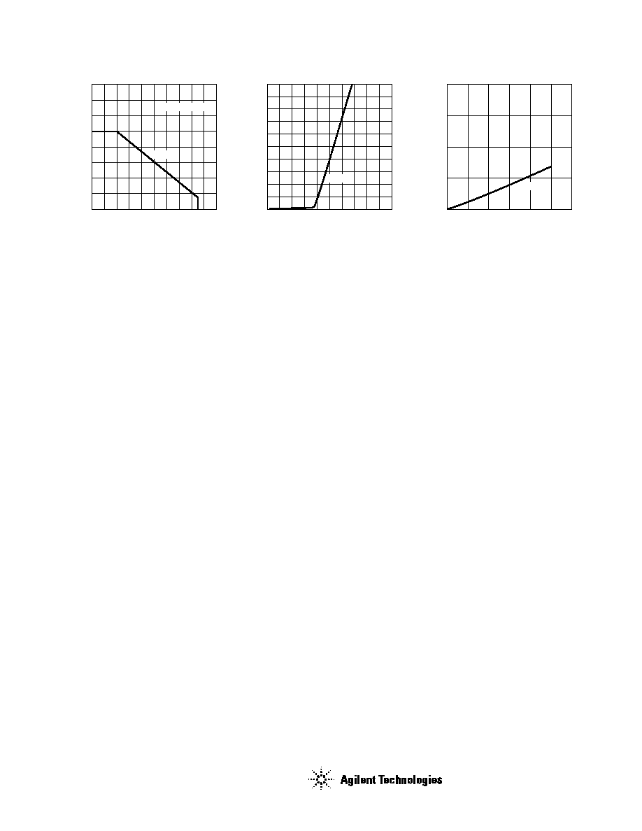
Figure 1. Maximum allowable DC current vs.
ambient temperature.
Figure 2. Forward current vs. forward
voltage.
Figure 3. Relative luminous intensity vs. DC
forward current.
I DC
≠
MAXIMUM DC CURRENT PER SEGMENT
≠
mA
20
0
TA ≠ AMBIENT TEMPERATURE ≠ ∞C
30
90
120
40
30
70
50
GREEN
10
20
5
15
25
35
40
60
80
100 110
R
J-A = 770∞C/W
I F
≠
FORWARD CURRENT PER SEGMENT
≠
mA
0
0
VF ≠ FORWARD VOLTAGE ≠ V
100
50
3
5
70
20
1
4
30
GREEN
2
80
10
40
60
90
RELATIVE LUMINOUS INTENSITY
(NORMALIZED TO 1 AT 10 mA FOR GREEN)
0
0
IF ≠ DC FORWARD CURRENT ≠ mA
8
6
4
2
20
10
30
GREEN
5
15
25
www.agilent.com/semiconduc-
tors
For product information and a complete list of
distributors, please go to our web site.
For technical assistance call:
Americas/Canada: +1 (800) 235-0312 or
(916) 788-6763
Europe: +49 (0) 6441 92460
China: 10800 650 0017
Hong Kong: (+65) 6756 2394
India, Australia, New Zealand: (+65) 6755 1939
Japan: (+81 3) 3335-8152(Domestic/
International), or 0120-61-1280(Domestic Only)
Korea: (+65) 6755 1989
Singapore, Malaysia, Vietnam, Thailand,
Philippines, Indonesia: (+65) 6755 2044
Taiwan: (+65) 6755 1843
Data subject to change.
Copyright © 2004 Agilent Technologies, Inc.
June 30, 2004
5988-4820EN
carbon tetrachloride, etc.) are not
recommended for cleaning LED
parts. All of these various
solvents attack or dissolve the
encapsulating epoxies used to
form the package of plastic LED
parts.
For information on soldering
LEDs, please refer to Application
Note 1027.
