ChipFind - документация

Электронный компонент: HDSP-B66Z-GF000

Скачать:  PDF   ZIP
Agilent HDSP-S6xE, HDSP-S6xG,
HDSP-B6xZ Series 32.9 mm (1.3 inch)
General Purpose 5 x 8 Dot Matrix
Alphanumeric Displays
Data Sheet
Description
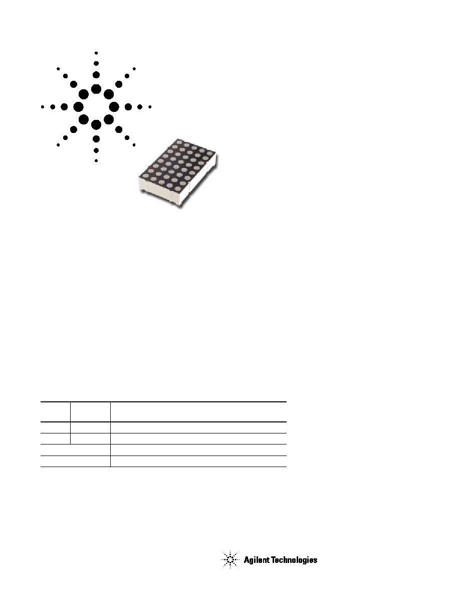
These displays have a 32.9 mm
(1.3 inch) character height. The
devices are available in either
common row anode or common row
cathode configurations. The
displays come in only black face
paint and are available in a choice
of GaP Red (HER) or GaP Green
colors. The Bi-color display consists
of HER and green colors.
Features
5 x 8 Dot matrix font
X-Y stackable
Pin-out
28.3 mm (1.114 in.) Dual-In-Line
(DIP) leads on 2.54 mm (0.1 in.)
centers
Choice of colors
Single color: red or green
Bi-color: red and green
Face paint color: black
Design flexibility
Common row anode or
common row cathode
Categorized for luminous intensity
Green categorized for color
Applications
Suitable for indoor use
Not recommended for industrial
applications, i.e. operating
temperature requirements
exceeding 85
C or below 35
C
Extreme temperature cycling not
recommended
[1]
These parts are subjected to Out-
going Quality Assurance (OQA)
inspection with an AQL of
0.065% for functional and visual/
cosmetic defects.
Devices
GaP Red
GaP Green
HDSP-
HDSP-
Description
S61E
S61G
32.9 mm Black Surface Common Row Anode
S66E
S66G
32.9 mm Black Surface Common Row Cathode
B61Z
32.9 mm Black Surface Bi-Color Common Row Anode
B66Z
32.9 mm Black Surface Bi-Color Common Row Cathode
Note:
1. For details, please contact your local Agilent components sales office or an authorized distributor.
2
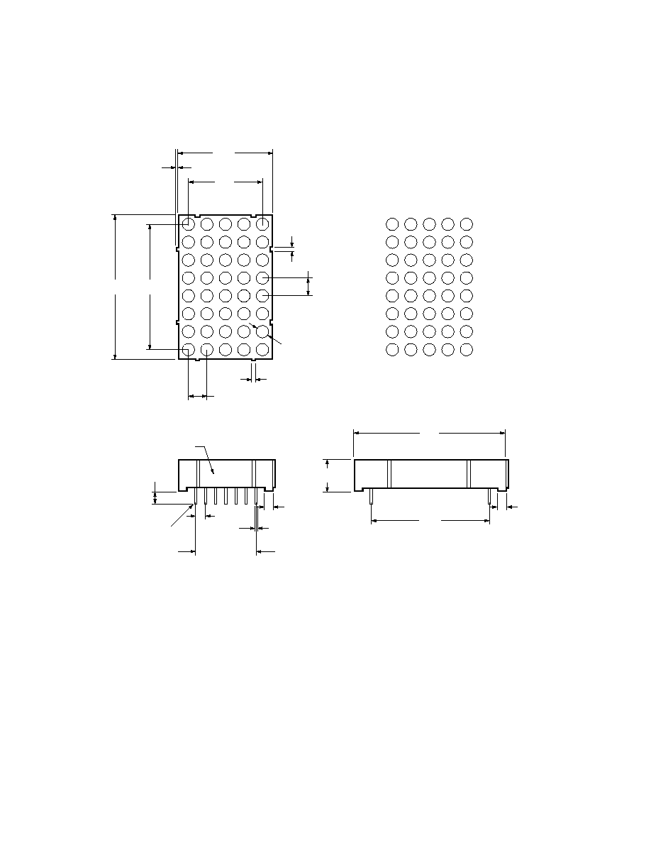
Package Dimensions
(Single Color)
18.40
(0.724)
32.20
(1.268)
23.40
(0.921)
ROW
COL
1
2
3
4
5
6
7
1
2
3
4
5
2.54 x 6 = 15.24
(0.1 x 6 = 0.6)
8.00
(0.315)
TOLERANCE: 0.25 mm UNLESS OTHERWISE STATED.
4.60
(0.181)
1.30
(0.051)
2.54
(0.10)
PART NO.
0.51
(0.020)
28.30
(1.114)
3.26 0.50
(0.128)
37.40
(1.472)
8
37.40
(1.472)
1.20
(0.047)
PIN 1
2.15
(0.085)
2.20
(0.087)
4.60
(0.181)
0.40
(0.016)
3.00 (0.118)
3
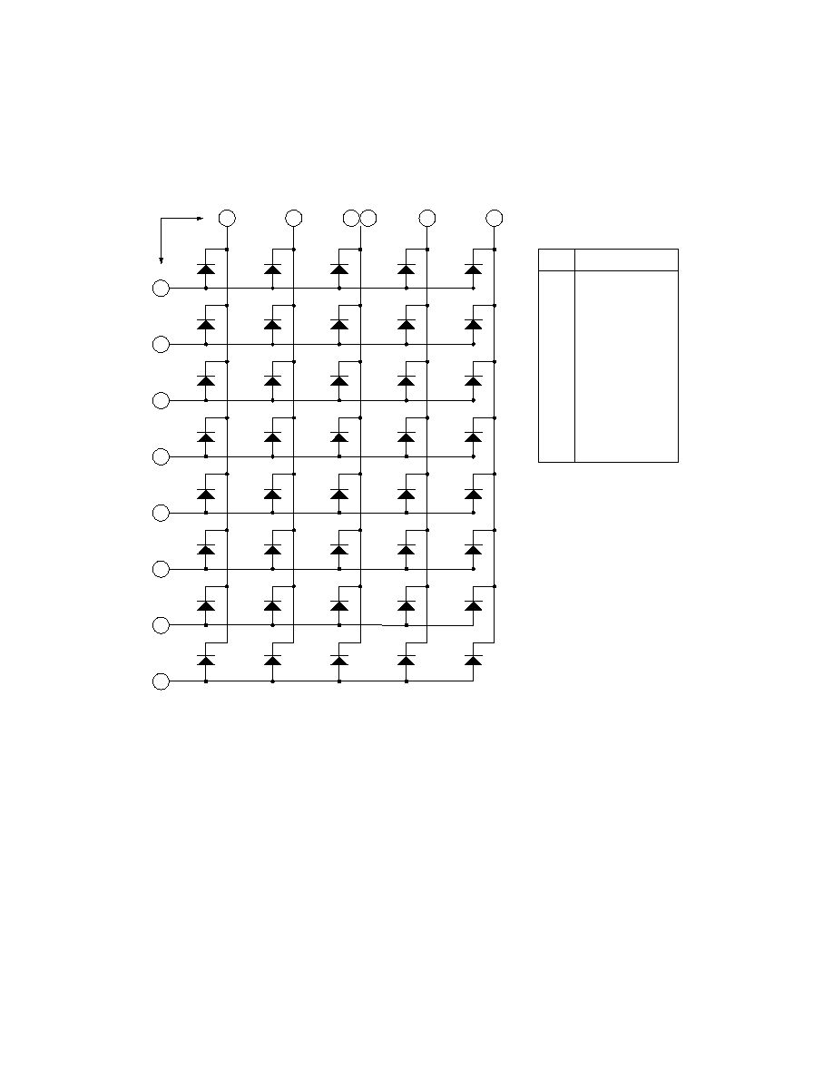
Internal Circuit Diagram
Common Row Anode (Single Color)
PIN NO.
FUNCTION
1
ANODE ROW 6
2
ANODE ROW 8
3
CATHODE COLUMN 2
4
CATHODE COLUMN 3
5
ANODE ROW 5
6
CATHODE COLUMN 5
7
ANODE ROW 7
8
ANODE ROW 3
9
ANODE ROW 1
10
CATHODE COLUMN 4
11
CATHODE COLUMN 3
12
ANODE ROW 4
13
CATHODE COLUMN 1
14
ANODE ROW 2
4
9
10
6
3
4
5
3
2
13
1
14
8
12
5
1
7
2
1
2
3
4
5
6
7
8
11
PIN
COLUMN
ROW
4
Internal Circuit Diagram
Common Row Cathode (Single Color)
PIN NO.
FUNCTION
1
CATHODE ROW 6
2
CATHODE ROW 8
3
ANODE COLUMN 2
4
ANODE COLUMN 3
5
CATHODE ROW 5
6
ANODE COLUMN 5
7
CATHODE ROW 7
8
CATHODE ROW 3
9
CATHODE ROW 1
10
ANODE COLUMN 4
11
ANODE COLUMN 3
12
CATHODE ROW 4
13
ANODE COLUMN 1
14
CATHODE ROW 2
11
9
10
6
3
4
5
3
2
13
1
14
8
12
5
1
7
2
1
2
3
4
5
6
7
8
4
PIN
COLUMN
ROW
5
Package Dimensions
(Bi-Color)
18.40
(0.724)
23.40
(0.921)
PIN 1
0.51 (0.020)
32.20
(1.268)
1.20 (0.047)
1.30
(0.051)
37.40
(1.472)
2.00 x 8 = 16.00
(0.079 x 8 = 0.630)
ROW
COL
1
2
3
4
5
6
7
1
2
3
4
5
8
8.00
(0.315)
28.30
(1.114)
3.26 0.50
(0.128)
37.40
(1.472)
23.40
(0.921)
2.00
(0.079)
3.00 (0.118)
4.60
(0.181)
0.40
(0.016)
4.60
(0.181)
2.15
(0.085)
2.20
(0.087)
TOLERANCE: 0.25 mm UNLESS OTHERWISE STATED.
PART NO.