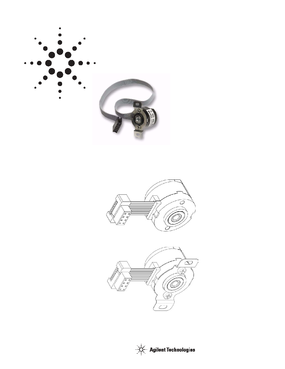
Description
The HEDL- 64XX series are high
performance, cost effective, two-
channel optical incremental
housed encoders with optional
index pulse. These encoders
emphasize high reliability, high
resolution and easy assembly. The
HEDL- 64XX housed encoders use
transmissive technology to sense
rotary position. This sensor
consists of an LED light source, a
photodetector IC and line driver.
The outputs of the HEDL- 64XX
encoders are 2 square waves in
quadrature and and an optional
gated index pulse. These encoders
may be quickly and easily
mounted to a motor.
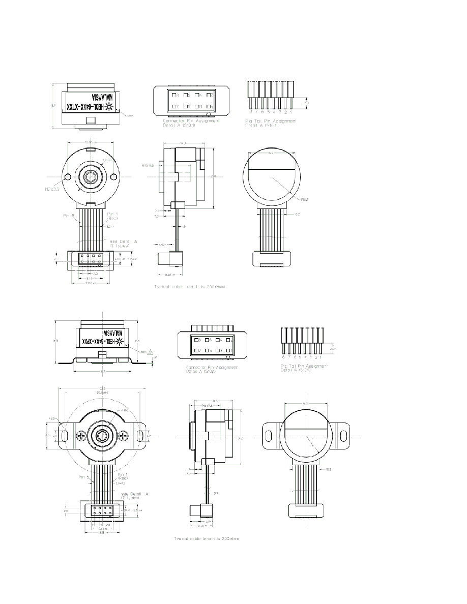
Available Styles
Threaded Hole Version
Coupling Plate Version
HEDL- 64XX Series Optical
Incremental Housed Encoders
Data Sheet
Features
∑ Two channel quadrature output
with optional index pulse
∑ Quick and easy assembly
∑ Cost-effective
∑ Small form factor
∑ IP50
∑ Resolutions up to 512 Counts Per
Revolution
∑ -25
∞C to 90∞ operating temperature
∑ Built-in RS 422 differential line
driver
∑ Hub available in 2,3 and 4 mm shaft
sizes.
∑ Coupling plate or threaded mount
mounting options available

3
Theory of Operation
The HEDL- 64XX translates
rotary motion of a shaft into a
two or three channel digital
output. The HEDL- 64XX series
has four key parts: a single light
emitting diode (LED) light
source, a photodetector IC with
a set of uniquely configured
photodiodes , a line drive IC
and a pair of lenses. The lens
over the LED focuses light onto
the codewheel. As the codewheel
rotates, an alternating pattern of
light and dark corresponding to
the pattern of the codewheel
falls upon the photodiodes.
This light is used to produce
internal signals A and A', and B
and B'.
As part of this "push- pull"
detector system, these signals
are fed through comparators and
line driver that are part of the
signal processing circuitry to
produce the final outputs for
channels A and B and index.
Definitions
Count (N): For rotary motion,
the number of bar and window
pairs or counts per
revolution(CPR) of the
codewheel. For linear motion,
the number of bar and window
pairs per unit length (lines per
inch[LPI] or lines per mm
[LPmm]).
One Cycle(C): 360 electrical
degree(
∞
e), 1 bar and window
pair.
One Shaft Rotation: 360
mechanical degrees, N cycles
(rotary motion only).
Line Density: The number of
reflective and non- reflective
pairs per unit length, expressed
as either lines per inch(LPI) or
lines per mm (LPmm).
Cycle error(
C):: An indication
of cycle uniformity. The
difference between an observed
shaft angle which gives rise to
one electrical cycle and the
nominal angular increment of 1/
N of a revolution
LENS
LED
Vcc
Gnd
Ch A
Ch A
Ch B
Ch B
I
I
RESISTOR
PHOTODIODE
SIGNAL
PROCESSING
CIRCUITY
CODEWHEEL
Pulse Width (P): The number of
the electrical degrees that an
output is high during one cycle,
nominally 180
∞
e or 1/2 a cycle.
Pulse Width Error(
P): The
deviation in electrical degrees of
the pulse width from its ideal
value of 180
∞
e.
State Width (S): The number of
the electrical degrees between a
transition in the output of the
channel B. There are 4 states
per cycle, each nominally 90
∞
e.
State Width Error (
S): The
deviation in electrical degrees of
each state width from its ideal
value of 90
∞
e.
Phase (f): The number of
electrical degrees between the
center of the high state on the
channel A and the center of the
high state of channel B. This
value is nominally 90
∞
e.
Phase error (
f): The deviation
in electrical degrees of the phase
from its ideal value of 90
∞
e.
Position error (
q):: The
normalized angular difference
between the actual shaft position
and the position indicated by
the encoder cycle count.
Index Pulse Width (Po): The
number of electrical degrees that
an index is high during one full
shaft rotation. This value is
nominally 90∞e or º cycle.
4
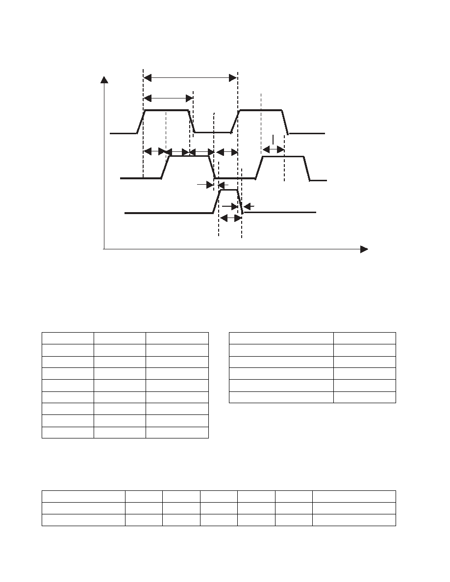
Output Waveforms
Direction of Motor Rotation
When the codewheel rotates in the clockwise direction (top view), channel A will lead channel B. If
the codewheel rotates in the counterclockwise direction, channel B will lead channel A.
Recommended Operating Conditions
Pin Assignment
Absolute Maximum Ratings
Pin
Signal
Description
Storage Temperature
-40
∞C to 100∞C
PIN 1
Ch A
Digital output
Operating Temperature
-25
∞C to 90∞C
PIN 2
Ch A'
Digital output
Supply Voltage
4.5 V to 5.5 V
PIN 3
Ground
Ground
Output Voltage
-0.5 V to 5.5V
PIN 4
Ch B
Digital output
Output Current per Channel
-2.0 mA to 25 mA
PIN 5
Ch B'
Digital output
Frequency
100 kHz
PIN 6
Vcc
Input voltage
Note s
rpm = frequency * 60 / cpr
Absolute Maximum Rating are those values beyond which the
safety of the device cannot be guaranteed. They are not meant
to imply that the device should be operated at these limits. The
table "Recommended Operating Conditions and
Characteristics" provides conditions for actual device
operation.
PIN 7
Index
Digital output
PIN 8
Index'
Digital output
Parameter
Symbol
Min.
Typical
Max.
Units
Notes
Temperature
T
A
0
25
90
∞C
Supply Voltage
V
CC
4.5
5.0
5.5
Volts
Amplitude
Channel A
Channel B
Index
s1
s2
s3
s4
C
P
o
P
0
t
2
t
1
Codewheel Rotation
5
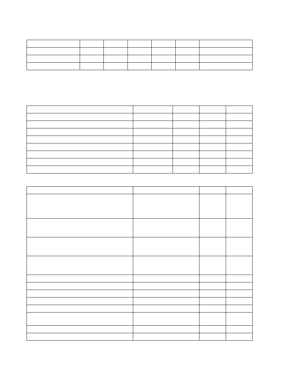
Electrical Characteristics
(over recommended operating conditions Typically at 25
o
C)
Notes
This device meets the ESD ratings below:
Class C per EIA/JESD22-A115-A (MM)
Class 1C per JESD22-A114-B (HBM)
Encoding Characteristics
Mechanical Characteristics (refer to page 2 and 3 for details)
Parameter
Symbol
Min.
Typical
Max.
Units
Notes
Supply Current
I
CC
40
65
mA
High level Output Voltage
V
OH
2.4
V
I
OH
= -2 mA min.
Low level Output Voltage
V
OL
0.2
V
I
OL
= 25 mA max
Parameter
Symbol
Typical
Max.
Units
Pulse Width Error
P
7
70
∞e
State Width Error
S
15
60
∞e
Phase Error
Df
15
60
∞e
Position Error
DQ
40
120
arcmin
Cycle Error
C
10
45
∞e
Index Pulse Width
P
o
90
120
∞e
Index rise time after Ch B fall
t
1
500
800
ns
Index fall time after Ch A rise
t
2
150
500
ns
Parameter
Dimension/Details
Tolerance
Units
Recommended Motor Shaft Diameters
Adhesive Mount
(recommended mounting glue type is Hernon 823
anaerobic glue or equivalent)
2, 3, 4
+/-.01
(+/-.0004)
mm
(in)
Allowable Motor Shaft Length
Coupling plate
Threaded mount
11.6 max
11.0 max
mm
Bolt Circle Diameter :
Coupling plate
Threaded mount
28.6
15.90
+/-0.1
+/-0.05
mm
Mounting Screw Size:
Coupling plate
Threaded mount
M2
M2x 3.5
mm
Max axial load
0.3
kgf
Max radial load
0.3
kgf
Bearing life (based on the above loading)
2 x 10
10
rev
Unit weight
22
gm
Sealing (per IEC 529)
IP50
Humidity
98% RH max
Non condensing
Vibration (per IEC 68-2-27)
20g @ 10 Hz ~ 500 Hz
Shock (per IEC 68-2-27)
30 g @ 11ms