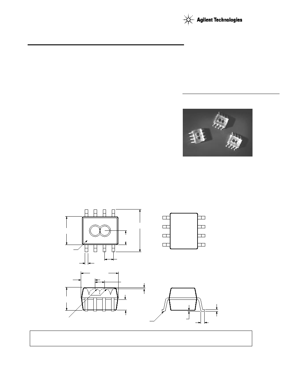
6.2 ± 0.20
(0.244 ± 0.008)
1.270
(0.050)
1
2
3
4
8
7
6
5
TYP.
3.94 ± 0.13 *
(0.155 ± 0.005)
1.97
(0.078)
REF.
REF.
0.38 ± 0.08
(0.016 ± 0.003)
3.18 ± 0.13
(0.125 ± 0.005)
5.08 ± 0.13 *
(0.200 ± 0.005)
1.40 ± 0.02
(0.055 ± 0.001)
1.52
(0.06)
REF.
PIN ONE
INDICATOR
LOCATION
0.025
(0.001)
MIN.
1.84
(0.072)
REF.
0.700 R
(0.0276)
REF.
LEAD COPLANARITY ± 0.051
(0.002)
0.23 ± 0.03
(0.009 ± 0.001)
0.59
(0.023)
MIN.
0.18 ± 0.08
(0.007 ± 0.003)
1
2
3
4
8
7
6
5
NC
GND
A
V
CC
V
LED
NC
B
GND
NOTES:
*FLASH MAY ADD 0.38 (0.015) MAX.
AT PARTING LINE.
DIMENSIONS IN MILLIMETERS (INCHES).
FOR THE 1CHANNEL HEDR-8010, PIN 6
IS CONSIDERED NC.
Reflective Optical Surface
Mount Encoders
Technical Data
HEDR-8000 Series
HEDR-8100 Series
HEDR-8010 Series
Features
∑ Reflective Technology
∑ Surface Mount SO-8 Package
∑ Two Channel Quadrature
Outputs for Direction
Sensing
∑ Two Encoding Resolution
Options:
≠ 2.76 ≠ 2.95 Lines/mm
(70 ≠ 75 Lines/inch)
≠ 5.91 Lines/mm
(150 Lines/inch)
Description
The HEDR-8000/8100 Series
encoders use reflective technol-
ogy to sense rotary or linear
position. This sensor consists of
an LED light source and a
photodetector IC in a single SO-8
surface mount package. When
used with a reflective codewheel
or codestrip, this device can sense
rotary or linear position.
ESD WARNING: NORMAL HANDLING PRECAUTIONS SHOULD BE TAKEN TO AVOID STATIC
DISCHARGE.
Outline Drawing
NOTE: HEDR-8000 series
products are classified as MSL
Level 3.
2
VLED
GND
VCC
CH A
CH B
GND
SIGNAL
PROCESSING
CIRCUITRY
R
CODEWHEEL
OR
CODESTRIP
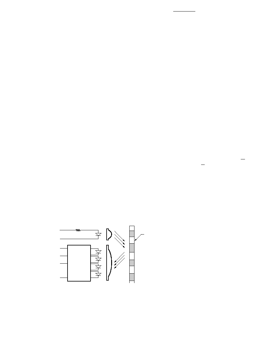
Block Diagram
The reflective surface mount
optical encoders provide two
square wave outputs in quadra-
ture for count and direction
information. These TTL
compatible outputs correspond to
the alternating reflective/non-
reflective pattern of the
codewheel or codestrip.
The HEDR-8000/8100 series
encoders can be used over a
range of codewheel and codestrip
resolutions. The HEDR-8000/
8100 reflective encoder can
operate from 2.76 to 2.95 lines
per mm (70 to 75 lines per inch).
The HEDR-8100 can be used with
a codewheel or codestrip with
150 lines per inch (5.91 lines
per mm).
Applications
The HEDR-8000/8100 series
provides two channel motion
sensing at a very low cost, making
it ideal for high volume
applications. Its small size and
surface mount capability make it
ideal for printers, copiers, card
readers, and consumer product
applications.
Note: Agilent Technologies
encoders are not recommended
for use in safety critical
applications. Eg. ABS braking
systems, power steering, life
support systems and critical care
medical equipment. Please
contact sales representative if
more clarification is needed.
Theory of Operation
The HEDR-8000/8100 series
combines an emitter and a
detector in a single surface mount
SO-8 package. When used with a
codewheel or codestrip, the
reflective sensors translates
rotary or linear motion into a two
channel digital output.
As seen in the block diagram, the
HEDR-8000/8100 series has three
key parts: a single light emitting
diode (LED) light source, a
photodetector IC with a set of
uniquely configured photodiodes,
and a pair of lenses molded into
the package. The lens over the
LED focuses light onto the
codewheel or codestrip. Light is
either reflected or not reflected
back to the lens over the
photodetector IC.
As the codewheel rotates or
codestrip passes by, an alternat-
ing pattern of light and dark
corresponding to the pattern of
the codewheel falls upon the
photodiodes. This light is used to
produce internal signals A and A,
and B and B. As part of this
"push-pull" detector system, these
signals are fed through compara-
tors to produce the final outputs
for channels A and B.

3
State Width (S): The number of
electrical degrees between a
transition in the output of channel
A and the neighboring transition in
the output of channel B. There are
4 states per cycle, each nominally
90
∞
e.
State Width Error (
S): The
deviation in electrical degrees of
each state width from its ideal
value of 90
∞
e.
Phase (
): The number of
electrical degrees between the
center of the high state on channel
A and the center of the high state
on channel B. This value is
nominally 90
∞
e.
Phase Error (
): The deviation
in electrical degrees of the phase
from its ideal value of 90
∞
e.
Direction of Rotation: When the
codewheel or codestrip moves in
the direction from pin 1 to pin 4,
as viewed when looking down on
the lenses, channel B will lead
channel A. If the codewheel or
codestrip moves in the opposite
direction, channel A will lead
channel B.
Optical Radius (Rop): For rotary
motion, the distance from the
codewheel's center of rotation to
the center line connecting the two
lenses of the encoder.
Gap (G): The distance from the
top of the package to the surface of
the reflective codewheel or
codestrip.
Specular Reflectance (R
f
): a
measure of a surface's reflective
finish. This is quantified by the
amount of light reflected when hit
with an incident beam. A device
called a scatterometer is used to
quantify specular reflectance on a
percent scale. (Contact factory for
more information.)
Radial and Tangential
Misalignment Error (E
R
, E
T
):
For rotary motion, mechanical
misalignment in the radial and
tangential directions relative to the
codewheel.
Angular Misalignment Error
(E
A
): angular misalignment of the
sensor in relation to the tangential
direction. This applies for both
rotary and linear motion.
Output Waveforms
HEDR-8000
SHAFT
CODEWHEEL
RADIAL
TANGENTIAL
HEDR-8000
SHAFT
CODEWHEEL
EA
S1
S2
S3
S4
P
C
CH. B
CH. A
ALL FOUR STATES (S1 TO S4)
ARE MAINTAINED.
CODEWHEEL ROTATION OR LINEAR MOVEMENT
AMPLITUDE
Definitions
Count (N): For rotary motion,
the number of bar and window
pairs or counts per revolution
(CPR) of the codewheel. For
linear motion, the number of bar
and window pairs per unit length
(lines per inch [LPI] or lines per
mm [LPmm]).
One Cycle (C): 360 electrical
degrees (
∞
e), 1 bar and window
pair.
One Shaft Rotation: 360
mechanical degrees, N cycles
(rotary motion only).
Line Density: The number of
reflective and non-reflective pairs
per unit length, expressed as
either lines per inch (LPI) or lines
per mm (LPmm).
Pulse Width (P): The number of
electrical degrees that an output
is high during one cycle,
nominally 180
∞
e or 1/2 a cycle.
Pulse Width Error (
P): The
deviation in electrical degrees of
the pulse width from its ideal
value of 180
∞
e.

4
Encoding Characteristics
Encoding Characteristics Over the Recommended Operating Conditions and Mounting Conditions.
Parameter
Symbol
Typical
Maximum
Units
Notes
Pulse Width Error
P
15
55
∞
e
HEDR-8010
Pulse Width Error (Ch.A,Ch.B)
P
16
75
∞
e
HEDR-8100
Phase Error
10
60
∞
e
HEDR-8100
Pulse Width Error (Ch.A,Ch.B)
P
15,25
55,75
∞
e
HEDR-8000
Phase Error
12
60
∞
e
HEDR-8000
Recommended Operating Conditions
Parameter
Symbol
Min.
Typ.
Max.
Units
Notes
Temperature
T
A
-10
85
∞
C
Supply Voltage
V
CC
4.5
5.0
5.5
Volts
Ripple < 100 mVp-p
LED Current
I
LED
13
15
18
mA
See "Current Limiting
Resistor for LED"
Load Capacitance
C
L
100
pF
2.7 K
Pull-Up
Count Frequency
f
15
kHz
Velocity (rpm) x N/60
Radial Misalignment
E
R
±
0.38
mm
(
±
0.015)
(in.)
Tangential Misalignment
E
T
±
0.38
mm
(
±
0.015)
(in.)
Angular Misalignment
E
A
0
±
1.5
deg.
Codewheel or Codestrip
G
1.52
2.03
2.54
mm
HEDR-8000
Gap
(0.060) (0.080)
(0.100)
(in.)
HEDR-8010
G
1.02
1.52
2.03
mm
HEDR-8100
(0.040) (0.060)
(0.080)
(in.)
Codewheel or Codestrip
R
f
60%
As Measured on TMA
Specular Reflectance
µ
scan Scope (see Note 1)
Codewheel/Codestrip Tilt
C
T
0
1
deg.
Codewheel/Codestrip
LPmm
2.76
2.95
lines/mm
HEDR-8000
Resolution
(LPI)
(70)
(75)
(lines/in.)
HEDR-8010
LPmm
5.91
lines/mm
HEDR-8100
(LPI)
150
(lines/in.)
Notes:
1. Contact factory for more information regarding measurement of specular reflectance.
Absolute Maximum Ratings
Storage Temperature, T
S
-40
∞
C to 85
∞
C
Operating Temperature, T
A
-10
∞
C to 85
∞
C
Supply Voltage, V
CC
-0.5 V to 7 V
Output Voltage, V
O
-0.5 V to V
CC
Output Current per Channel, I
OUT
-1.0 mA to 5 mA
Note: Exposure to extreme light intensity (such as from flashbulbs or spotlights) can
cause permanent damage to device.
Note:
Typical Value was obtained at typical condition. Maximums were obtained over all range of recommended operating condition and
mounting condition.

5
Parameter
Symbol
Min.
Max.
Units
Notes
Window/Bar Ratio
Ww/Wb
0.9
1.1
Specular Reflectance
R
f
60
85
Reflective Bars
≠
10
Non-reflective Bars
Line Density
LPmm
2.76
2.95
lines/mm
HEDR-8000
(LPI)
(70)
(75)
(lines/inch)
HEDR-8010
LPmm
5.91
7.09
lines/mm
HEDR-8100
(LPI)
(150)
(180)
(lines/inch)
Window Length
Lw
1.80
2.31
mm (inches)
mm
(0.071)
(0.091)
(inches)
Contact factory for further information on compatible codewheel and codestrips.
Electrical Characteristics
Electrical Characteristics Over Recommended Operating Conditions. Typical Values at 25
∞
C.
Parameter
Symbol
Min.
Typ.
Max.
Units
Notes
Supply Current
I
CC
2.2
5.0
mA
High Level Output Voltage
V
OH
2.4
V
I
OH
= -40
µ
A min.
Low Level Output Voltage
V
OL
0.4
V
I
OL
= 3.86 mA
Rise Time
t
r
150
200
ns
C
L
= 25 pF
R
L
= 2.7 K
Fall Time
t
f
50
60
ns
Current Limiting Resistor
for LED
A resistor to limit current to the
LED is required. The recom-
mended value is 220
(
±
10%)
and should be placed in series
between the 5 V supply and pin 8
of the device (V
LED
). This will
result in an LED current of
approximately 15 mA.
ROP
W
b
W
w
L
w
L
w
W
w
W
b
Recommended Codewheel and Codestrip Characteristics