
Agilent HEDS-9710, HEDS-9711
200 lpi Analog Output
Small Optical Encoder Modules
Data Sheet
Description
The HEDS-9710/HEDS-9711 series
is a high performance, low cost,
optical incremental encoder mod-
ule. When operated in conjunction
with either a codewheel or
codestrip, this module detects ro-
tary or linear position. The encoder
module consists of a lensed LED
source and a detector IC enclosed
in a small C-shaped plastic package.
Due to a highly collimated light
source and a unique photodetector
array, the module is extremely tol-
erant to mounting misalignment.
The two-channel analog outputs and
5 V supply input are accessed
through four solder-plated leads
located on 2.54 mm (0.1 inch)
centers.
The standard HEDS-9710/HEDS-
9711 is designed for use with an
Features
∑ Small size
∑ Multiple mounting options
∑ 200 lpi resolution
∑ Linear and rotary options available
∑ Insensitive to radial and axial play
∑ 15
∞
C to 45
∞
C operating temperature
∑ Two-channel analog output
∑ Single 5 V supply
∑ Wave solderable
ESD WARNING: NORMAL PRECAUTIONS SHOULD BE TAKEN TO AVOID STATIC DISCHARGE.
appropriate optical radius
codewheel, or linear codestrip.
Please contact the factory for
more information.
Applications
The HEDS-9710/HEDS-9711
provides sophisticated motion
detection at a low cost, making
closed-loop control very cost-
effective. Typical applications
include printers, plotters, copiers,
and office automation equipment.
Note: Agilent Technologies
encoders are not recommended
for use in safety critical
applications, eg., ABS braking
systems, power steering, life
support systems, and critical care
medical equipment. Please contact
sales representative if more
clarification is needed.
Theory of Operation
The HEDS-9710/HEDS-9711 is a
C-shaped emitter/detector mod-
ule. Coupled with a codewheel, it
translates rotary motion into a
two-channel analog output.
Coupled with a codestrip, it trans-
lates linear motion into analog
outputs.

2
The module contains a single
Light Emitting Diode (LED) as its
light source. The light is colli-
mated into a parallel beam by
means of a single lens located
directly over the LED. Opposite
the emitter is the integrated de-
tector circuit. This IC consists of
multiple sets of photodetectors
and the signal processing cir-
cuitry necessary to produce the
analog waveforms.
The codewheel/codestrip moves
between the emitter and detector,
causing the light beam to be in-
terrupted by the pattern of spaces
and bars on the codewheel/
codestrip. The photodiodes which
detect these interruptions are
arranged in a pattern that corre-
sponds to the radius and count
density of the codewheel/
codestrip. These detectors are
also spaced such that a light
period on one pair of detectors
corresponds to a dark period on
the adjacent pair of detectors.
The photodiode outputs are fed
through the signal processing
circuitry, which produces the
final outputs for channels A and
B. Due to this integrated phasing
technique, the analog output of
channel A is in quadrature with
channel B (90 degrees out of
phase).
Package Dimensions
See HEDS-9700 datasheet for
package outline drawings.
Definitions
Count (N): The number of bar
and window pairs or Counts Per
Revolution (CPR) of the code-
wheel, or the number of Lines Per
Inch (LPI) of the codestrip.
1 Shaft Rotation = 360 mechanical
degrees
= N cycles
1 cycle (c) = 360 electrical
degrees (
∞
e)
= 1 bar and window pair
Pulse Width (P): The number of
electrical degrees that an output
is high during one cycle. This
value is nominally 180
∞
e or 1/2
cycle.
Pulse Width Error (
P): The
deviation, in electrical degrees, of
the pulse width from its ideal
value of 180
∞
e.
State Width (S): The number of
electrical degrees between a
transition in the output of channel
A and the neighboring transition
in the output of channel B. There
are four states per cycle, each
nominally 90
∞
e.
State Width Error (
S): The
deviation, in electrical degrees, of
each state width from its ideal
value of 90
∞
e.
Phase (
): The number of elec-
trical degrees between the center
of the high state of channel A and
the center of the high state of
channel B. This value is nomi-
nally 90
∞
e for quadrature output.
Phase Error (
): The devia-
tion of the phase from its ideal
value of 90
∞
e.
Direction of Rotation: When
the codewheel rotates counter-
clockwise, as viewed looking
down on the module (so the
marking is visible), channel A will
lead channel B. If the codewheel
rotates in the opposite direction,
channel B will lead channel A.
Optical Radius (R
OP
): The
distance from the codewheel's
center of rotation to the optical
center (O.C.) of the encoder
module.
Mounting Position (R
M
):
Distance from Motor Shaft center
of rotation to center of Alignment
Tab receiving hole.
Absolute Maximum Ratings
Parameter
Symbol
Min.
Max.
Units
Notes
Storage Temperature
T
S
≠40
85
∞
C
Operating Temperature
T
A
15
45
∞
C
Supply Voltage
V
CC
≠0.5
7
V
Soldering Temperature
260
∞
C
t
5 sec.
Recommended Operating Conditions
Parameter
Symbol
Min.
Max.
Units
Notes
Temperature
T
15
45
Supply Voltage
V
CC
4.8
5.2
V
Ripple < 100 mV
p-p
Count Frequency
8
kHz
(Velocity (rpm) x N) 60
3
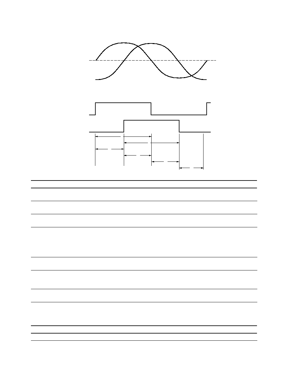
Waveform Definition
Iap
Ibp
Ibm
Iam
A
B
A
B
ANALOG
DIGITAL
P
P
S1
S2
S3
S4
Name
Paramenter
Definition
Label
Analog Peak
The absolute value in
µ
A of the magnitude of the
Iap, Ibp,
analog signal (i.e., one-sided reading).
Iam, Ibm
Analog Peak-to-Peak
Ipp
The peak-to-peak signal magnitude in
µ
A of the
Iapp
analog signal.
Ibpp
Analog Offset
Ioffset
The offset in
µ
A from the mid-point of the analog
peak-to-peak signal to the zero current point.
State Width
State Width
The number of electrical degrees between a transition
State 1
in channel A and the neighboring transition in channel B.
State 2
There are four states per cycle, each nominally 90
∞
e.
State 3
The transitions are determined by where the analog
State 4
signal crosses the Zero point.
State Width Error
State Width Error
The deviation, in electrical degrees, of each state width
from its ideal value of 90
∞
e.
Pulse Width
Pulse Width
The number of electrical degrees that an analog output
P
is greater than zero during one cycle. This value is
nominally 180
∞
e or 1/2 cycle.
Pulse Width Error
Pulse Width Error
The deviation, in electrical degrees, of each pulse width
from its ideal value of 180
∞
e.
Electrical Characteristics
Electrical Characteristics over Recommended Operating Range, Typical at 25
∞
C.
Parameter
Symbol
Min.
Typ.
Max.
Units
Notes
Supply Current
I
CC
17
40
mA

4
Encoding Characteristics
Encoding Characteristics over Recommended Operating Range and
Recommended Mounting Tolerances.
These characteristics do not include codewheel/codestrip contributions.
Units
Radial
microns
±
130
Tangential
microns
±
130
Gap
microns
50 ≠ 250
Temperature
∞
C
15 ≠ 45
O.R.
mm
18 ≠ Linear
CPR
count
900 ≠ Linear
Codewheel Slot/Spoke
ratio
0.9 ≠ 1.1
Min.
Max.
Ipp
µ
A
10
73
Ioffset
µ
A
≠4
+4
State Width Error
e
∞
≠40
+40
Pulse Width Error
e
∞
≠40
+40
Recommended Codewheel and Codestrip Characteristics
Parameter
Symbol
Min.
Max.
Units
Notes
Window/Bar Ratio
Ww/Wb
0.9
1.1
Window Length (Rotary)
Lw
1.80
2.30
mm
(0.071)
(0.091)
(inch)
Absolute Maximum Codewheel
Rc
Rop + 3.40
mm
Includes eccen≠
Radius (Rotary)
(Rop + 0.134)
(inch)
tricity errors
Center of Post to Inside
W1
1.04
mm
Edge of Window
(0.041)
(inch)
Center of Post to Outside
W2
0.76
mm
Edge of Window
(0.030)
(inch)
Center of Post to Inside Edge
L
3.60
mm
of Codestrip
(0.142)
(inch)

5
Analog Encoder Interface Circuit
IA-IN
VREF
I+
+
≠
C
R1
VA
IB-IN
VREF
I+
+
≠
C
R1
VB
VREF = 1.4 V ± 0.2 V (DC)
The circuit shown can be used to
convert the current output to a
voltage. Resistor value, R1, and
Capacitor, C, are specified to
attain required gain and low-pass
filtering, which are application
specific. The gain is chosen to
attain maximum output swing
and not clamp the op-amp. V
REF
should be set to 1.4 V
±
0.2 V.
A 0.1
µ
F bypass capacitor
(decoupling capacitor) is recom-
mended to be placed within 1 cm
of the encoder for optimal power
supply noise rejection. Outputs
are high impedance (typical 1
M ohm) and susceptible to EMI.
Ordering Information
HEDS-971
Lead Configurations
0 ≠ straight leads
1 ≠ bent leads
Resolutions
R ≠ 200 lpi
Option
Bracket Options
50
51