 | –≠–ª–µ–∫—Ç—Ä–æ–Ω–Ω—ã–π –∫–æ–º–ø–æ–Ω–µ–Ω—Ç: HFBR-24E6 | –°–∫–∞—á–∞—Ç—å:  PDF PDF  ZIP ZIP |
Transmitters and receivers are
directly compatible with popular
"industry-standard" connectors:
ST, SMA, SC and FC. They are
completely specified with
multiple fiber sizes; including
50/125
µ
m, 62.5/125
µ
m, 100/
140
µ
m, and 200
µ
m.
Complete evaluation kits are
available for ST product
offerings; including transmitter,
receiver, connectored cable, and
technical literature. In addition,
ST connectored cables are
available for evaluation.
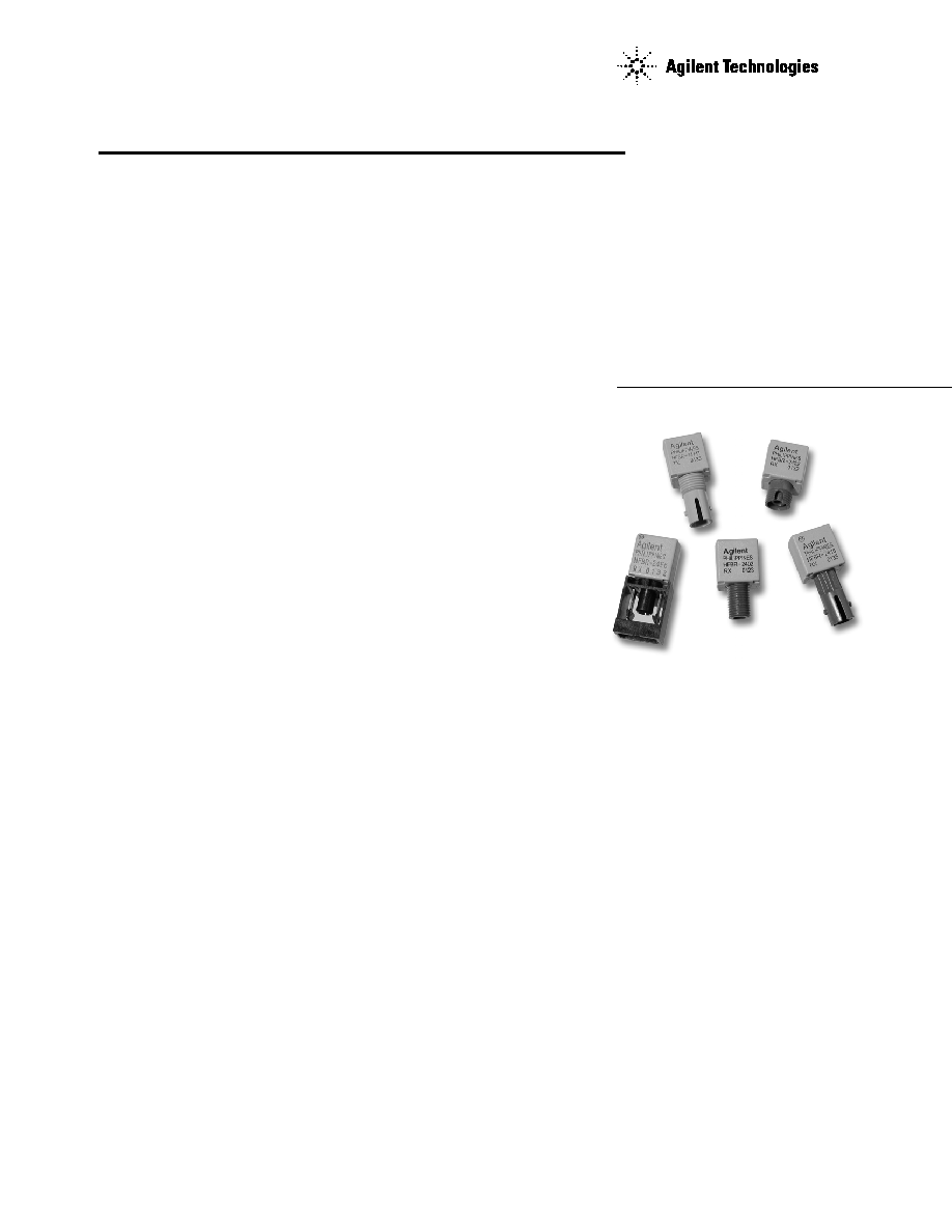
Low Cost, Miniature Fiber
Optic Components with ST
Æ
,
SMA, SC and FC Ports
Technical Data
HFBR-0400 Series
HFBR-14xx Transmitters
HFBR-24xx Receivers
Features
∑ Meets IEEE 802.3 Ethernet
and 802.5 Token Ring
Standards
∑ Low Cost Transmitters and
Receivers
∑ Choice of ST
Æ
, SMA, SC or
FC Ports
∑ 820 nm Wavelength
Technology
∑ Signal Rates up to 160
Megabaud
∑ Link Distances up to 2.7 km
∑ Specified with 50/125
µ
m,
62.5/125
µ
m, 100/140
µ
m,
and 200
µ
m HCS
Æ
Fiber
∑ Repeatable ST Connections
within 0.2 dB Typical
∑ Unique Optical Port Design
for Efficient Coupling
∑ Auto-Insertable and Wave
Solderable
∑ No Board Mounting Hard-
ware Required
∑ Wide Operating
Temperature Range
-40
∞
C to 85
∞
C
∑ AlGaAs Emitters 100%
Burn-In Ensures High
Reliability
∑ Conductive Port Option
Applications
∑ Local Area Networks
∑ Computer to Peripheral
Links
∑ Computer Monitor Links
∑ Digital Cross Connect Links
∑ Central Office Switch/PBX
Links
∑ Video Links
∑ Modems and Multiplexers
∑ Suitable for Tempest
Systems
∑ Industrial Control Links
Description
The HFBR-0400 Series of compo-
nents is designed to provide cost
effective, high performance fiber
optic communication links for
information systems and
industrial applications with link
distances of up to 2.7 kilometers.
With the HFBR-24X6, the 125
MHz analog receiver, data rates
of up to 160 megabaud are
attainable.
ST
Æ
is a registered trademark of AT&T.
HCS
Æ
is a registered trademark of the SpecTran Corporation.
2
LINK SELECTION GUIDE
Data Rate (MBd)
Distance (m)
Transmitter
Receiver
Fiber Size (
µ
m)
Evaluation Kit
5
1500
HFBR-14X2
HFBR-24X2
200 HCS
N/A
5
2000
HFBR-14X4
HFBR-24X2
62.5/125
HFBR-0410
20
2700
HFBR-14X4
HFBR-24X6
62.5/125
HFBR-0414
32
2200
HFBR-14X4
HFBR-24X6
62.5/125
HFBR-0414
55
1400
HFBR-14X4
HFBR-24X6
62.5/125
HFBR-0414
125
700
HFBR-14X4
HFBR-24X6
62.5/125
HFBR-0416
155
600
HFBR-14X4
HFBR-24X6
62.5/125
HFBR-0416
160
500
HFBR-14X4
HFBR-24X6
62.5/125
HFBR-0416
For additional information on specific links see the following individual link descriptions. Distances measured over temperature range
from 0 to 70
∞
C.
Applications Support
Guide
This section gives the designer
information necessary to use the
HFBR-0400 series components to
make a functional fiber-optic
transceiver. Agilent offers a wide
selection of evaluation kits for
hands-on experience with fiber-
optic products as well as a wide
Application Literature
Title
Description
HFBR-0400 Series
Transmitter & Receiver Reliability Data
Reliability Data
Application Bulletin 78
Low Cost Fiber Optic Links for Digital Applications up to 155 MBd
Application Note 1038
Complete Fiber Solutions for IEEE 802.3 FOIRL, 10Base-FB and 10 Base-FL
Application Note 1065
Complete Solutions for IEEE 802.5J Fiber-Optic Token Ring
Application Note 1073
HFBR-0319 Test Fixture for 1X9 Fiber Optic Transceivers
Application Note 1086
Optical Fiber Interconnections in Telecommunication Products
Application Note 1121
DC to 32 MBd Fiber-Optic Solutions
Application Note 1122
2 to 70 MBd Fiber-Optic Solutions
Application Note 1123
20 to 160 MBd Fiber-Optic Solutions
Application Note 1137 Generic Printed Circuit Layout Rules
range of application notes com-
plete with circuit diagrams and
board layouts. Furthermore,
Agilent's application support
group is always ready to assist
with any design consideration.
Available Options
HFBR-1402
HFBR-1414
HFBR-1404
HFBR-1414M
HFBR-1412
HFBR-1414T
HFBR-1412T
HFBR-1424
HFBR-1412TM
HFBR-2412TC
HFBR-14E4
HFBR-2416
HFBR-2402
HFBR-2416M
HFBR-2406
HFBR-2412
HFBR-2412T
HFBR-2416TC
HFBR-2422
HFBR-24E6
HFBR-2416T
HFBR-0400 Series Part Number Guide
HFBR X4XXaa
1 = Transmitter
Option T (Threaded Port Option)
2 = Receiver
Option C (Conductive Port Receiver Option)
Option M (Metal Port Option)
4 = 820 nm Transmitter and
Receiver Products
0 = SMA, Housed
1 = ST, Housed
2 = FC, Housed
E = SC, Housed
2 = Tx, Standard Power
4 = Tx, High Power
2 = Rx, 5 MBd, TTL Output
6 = Rx, 125 MHz, Analog Output

3
HFBR-0400 Series
Evaluation Kits
HFBR-0410 ST Evaluation Kit
Contains the following :
∑ One HFBR-1412 transmitter
∑ One HFBR-2412 five megabaud
TTL receiver
∑ Three meters of ST connec-
tored 62.5/125 (
µ
m fiber optic
cable with low cost plastic
ferrules.
∑ Related literature
HFBR-0414 ST Evaluation Kit
Includes additional components
to interface to the transmitter and
receiver as well as the PCB to
reduce design time.
Contains the following:
∑ One HFBR-1414T transmitter
∑ One HFBR-2416T receiver
∑ Three meters of ST connec-
tored 62.5/125
µ
m fiber optic
cable
∑ Printed circuit board
∑ ML-4622 CP Data Quantizer
∑ 74ACTllOOON LED Driver
∑ LT1016CN8 Comparator
∑ 4.7
µ
H Inductor
∑ Related literature
HFBR-0400 SMA Evaluation
Kit
Contains the following :
∑ One HFBR-1402 transmitter
∑ One HFBR-2402 five megabaud
TTL receiver
∑ Two meters of SMA
connectored 1000
µ
m plastic
optical fiber
∑ Related literature
HFBR-0416 Evaluation Kit
Contains the following:
∑ One fully assembled 1x9
transceiver board for 155 MBd
evaluation including:
-HFBR-1414 transmitter
-HFBR-2416 receiver
-circuitry
∑ Related literature
Package and Handling
Information
Package Information
All HFBR-0400 Series
transmitters and receivers are
housed in a low-cost, dual-inline
package that is made of high
strength, heat resistant, chem-
ically resistant, and UL 94V-O
flame retardant ULTEM
Æ
(plastic
(UL File #E121562). The
transmitters are easily identified
by the light grey color connector
port. The receivers are easily
identified by the dark grey color
connector port. (Black color for
conductive port.) The package is
designed for auto-insertion and
wave soldering so it is ideal for
high volume production
applications.
Handling and Design
Information
Each part comes with a protective
port cap or plug covering the
optics. These caps/plugs will vary
by port style. When soldering, it
is advisable to leave the protec-
tive cap on the unit to keep the
optics clean. Good system
performance requires clean port
optics and cable ferrules to avoid
obstructing the optical path.
Clean compressed air often is
sufficient to remove particles of
dirt; methanol on a cotton swab
also works well.
Recommended Chemicals for
Cleaning/Degreasing
HFBR-0400 Products
Alcohols: methyl, isopropyl,
isobutyl. Aliphatics: hexane,
heptane, Other: soap solution,
naphtha.
Do not use partially halogenated
hydrocarbons such as 1,1.1
trichloroethane, ketones such as
MEK, acetone, chloroform, ethyl
acetate, methylene dichloride,
phenol, methylene chloride, or
N-methylpyrolldone. Also, Agilent
does not recommend the use of
cleaners that use halogenated
hydrocarbons because of their
potential environmental harm.
Ultem
Æ
is a registered Trademark of the GE corporation.
4
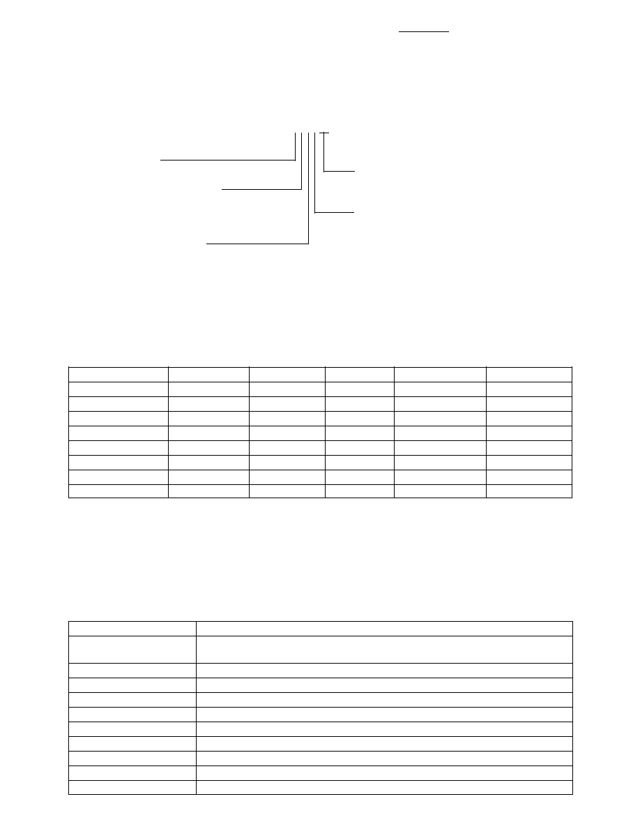
Mechanical Dimensions
SMA Port
HFBR-X40X
6.35
(0.25)
2.54
(0.10)
3.81
(0.15)
6.4
(0.25)
DIA.
12.7
(0.50)
12.7
(0.50)
22.2
(0.87)
5.1
(0.20)
10.2
(0.40)
3.6
(0.14)
1.27
(0.05)
2.54
(0.10)
PINS 1,4,5,8
0.51 X 0.38
(0.020 X 0.015)
PINS 2,3,6,7
0.46
(0.018)
DIA.
8
1
3
5
2
4
6
7
PIN NO. 1
INDICATOR
1/4 - 36 UNS 2A THREAD
Rx/Tx
COUNTRY OF
ORIGIN
A YYWW
HFBR-X40X
Mechanical Dimensions
ST Port
HFBR-X41X
8.2
(0.32)
Rx/Tx
COUNTRY OF
ORIGIN
A YYWW
HFBR-X41X
6.35
(0.25)
12.7
(0.50)
27.2
(1.07)
5.1
(0.20)
10.2
(0.40)
3.6
(0.14)
1.27
(0.05)
2.54
(0.10)
PINS 1,4,5,8
0.51 X 0.38
(0.020 X 0.015)
PINS 2,3,6,7
0.46
(0.018)
DIA.
8
1
3
5
2
4
6
7
PIN NO. 1
INDICATOR
2.54
(0.10)
3.81
(0.15)
DIA.
12.7
(0.50)
7.0
(0.28)
5
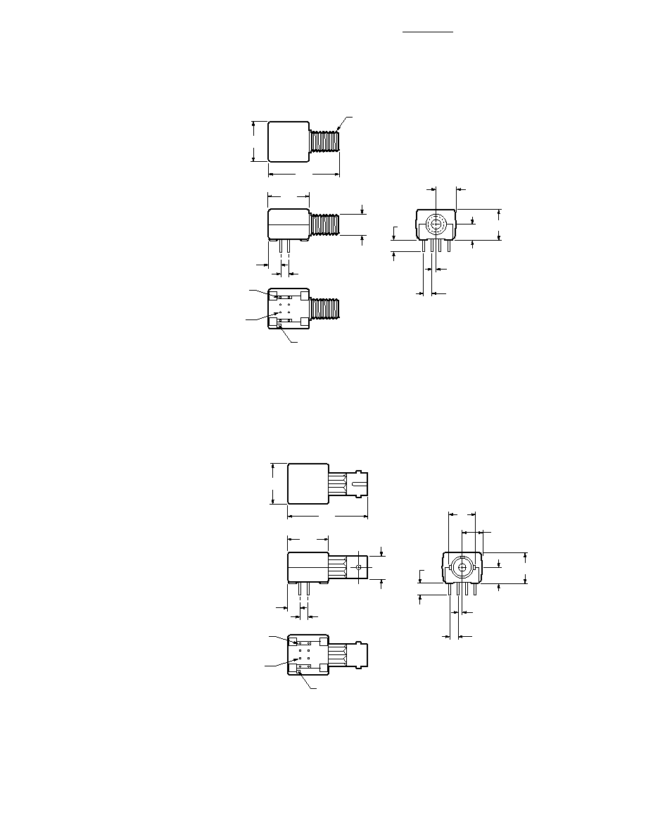
Mechanical Dimensions
Threaded ST Port
HFBR-X41XT
5.1
(0.20)
3/8 - 32 UNEF - 2A
Rx/Tx
COUNTRY OF
ORIGIN
A YYWW
HFBR-X41XT
8.4
(0.33)
6.35
(0.25)
12.7
(0.50)
27.2
(1.07)
5.1
(0.20)
10.2
(0.40)
3.6
(0.14)
1.27
(0.05)
2.54
(0.10)
PINS 1,4,5,8
0.51 X 0.38
(0.020 X 0.015)
PINS 2,3,6,7
0.46
(0.018)
DIA.
8
1
3
5
2
4
6
7
PIN NO. 1
INDICATOR
2.54
(0.10)
3.81
(0.15)
DIA.
12.7
(0.50)
7.1
(0.28)
DIA.
7.6
(0.30)
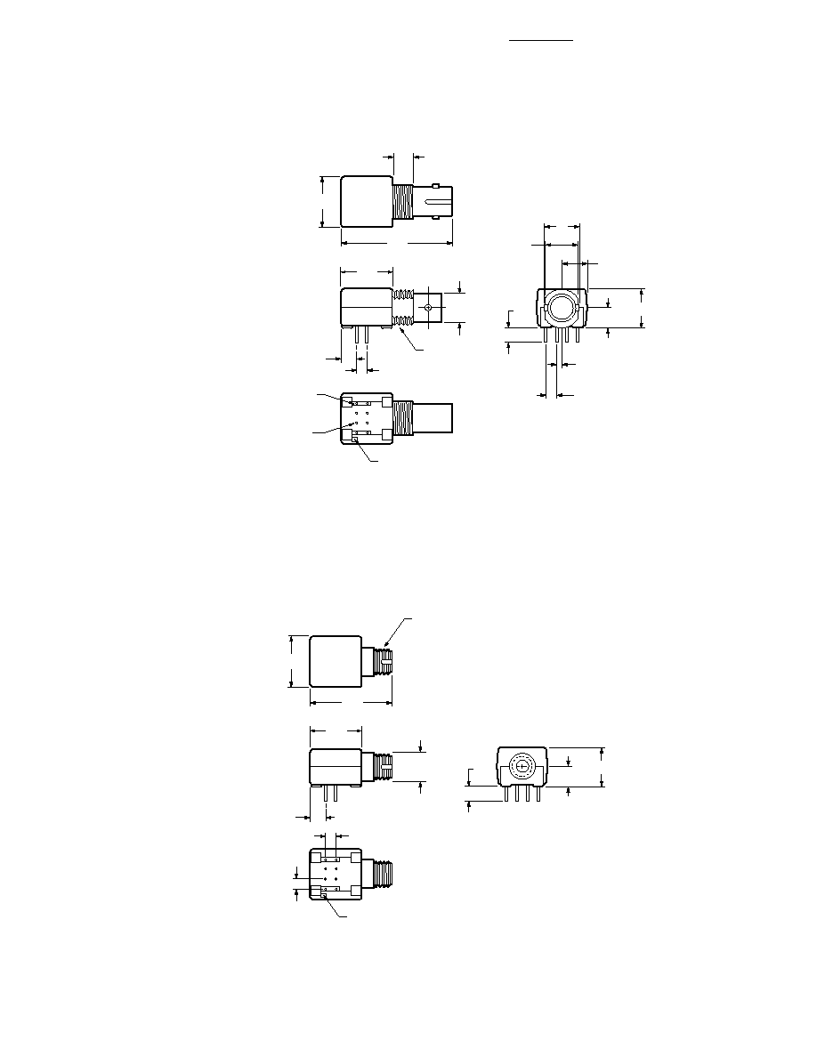
Mechanical Dimensions
FC Port
M8 x 0.75 6G
THREAD (METRIC)
Rx/Tx
COUNTRY OF
ORIGIN
A YYWW
HFBR-X42X
2.5
(0.10)
3.81
(0.15)
7.9
(0.31)
12.7
(0.50)
12.7
(0.50)
5.1
(0.20)
10.2
(0.40)
3.6
(0.14)
8
1
3
5
2
4
6
7
PIN NO. 1
INDICATOR
19.6
(0.77)
2.5
(0.10)
HFBR-X42X