 | –≠–ª–µ–∫—Ç—Ä–æ–Ω–Ω—ã–π –∫–æ–º–ø–æ–Ω–µ–Ω—Ç: HFBR-5602 | –°–∫–∞—á–∞—Ç—å:  PDF PDF  ZIP ZIP |
Document Outline
- Features
- Applications
- Related Products
- Description
- Serial Identification
- GBIC Serial ID Memory Contents
- Regulatory Compliance
- Table
- Electrostatic Discharge (ESD)
- Electromagnetic Interference (EMI)
- Immunity
- Eye Safety
- Outline Drawing
- CAUTION
- 20-Pin SCA-2 Host Connector Characteristics
- Short Wavelength GBIC: HFBR-5602
- Transmitter Section
- Receiver Section
- Eye Safety Design
- Absolute Maximum Ratings
- Recommended Operating Conditions
- Transceiver Electrical Characteristics
- Transmitter Electrical Characteristics
- Receiver Electrical Characteristics
- Transmitter Optical Characteristics
- Receiver Optical Characteristics
- Long Wavelength GBIC: HFCT-5612
- Transmitter Section
- Receiver Section
- Eye Safety Design
- Absolute Maximum Ratings
- Recommended Operating Conditions
- Transceiver Electrical Characteristics
- Transmitter Electrical Characteristics
- Receiver Electrical Characteristics
- Transmitter Optical Characteristics
- Receiver Optical Characteristics
Agilent HFBR-5602/HFCT-5612
Gigabit Interface Converters
(GBIC) for Fibre Channel
Data Sheet
Description
The HFBR-56xx/HFCT-56xx
family of interface converters
meet the Gigabit Interface
Converter specification Rev. 5.4.
The family provides a uniform
form factor for a wide variety of
standard connections to
transmission media. The
converters can be inserted or
removed from a host chassis
without removing power from the
host system.
The converters are suitable for
interconnections in the Fibre
Channel mass storage and data
transfer environment. The design
of these converters is also
practical for other high
performance, point-to-point
communication requiring gigabit
interconnections. Since the
converters are hot-pluggable, they
allow system configuration
changes or maintenance simply by
plugging in a different type of
converter.
Features
∑ Compliant with Gigabit Interface
Converter specification Rev. 5.4 (1)
∑ HFBR-5602 is compliant with ANSI
X3.297-1996 Fibre Channel Physical
Interface FC-PH-2 Revision 7.4
proposed specifications
∑ HFCT-5612 is compliant with ANSI
100-SM-LC-L Revision 2
enhancement to X3.297-1996
FC-PH-2 Revision 7.4
∑ Performance:
HFBR-5602:
300 m over 62.5/125 µm MMF
500 m over 50/125 µm MMF
HFCT-5612:
500 m with 50/125 µm MMF
500 m with 62.5/125 µm MMF
10 km with 9/125 µm SMF
∑ Horizontal or vertical installation
∑ AEL Laser Class 1 eye safe per
IEC 60825-1
∑ AEL Laser Class I eye safe per
US 21 CFR
∑ Hot-Pluggable
Applications
∑ Mass storage system I/O
∑ Computer system I/O
∑ High-speed peripheral interface
∑ High-speed switching systems
∑ Host adapter I/O
∑ RAID cabinets
Related Products
∑ 850 nm 1 x 9 VCSEL transceiver for
Fibre Channel applications
(HFBR-53D3)
∑ 1300 nm, 1 x 9 laser transceiver for
Fibre Channel applications
(HFCT-53D3)
∑ Physical layer ICs available for
optical or copper interface
(HDMP-1536A/46A)
∑ Versions of both 1 x 9 and GBIC
transceiver module for Gigabit
Ethernet
The mechanical and electrical
interfaces of these converters to
the host system are identical for
all implementations of the
converter regardless of external
media type. A 20-pin connector is
used to connect the converter to
the host system. Surge currents
are eliminated by using pin
sequencing at this connector and
a slow-start circuit. Two ground
tabs at this connector also make
contact before any other pins,
discharging possible component-
damaging static electricity. In
addition, the connector itself
performs a two-stage contact
sequence. Operational signals and
power supply ground make
contact in stage 1 while power
makes contact in stage 2.
The HFBR-5602 has been
developed with 850 nm short
wavelength VCSEL technology
while the HFCT-5612 is based on
1300 nm long wavelength Fabry
Perot laser technology.

2
The HFBR-5602 complies with
Annex E of the GBIC specification
Revision 5.4. In the Fibre Channel
environment, the HFBR-5602
achieves 300 m transmission
distance with 62.5 µm and 50 µm
multimode fibre.
The HFCT-5612 complies with
Annex C of the GBIC specification
Revision 5.4 and reaches 10 km
with 9/125 µm single mode fiber.
Both the HFBR-5602 and the
HFCT-5612 are Class 1 Eye Safe
laser devices.
Serial Identification
The HFBR-56xx and HFCT-5612
family complies with Annex D
(Module Definition 4) of the GBIC
specification Revision 5.4, which
defines the Serial Identification
Protocol.
Definition 4 specifies a serial
definition protocol. For this
definition, upon power up,
MOD_DEF(1:2) (Pins 5 and 6 on
the 20-pin connector) appear as
NC. Pin 4 is TTL ground. When the
host system detects this
condition, it activates the public
domain serial protocol. The
protocol uses the 2-wire serial
CMOS E
2
PROM protocol of the
ATMEL AT24C01A or similar.
The data transfer protocol and the
details of the mandatory and
vendor specific data structures
are defined in Annex D of the
GBIC specification Revision 5.4.
Regulatory Compliance
See the Regulatory Compliance
Table for the targeted typical and
measured performance for these
transceivers.
The overall equipment design will
determine the level it is able to be
certified to. These transceiver
performance targets are offered as
a figure of merit to assist the
designer in considering their use
in equipment designs.
Electrostatic Discharge (ESD)
There are two design cases in
which immunity to ESD damage is
important.
The first case is during handling of
the transceiver prior to inserting it
into the host system. It is
important to use normal ESD
handling precautions for ESD
sensitive devices. These
precautions include using
grounded wrist straps, work
benches, and floor mats in ESD
controlled areas.
The second case to consider is
static discharges during insertion
of the GBIC into the host system.
There are two guide tabs
integrated into the 20-pin
connector on the GBIC. These
guide tabs are connected to
circuit ground. When the GBIC is
inserted into the host system,
these tabs shall engage before any
of the connector pins. The mating
connector in the host system
should have its tabs connected to
circuit ground. This discharges
any stray static charges and
establishes a reference for the
power supplies that are sequenced
later.
Electromagnetic Interference (EMI)
Most equipment designs utilizing
these high-speed transceivers
from Agilent will be required to
meet the requirements of FCC in
the United States, CENELEC
EN55022 (CISPR 22) in Europe
and VCCI in Japan.
Immunity
Equipment utilizing these
transceivers will be subject to
radio-frequency electromagnetic
fields in some environments.
These transceivers have good
immunity to such fields due to
their shielded design.
Eye Safety
Laser-based GBIC transceivers
provide Class 1 (IEC 60825-1) and
Class I (US 21 CFR[J]) laser eye
safety by design. Agilent has
tested the current transceiver
design for compliance with the
requirements listed below under
normal operating conditions and
for compliance under single fault
conditions.
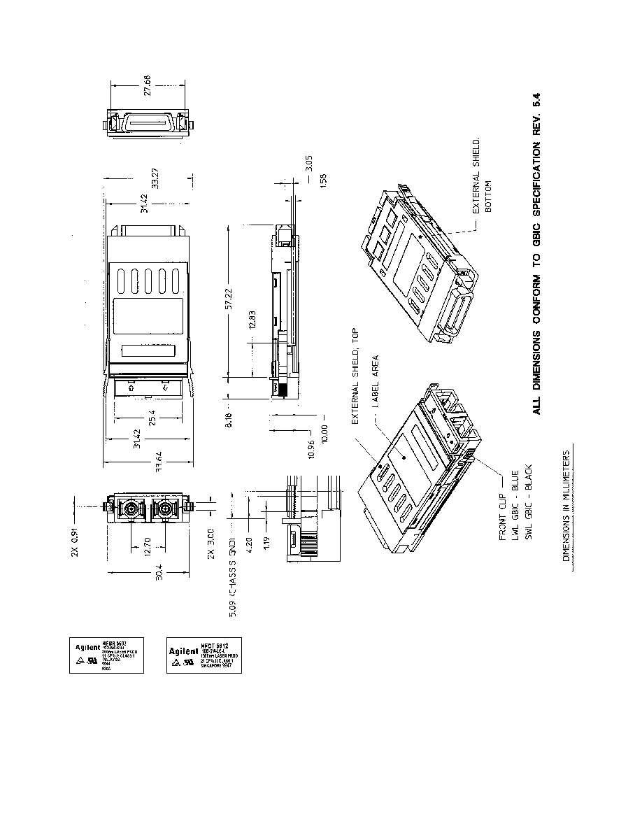
Outline Drawing
An outline drawing is shown in
Figure 1. More detailed drawings
are shown in Gigabit Interface
Converter specification Rev. 5.4.
CAUTION:
There are no user serviceable
parts nor any maintenance
required for the HFBR-56xx and
HFCT-56xx product family. All
adjustments are made at the
factory before shipment to our
customers. Tampering with or
modifying the performance of any
Agilent GBIC unit will result in
voided product warranty. It may
also result in improper operation
of the circuitry, and possible
overstress of the semiconductor
components. Device degradation
or product failure may result.

3
GBIC Serial ID Memory Contents - HFBR-5602
Note: Blanks in ASCII column are numeric values not ASCII characters.
Addr
Hex
ASCII
Addr
Hex
ASCII
Addr
Hex
ASCII
Addr
Hex
ASCII
0
1
40
48
H
68
39
9
96
20
1
5
41
46
F
69
38
8
97
20
2
1
42
42
B
70
30
0
98
20
3
0
43
52
R
71
36
6
99
20
4
0
44
2D
-
72
32
2
100
20
5
0
45
35
5
73
33
3
101
20
6
0
46
36
6
74
30
0
102
20
7
40
47
30
0
75
33
3
103
20
8
40
48
32
2
76
32
2
104
20
9
0C
49
20
77
39
9
105
20
10
1
50
20
78
33
3
106
20
11
1
51
20
79
36
6
107
20
12
0B
52
20
80
38
8
108
20
13
0
53
20
81
39
9
109
20
14
0
54
20
82
34
4
110
20
15
0
55
20
83
32
2
111
20
16
32
56
30
0
84
39
9
112
20
17
1E
57
30
0
85
38
8
113
20
18
0
58
30
0
86
30
0
114
20
19
0
59
30
0
87
36
6
115
20
20
41
A
60
0
88
32
2
116
20
21
47
G
61
0
89
33
3
117
20
22
49
I
62
0
90
30
0
118
20
23
4C
L
63
6
91
30
0
119
20
24
45
E
64
0
92
0
120
20
25
4E
N
65
1A
93
0
121
20
26
54
T
66
0
94
0
122
20
27
20
67
0
95
0
123
20
28
20
124
20
29
20
125
20
30
20
126
20
31
20
127
20
32
20
33
20
34
20
35
20
36
0
37
0
38
0
39
0

4
GBIC Serial ID Memory Contents - HFCT-5612
Note: Blanks in ASCII column are numeric values not ASCII characters.
Addr
Hex
ASCII
Addr
Hex
ASCII
Addr
Hex
ASCII
Addr
Hex
ASCII
0
1
40
48
H
68
39
9
96
20
1
3
41
46
F
69
38
8
97
20
2
1
42
43
C
70
30
0
98
20
3
0
43
54
T
71
36
6
99
20
4
0
44
2D
-
72
31
1
100
20
5
0
45
35
5
73
38
8
101
20
6
0
46
36
6
74
31
1
102
20
7
12
47
31
1
75
31
1
103
20
8
0
48
32
2
76
30
0
104
20
9
0D
49
20
77
33
3
105
20
10
1
50
20
78
31
1
106
20
11
1
51
20
79
32
2
107
20
12
0B
52
20
80
31
1
108
20
13
0
53
20
81
33
3
109
20
14
0
54
20
82
30
0
110
20
15
64
55
20
83
30
0
111
20
16
32
56
30
0
84
39
9
112
20
17
32
57
30
0
85
38
8
113
20
18
0
58
30
0
86
30
0
114
20
19
0
59
30
0
87
36
6
115
20
20
41
A
60
0
88
31
1
116
20
21
47
G
61
0
89
38
8
117
20
22
49
I
62
0
90
30
0
118
20
23
4C
L
63
31
91
30
0
119
20
24
45
E
64
0
92
0
120
20
25
4E
N
65
1A
93
0
121
20
26
54
T
66
0
94
0
122
20
27
20
67
0
95
E6
123
20
28
20
124
20
29
20
125
20
30
20
126
20
31
20
127
20
32
20
33
20
34
20
35
20
36
0
37
0
38
0
39
0
5
Figure 1. Outline Drawing of HFBR-5602 and HFCT-5612.