Agilent HFBR-5701L/LP
Small Form Factor Pluggable
Optical Transceiver for
Gigabit Ethernet (1.25 GBd) and
Fibre Channel (1.0625 GBd)
Data Sheet
Description
The HFBR-5701L optical transceiver
is compliant with the specifications
set forth in the IEEE802.3
(1000BASE-SX), Fibre Channel
(100-M5-SN-I, 100-M6-SN-I), and the
Small Form-Factor Pluggable (SFP)
Multi-Source Agreement (MSA). Its
primary application is servicing
Gigabit Ethernet and Fibre Channel
links between optical networking
equipment. It offers previously
unavailable system cost, upgrade,
and reliability benefits by virtue of
being hot-pluggable. Further, it
incorporates the latest 3.3 VDC
compatible transceiver technology
including an 850 nm VCSEL
transmitter as well as a convenient
LC-Duplex optical interface.
Applications
∑ Switch to switch interface
∑ Switched backplane applications
∑ File server interface
∑ iSCSI applications
Related Products
∑ HFBR-5710L: 1.25 GBd Ethernet
(1000BASE-SX) SFP
∑ HFBR-5720L: 2.125 GBd Fibre
Channel (200-M5-SN-I, 200-M6-SN-I)
Multi-Mode SFP
∑ HFBR-5730L: 1.0625 GBd Fibre
Channel (100-M5-SN-I, 100-M6-SN-I)
Multi-Mode SFP
∑ HDMP-1687: Quad Channel SerDes
IC 1.25 GBd Ethernet
∑ HDMP-1646A: Single Channel
SerDes IC for 1.25 GBd Ethernet and
1.0625 GBd Fibre Channel
Features
∑ IEEE 802.3 Gigabit Ethernet (1.25
GBd) 1000BASE-SX compliant
Fibre Channel (100-M5-SN-I, 100-
M6-SN-I) compliant
∑ Small Form Factor Pluggable (SFP)
Multi-Source Agreement (MSA)
compliant
∑ Manufactured in an ISO 9001
compliant facility
∑ Hot-pluggable
∑ Optional extended de-latch for
high density applications as shown
in Figure 10
≠ HFBR-5701LP extended de-latch
≠ HFBR-5701L standard de-latch
∑ +3.3 V DC power supply
∑ Industry leading EMI performance
for high port density
∑ 850 nm Vertical Cavity Surface
Emitting Laser (VCSEL)
∑ Eye safety certified:
≠ US 21 CFR(J)
≠ EN 60825-1 (+All)
∑ LC-Duplex fiber connector
compliant
∑ Fiber compatibility:
≠ 2 to 550 meters with 50/125
µ
m
fiber
≠ 2 to 275 meters with 62.5/125
µ
m
fiber
∑
2
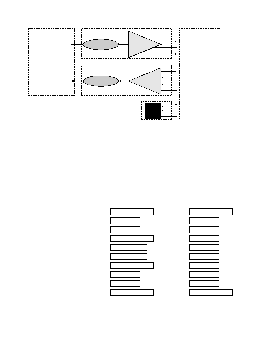
Figure 1. HFBR-5701L block diagram.
Overview
The HFBR-5701L offers maxi-
mum flexibility to designers,
manufacturers, and operators of
Gigabit Ethernet networking
equipment. A pluggable architec-
ture allows the module to be
installed into MSA standard SFP
ports at any time ≠ even with the
host equipment operating and
online. This facilitates the rapid
configuration of equipment to
precisely the user's needs ≠
reducing inventory costs and
network downtime. Compared
with traditional transceivers, the
size of the Small Form Factor
package enables higher port
densities.
Module Diagrams
Figure 1 illustrates the major
functional components of the
HFBR-5701L. The external
configuration of the module is
depicted in Figure 7. Figure 8
depicts the panel and host board
footprints.
Installation
The HFBR-5701L can be installed
in or removed from any MSA-
compliant Pluggable Small Form
Figure 2. Pin description of the SFP electrical interface.
Factor port regardless of whether
the host equipment is operating
or not. The module is simply
inserted, electrical-interface first,
under finger-pressure. Controlled
hot-plugging is ensured by
3-stage pin sequencing at the
electrical interface. This printed
circuit board card-edge connector
is depicted in Figure 2.
As the HFBR-5701L is inserted,
first contact is made by the
housing ground shield,
discharging any potentially
component-damaging static
electricity. Ground pins engage
next and are followed by Tx and
Rx power supplies. Finally, signal
lines are connected. Pin functions
and sequencing are listed in
Table 2.
VEET
20
TD≠
19
TD+
18
VEET
17
VCCT
16
VCCR
15
VEER
14
RD+
13
RD≠
12
VEER
11
TOP OF BOARD
VEET
1
TX FAULT
2
TX DISABLE
3
MOD-DEF(2)
4
MOD-DEF(1)
5
MOD-DEF(0)
6
RATE SELECT
7
LOS
8
VEER
9
VEER
10
BOTTOM OF BOARD
(AS VIEWED THROUGH TOP OF BOARD)
ENGAGEMENT
SEQUENCE
3 2 1
3 2 1
INCOMING OPTICAL SIGNAL
OUTGOING OPTICAL SIGNAL
PHOTODETECTOR
RECEIVER
AMPLIFICATION
& QUANTIZATION
RD+ (RECEIVE DATA)
RD≠ (RECEIVE DATA)
LOSS OF SIGNAL
VCSEL
TRANSMITTER
LASER
DRIVER &
SAFETY
CIRCUITRY
TX_DISABLE
TD+ (TRANSMIT DATA)
TD≠ (TRANSMIT DATA)
TX_FAULT
ELECTRICAL INTERFACE
MOD-DEF2
MOD-DEF1
MOD-DEF0
EEPROM
OPTICAL INTERFACE
3
Before extracting the module, the
black plastic tab beneath the
optical port must be depressed,
releasing the latch mechanism.
The transceiver can then be
pulled out of the port manually by
gripping the side of the LC ports.
For easier fingertip delatching in
high port density applications, an
optional extended tab is offered
as shown in Figure 10.
Serial Identification (EEPROM)
The HFBR-5701L features an
EEPROM for Serial ID. It
contains the product data stored
for retrieval by host equipment.
This data is accessed via the 2-
wire serial EEPROM protocol of
the ATMEL AT24C01A or similar
in compliance with the industry
standard SFP Multi-Source
Agreement. Contents of the
HFBR-5701L serial ID memory
are displayed in Table 9.
Transmitter Section
The transmitter section includes
the Transmitter Optical Sub-
assembly (TOSA) and laser driver
circuitry. The TOSA, containing
an 850 nm VCSEL (Vertical
Cavity Surface Emitting Laser)
light source, is located at the
optical interface and mates with
the LC optical connector. The
TOSA is driven by a custom IC,
which converts differential logic
signals into an analog laser diode
drive current. This Tx driver
circuit regulates the optical
power at a constant level
provided the data pattern is DC
balanced (8B10B code for
example).
Tx Disable
The HFBR-5701L accepts a
transmit disable control signal
input which shuts down the
transmitter. A high signal
implements this function while a
low signal allows normal laser
operation. In the event of a fault
(e.g., eye safety circuit activated),
cycling this control signal resets
the module as depicted in Figure 6.
Eye Safety Circuit
The HFBR-5701L provides Class
1 eye safety by design and has
been tested for compliance with
the requirements listed in
Table 1. The eye safety circuit
continuously monitors optical
output power levels and will
disable the transmitter and assert
a TX_FAULT signal upon
detecting an unsafe condition.
Such unsafe conditions can be
created by inputs from the host
board (Vcc fluxuation,
unbalanced code) or faults within
the module.
Receiver Section
The receiver section includes the
Receiver Optical Subassembly
(ROSA) and amplification/
quantization circuitry. The ROSA,
containing a PIN photodiode and
custom trans-impedance
preamplifier, is located at the
optical interface and mates with
the LC optical connector. The
ROSA is mated to a custom IC
that provides post-amplification
and quantization. Also included is
a Loss Of Signal (LOS) detection
circuit.
Loss of Signal
The Loss Of Signal (LOS) output
indicates an unusable optical
input power level. A high LOS
output signal indicates a loss of
signal while a low LOS output
signal indicates normal operation.
The Loss Of Signal thresholds are
set to indicate a definite optical
fault has occurred (e.g.,
disconnected or broken fiber
connection to receiver, failed
transmitter, etc.).
Functional I/O
The HFBR-5701L accepts
industry standard differential
signals such as LVPECL and CML
within the scope of the SFP MSA.
To simplify board requirements,
transmitter bias resistors and
coupling capacitors are
incorporated into the transceiver
module. The module is "ac-
coupled" and internally
terminated.
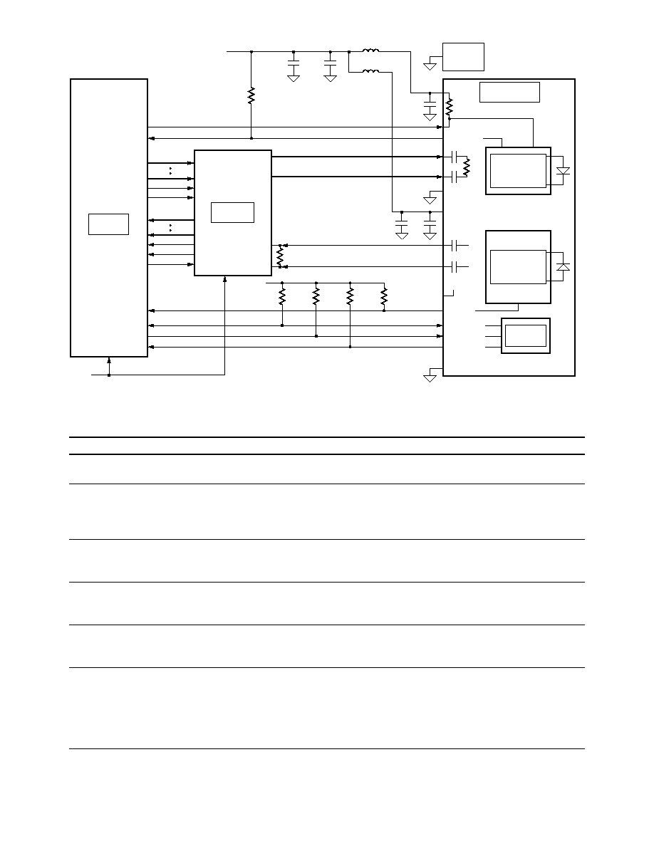
Figure 4 illustrates a recom-
mended interface circuit to link
the HFBR-5701L to the
supporting Physical Layer
integrated circuits.
Timing diagrams for the MSA
compliant control signals
implemented in this module are
depicted in Figure 6.
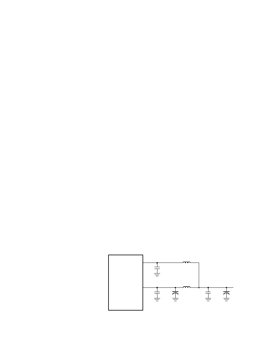
Figure 3. MSA required power supply filter.
1 µH
1 µH
0.1 µF
VCCR
SFP MODULE
10 µF
VCCT
0.1 µF
10 µF
3.3 V
HOST BOARD
0.1 µF

4
Required Host Board Components
The MSA power supply noise
rejection filter is required on the
host PCB to meet data sheet
performance. The MSA filter
incorporates an inductor which
should be rated 400 mADC and
1
series resistance or better. It
should not be replaced with a
ferrite. The required filter is
illustrated in Figure 3.
The MSA also specifies that 4.7 K
to 10 K
pull-up resistors for
TX_FAULT, LOS, and
MOD_DEF0,1,2 are required on
the host PCB.
Application Support
Evaluation Kit
To assist in the transceiver
evaluation process, Agilent offers
a 1.25 Gbd Gigabit Ethernet
evaluation board which facilitates
testing of the HFBR-5701L. It can
be obtained through the Agilent
Field Organization by referencing
Agilent part number HFBR-0571.
Reference Designs
A Reference Design including the
HFBR-5701L and the HDMP-
1687 GigaBit Quad SerDes is
available. It may be obtained
through the Agilent Field Sales
organization.
Regulatory Compliance
See Table 1 for transceiver
Regulatory Compliance. Certi-
fication level is dependent on the
overall configuration of the host
equipment. The transceiver
performance is offered as a figure
of merit to assist the designer.
Electrostatic Discharge (ESD)
There are two design cases in
which immunity to ESD damage
is important.
The first case is during handling
of the transceiver prior to
insertion into the transceiver
port. To protect the transceiver,
it's important to use normal ESD
handling precautions. These
precautions include using
grounded wrist straps, work
benches, and floor mats in ESD
controlled areas. The ESD
sensitivity of the HFBR-5701L is
compatible with typical industry
production environments.
The second case to consider is
static discharges to the exterior
of the host equipment chassis
after installation. To the extent
that the optical interface is
exposed to the outside of the host
equipment chassis, it may be
subject to system-level ESD
requirements.
Immunity
The ESD performance of the
HFBR-5701L exceeds typical
industry standards.
Equipment hosting HFBR-5701L
modules will be subjected to
radio-frequency electromagnetic
fields in some environments. The
transceiver has good immunity to
such fields due to its shielded
design.
Electromagnetic Interference (EMI)
Equipment incorporating Gigabit
Ethernet transceivers is typically
required to meet the require-
ments of the FCC in the United
States, CENELEC EN55022
(CISPR 22) in Europe, and VCCI
in Japan.
The metal housing and shielded
design of the HFBR-5701L
minimize the EMI challenge
facing the host equipment
designer.
Flammability
The HFBR-5701L transceiver is
made of metal and high strength,
heat resistant, chemically
resistant, and UL 94V-0 flame
retardant plastic.
Caution
There are no user serviceable
parts nor any maintenance
required for the HFBR-5701L. All
adjustments are made at the
factory before shipment to our
customers. Tampering with,
modifying, misusing or improp-
erly handling the HFBR-5701L
will void the product warranty. It
may also result in improper
operation of the HFBR-5701L
circuitry, and possible overstress
of the laser source. Device
degradation or Product failure
may result. Connection of the
HFBR-5701L to a non-Gigabit
Ethernet-compliant optical
source, operating above the
recommended absolute maximum
conditions or operating the
HFBR-5701L in a manner
inconsistent with its design and
function may result in hazardous
radiation exposure and may be
considered an act of modifying or
manufacturing a laser product.
The person(s) performing such
an act is required by law to re-
certify and re-identify the laser
product under the provisions of
U.S. 21 CFR (Subchapter J).
5
Table 1. Regulatory Compliance
Feature
Test Method
Performance
Electrostatic Discharge (ESD)
JEDEC/EIA
Class 2 (> +2000 Volts)
to the Electrical Pins
JESD22-A114-A
Electrostatic Discharge (ESD)
Variation of IEC 6100-4-2
Typically withstands at least 25 kV without
to the Duplex LC Receptacle
damage when the duplex LC connector
receptacle is contacted by a Human Body
Model probe
Electromagnetic Interference
FCC Class B
Applications with high SFP port counts are
(EMI)
CENELEC EN55022 Class B
expected to be compliant; however, margins are
(CISPR 22A) VCCI Class 1
dependent on customer board and chassis design.
Immunity
Variation of IEC 61000-4-3
Typically shows a negligible effect from a
10 V/m field swept from 80 to 1000 MHz applied
to the transceiver without a chassis enclosure.
Eye Safety
[1]
US FDA CDRH AEL Class 1
CDRH certification #9720151-13
EN(IEC)60825-1,2, EN60950
TUV file #E9971083.07
Class 1
Component Recognition
Underwriters Laboratories and
UL File #E173874
Canadian Standards Associa-
tion Joint Component Recognition
for Information Technology
Equipment Including Electrical
Business Equipment
Note:
1. Changes to IEC 60825-1,2 are currently anticipated to allow higher eye-safe Optical Output Power levels. Agilent may choose to take advantage of these
in future revisions to this part.
Figure 4. Typical application configuration.
LASER DRIVER
& EYE SAFETY
CIRCUITRY
50
50
SO1+
SO1≠
AMPLIFICATION
&
QUANTIZATION
50
50
SI1+
SI1≠
VREFR
TBC
EWRAP
RBC
RX_RATE
RX_LOS
GPIO(X)
GPIO(X)
GP14
TX_FAULT
GP04
SYNC
LOOP
SYN1
RC1(0:1)
RFCT
TX[0:9]
RX[0:9]
TX_FAULT
TX_DISABLE
VEET
RD+
RD≠
RX_LOS
MOD_DEF2
EEPROM
MOD_DEF1
MOD_DEF0
REF_RATE
NOTE: * 4.7 k < RES < 10 k
V
CC
T,R
125 MHz
AGILENT
HFBR-5701L
V
CC
T
1 µH
1 µH
10 µF
0.1 µF
V
CC
T,R
V
CC
R
10
µF
0.1
µF
0.1
µF
AGILENT
HDMP-1687
R
RCM0
C
C
REFCLK
MAC
ASIC
*RES
*RES
*RES
*RES
VEER
TD+
TD≠
C
C
R
*RES
HOUSING
GROUND
*RES