Äîêóìåíòàöèÿ è îïèñàíèÿ www.docs.chipfind.ru
Agilent HFBR-5720L/5720LP
Fibre Channel 2.125/1.0625 GBd 850 nm
Small Form Pluggable Low Voltage (3.3 V)
Optical Transceiver
Data Sheet
Features
· Compliant with 2.125 GBd Fibre
Channel FC-PI standard
· FC-PI 200-M5-SN-I for 50/125
µ
m
multimode cables
· FC-PI 200-M6-SN-I for 62.5/125
µ
m
multimode cables
· Compliant with 1.0625 GBd VCSEL
operation for both 50/125 and 62.5/125
µ
m
multimode cables
· Industry standard Small Form Pluggable
(SFP) package
· LC-Duplex connector optical interface
· Link lengths at 2.125 GBd:
0.5 to 300 m 50/125
µ
m MMF
0.5 to 150 m 62.5/125
µ
m MMF
· Link lengths at 1.0625 GBd:
0.5 to 500 m 50/125
µ
m MMF
0.5 to 300 m 62.5/125
µ
m MMF
· Reliable 850 nm Vertical Cavity Surface
Emitting Laser (VCSEL) source
technology
· Laser AEL Class 1 (eye safe) per:
US 21 CFR (J)
EN-60825-1 (+A11+A2)
· Single 3.3 V power supply operation
· De-latch options:
HFBR-5720L standard de-latch
HFBR-5720LP extended de-latch
Applications
· Mass storage system I/O
· Computer system I/O
· High speed peripheral interface
· High speed switching systems
· Host adapter I/O
· RAID cabinets
Related Products
· HFBR-5602: 850 nm 5 V Gigabit Interface
Converter (GBIC) for Fibre Channel FC-PH-2
· HFBR-53D3: 850 nm 5 V 1 x 9 laser trans-
ceiver for Fibre Channel FC-PH-2
· HFBR-5910E: 850 nm 3.3 V SFF laser trans-
ceiver for Fibre Channel FC-PH-2
· HDMP-2630/2631: 2.125/1.0625 Gbps TRx
family of SerDes IC
Description
The HFBR-5720L optical
transceiver from Agilent
Technologies offers maximum
flexibility to Fibre Channel
designers, manufacturers, and
system integrators to implement a
range of solutions for multimode
Fibre Channel applications. In order
to provide a wide range of system
level performance, without the need
for a data rate select input, this
product is fully compliant with all
equipment meeting the Fibre
Channel FC-PI 200-M5-SN-I and
200-M6-SN-I 2.125 GBd
specifications, and is compatible
with the Fibre Channel FC-PI 100-
M5-SN-I and FC-PI 100-M6-SN-I,
FC-PH2 100-M5-SN-I, and the FC-
PH2 100-M6-SN-I 1.0625 GBd
specifications.
Module Package
The transceiver meets the Small
Form Pluggable (SFP) industry
standard package utilizing an
integral LC-Duplex optical interface
connector. The hot-pluggable
capability of the SFP package
allows the module to be installed
at any time even with the host
system operating and on-line.
This allows for system
configuration changes or
maintenance without system
down time. The HFBR-5720L
uses a reliable 850 nm VCSEL
source and requires a 3.3 V DC
power supply for optimal design.
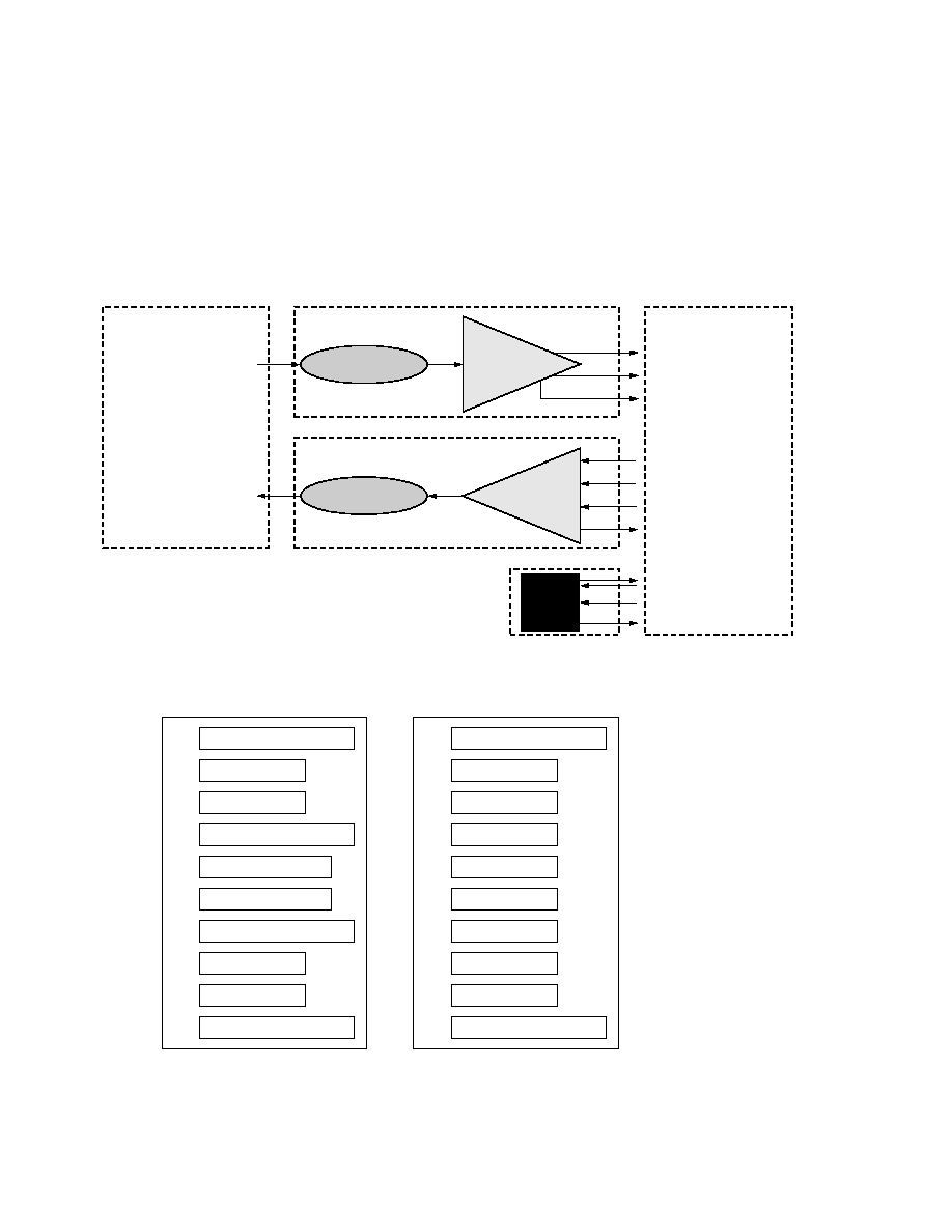
Module Diagrams
Figure 1 illustrates the major
functional components of the
HFBR-5720L. The connection
diagram of the module is shown
in Figure 2. Figure 7 depicts the
external configuration and
dimensions of the module.
Installation
The HFBR-5720L can be installed
in or removed from any
MultiSource Agreement (MSA)-
compliant Small Form Pluggable
port regardless of whether the
host equipment is operating or
not. The module is simply
inserted, electrical interface first,
under finger pressure. Controlled
2
Figure 2. Connection diagram of module printed circuit board.
VEET
20
TD
19
TD+
18
VEET
17
VCCT
16
VCCR
15
VEER
14
RD+
13
RD
12
VEER
11
TOP OF BOARD
VEET
1
TxFAULT
2
Tx DISABLE
3
MOD-DEF(2)
4
MOD-DEF(1)
5
MOD-DEF(0)
6
RATE SELECT
7
LOS
8
VEER
9
VEER
10
BOTTOM OF BOARD
(AS VIEWED THROUGH TOP OF BOARD)
hot-plugging is ensured by design
and by 3-stage pin sequencing at
the electrical interface. The
module housing makes initial
contact with the host board EMI
shield mitigating potential
damage due to Electro-Static
Discharge (ESD). The 3-stage pin
contact sequencing involves (1)
Ground, (2) Power, and then (3)
Signal pins, making contact with
the host board surface mount
connector in that order. This
printed circuit board card-edge
connector is depicted in Figure 2.
Serial Identification (EEPROM)
The HFBR-5720L complies with
an industry standard MSA that
defines the serial identification
protocol. This protocol uses the
2-wire serial CMOS E2PROM
protocol of the ATMEL
AT24C01A or equivalent. The
Figure 1. Transceiver functional diagram.
LIGHT FROM FIBER
OPTICAL INTERFACE
LIGHT TO FIBER
PHOTO-DETECTOR
RECEIVER
AMPLIFICATION
& QUANTIZATION
RD+ (RECEIVE DATA)
RD (RECEIVE DATA)
LOSS OF SIGNAL
VCSEL
TRANSMITTER
LASER
DRIVER &
SAFETY
CIRCUITRY
Tx_DISABLE
TD+ (TRANSMIT DATA)
TD (TRANSMIT DATA)
Tx_FAULT
ELECTRICAL INTERFACE
MOD-DEF2
MOD-DEF1
MOD-DEF0
EEPROM
HFBR-5720L BLOCK DIAGRAM
3
contents of the HFBR-5720L
serial ID memory are defined in
Table 10 as specified in the SFP
MSA.
Transmitter Section
The transmitter section includes
the transmitter optical
subassembly (TOSA) and laser
driver circuitry. The TOSA,
containing an 850 nm VCSEL
(Vertical Cavity Surface Emitting
Laser) light source, is located at
the optical interface and mates
with the LC optical connector.
The TOSA is driven by a custom
silicon IC, which converts
differential logic signals into an
analog laser diode drive current.
This Tx driver circuit regulates
the optical power at a constant
level provided the data pattern is
valid 8B/10B balanced code.
Tx Disable
The HFBR-5720L accepts a
transmit disable control signal
input which shuts down the
transmitter. A high signal
implements this function while a
low signal allows normal laser
operation. In the event of a fault
(e.g., eye safety circuit activated),
cycling this control signal resets
the module as depicted in
Figure 6. The Tx Disable control
should be actuated upon
initialization of the module.
Tx Fault
The HFBR-5720L module
features a transmit fault control
signal output which when high
indicates a laser transmit fault
has occurred and when low
indicates normal laser operation.
A transmitter fault condition can
be caused by deviations from the
recommended module operating
conditions or by violation of eye
safety conditions. A fault is
cleared by cycling the Tx Disable
control input.
Eye Safety Circuit
For an optical transmitter device
to be eye-safe in the event of a
single fault failure, the
transmitter will either maintain
normal eye-safe operation or be
disabled. In the event of an eye
safety fault, the VCSEL will be
disabled.
Receiver Section
The receiver section includes the
receiver optical subassembly
(ROSA) and amplification/
quantization circuitry. The ROSA,
containing a PIN photodiode and
custom transimpedance
preamplifier, is located at the
optical interface and mates with
the LC optical connector. The
ROSA is mated to a custom IC
that provides post-amplification
and quantization. This circuit also
includes a loss of signal (LOS)
detection circuit which provides
an open collector logic high
output in the absence of a usable
input optical signal level.
Loss of Signal
The Loss of Signal (LOS) output
indicates that the optical input
signal to the receiver does not
meet the minimum detectable
level for Fibre Channel compliant
signals. When LOS is high it
indicates loss of signal. When
LOS is low it indicates normal
operation. The Loss of Signal
thresholds are set to indicate a
definite optical fault has occurred
(e.g., disconnected or broken
fiber connection to receiver,
failed transmitter).
Functional Data I/O
Agilent's HFBR-5720L fiber-optic
transceiver is designed to accept
industry standard differential
signals. In order to reduce the
number of passive components
required on the customer's board,
Agilent has included the
functionality of the transmitter
bias resistors and coupling
capacitors within the fiber optic
module. The transceiver is
compatible with an "AC-coupled"
configuration and is internally
terminated. Figure 1 depicts the
functional diagram of the HFBR-
5720L.
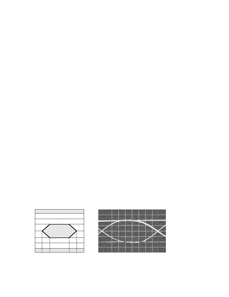
Figure 3. Transmitter eye mask diagram and typical transmitter eye.
0.8
0.5
0.2
0
x1
0.4
1-x1
NORMALIZED TIME
NORMALIZED AMPLITUDE
1.0
1.0
0
1.3
0.6
0.2

4
Caution should be taken for the
proper interconnection between
the supporting Physical Layer
integrated circuits and the HFBR-
5720L. Figure 4 illustrates the
recommended interface circuit.
Several MSA compliant control
data signals are implemented in
the module and are depicted in
Figure 6.
Application Support
Evaluation Kit
To help you in your preliminary
transceiver evaluation, Agilent
offers a 2.125 GBd Fibre Channel
evaluation board. This board will
allow testing of the fiber-optic
VCSEL transceiver. Please
contact your local field sales
representative for availability and
ordering details.
Reference Designs
Reference designs for the HFBR-
5720L fiber-optic transceiver and
the HDMP-2630/2631 physical
layer IC are available to assist the
equipment designer. Figure 4
depicts a typical application
configuration, while Figure 5
depicts the MSA power supply
filter circuit design. All artwork is
available at the Agilent Website.
Please contact your local field
sales engineer for more
information regarding application
tools.
Regulatory Compliance
See Table 1 for transceiver
Regulatory Compliance
performance. The overall
equipment design will determine
the certification level. The
transceiver performance is
offered as a figure of merit to
assist the designer.
Electrostatic Discharge (ESD)
There are two conditions in which
immunity to ESD damage is
important. Table 1 documents our
immunity to both of these
conditions. The first condition is
during handling of the transceiver
prior to insertion into the
transceiver port. To protect the
transceiver, it is important to use
normal ESD handling
precautions. These precautions
include using grounded wrist
straps, work benches, and floor
mats in ESD controlled areas.
The ESD sensitivity of the HFBR-
5720L is compatible with typical
industry production
environments. The second
condition is static discharges to
the exterior of the host
equipment chassis after
installation. To the extent that the
duplex LC optical interface is
exposed to the outside of the host
equipment chassis, it may be
subject to system-level ESD
requirements. The ESD
performance of the HFBR-5720L
exceeds typical industry
standards.
Immunity
Equipment hosting the HFBR-
5720L modules will be subjected
to radio-frequency electro-
magnetic fields in some
environments. These transceivers
have good immunity to such
fields due to their shielded
design.
Electromagnetic Interference (EMI)
Most equipment designs utilizing
these high-speed transceivers
from Agilent Technologies will be
required to meet the
requirements of FCC in the
United States, CENELEC
EN55022 (CISPR 22) in Europe
and VCCI in Japan.
The metal housing and shielded
design of the HFBR-5720L
minimize the EMI challenge
facing the host equipment
designer. These transceivers
provide superior EMI
performance. This greatly assists
the designer in the management
of the overall system EMI
perfornmance.
Eye Safety
These 850 nm VCSEL-based
transceivers provide Class 1 eye
safety by design. Agilent
Technologies has tested the
transceiver design for compliance
with the requirements listed in
Table 1 under normal operating
conditions and under a single
fault condition.
Flammability
The HFBR-5720L VCSEL
transceiver housing is made of
metal and high strength, heat
resistant, chemically resistant,
and UL 94V-0 flame retardant
plastic.
Caution
There are no user serviceable
parts nor any maintenance
required for the HFBR-5720L.
Tampering with or modifying the
performance of the HFBR-5720L
will result in voided product
warranty. It may also result in
improper operation of the HFBR-
5720L circuitry, and possible
overstress of the laser source.
Device degradation or product
failure may result. Connection of
the HFBR-5720L to a non-
approved optical source,
operating above the recommend-
ed absolute maximum conditions
or operating the HFBR-5720L in
a manner inconsistent with its
design and function may result in
hazardous radiation exposure and
may be considered an act of
modifying or manufacturing a
laser product. The person(s)
performing such an act is
required by law to re-certify and
re-identify the laser product
under the provisions of U.S. 21
CFR (Subchapter J) and the TUV.
Ordering Information
Please contact your local field
sales engineer or one of the

5
Agilent Technologies franchised
distributors for ordering
information. For additional
technical information associated
with this product, including the
MSA, please visit Agilent
Technologies Semiconductor
Products Website at
www.agilent.com/view/fiber
Use the Quick Search feature to
search for this part number.
Agilent Technologies
Semiconductor Products
Customer Response Center is
also available to assist you at
1-800-235-0312.
Table 1. Regulatory Compliance
Feature
Test Method
Performance
Electrostatic Discharge (ESD)
MIL-STD-883C Method 3015.4
Class 2 (>2000 Volts)
to the Electrical Pins
Electrostatic Discharge (ESD)
Variation of IEC 61000-4-2
Typically withstand at least 25 kV without
to the Duplex LC Receptacle
damage when the duplex LC connector
receptacle is contacted by a Human Body
Model probe.
Electromagnetic Interference
FCC Class B
System margins are dependent on customer
(EMI)
CENELEC EN55022 Class B
board and chassis design.
(CISPR 22A)
VCCI Class 1
Immunity
Variation of IEC 61000-4-3
Typically shows a negligible effect from a
10 V/m field swept from 80 to 1000 MHz
applied to the transceiver without a chassis
enclosure.
Eye Safety
US FDA CDRH AEL Class 1
CDRH File # 9720151-16 (HFBR-5720L)
CDRH File # Pending
(HFBR-5720LP)
EN 60950 Class 1
EN (IEC) 60825-1:1994+A11+A2
TUV File # E2171216.01 (HFBR-5720L)
Note 1
EN (IEC) 60825-2:1994+A1
TUV File # Pending
(HFBR-5720LP)
Component Recognition
Underwriters Laboratories and
UL file # E173874
Canadian Standards Association
Joint Component Recognition for
Information Technology Equipment
Including Electrical Business Equipment
Note:
1. Units manufactured prior to August 1, 2001 were certified to the previous TUV standard EN60825-1:1994+A11.
Document Outline