Plastic Optical Fiber
Cable and Accessories for
Versatile Link
Technical Data
Features
∑ Compatible with Agilent
Versatile Link Family of
Connectors and Fiber Optic
Components
∑ 1 mm Diameter Plastic
Optical Fiber (POF) in Two
Grades: Low Cost Standard
POF with 0.22 dB/m Typical
Attenuation, or High
Performance Extra Low Loss
POF with 0.19 dB/m Typical
Attenuation
Applications
∑ Industrial Data Links for
Factory Automation and
Plant Control
∑ Intra-System Links; Board-
to-Board, Rack-to-Rack
∑ Telecommunications
Switching Systems
∑ Computer-to-Peripheral Data
Links, PC Bus Extension
∑ Proprietary LANs
∑ Digitized Video
∑ Medical Instruments
∑ Reduction of Lightning and
Voltage Transient
Susceptibility
∑ High Voltage Isolation
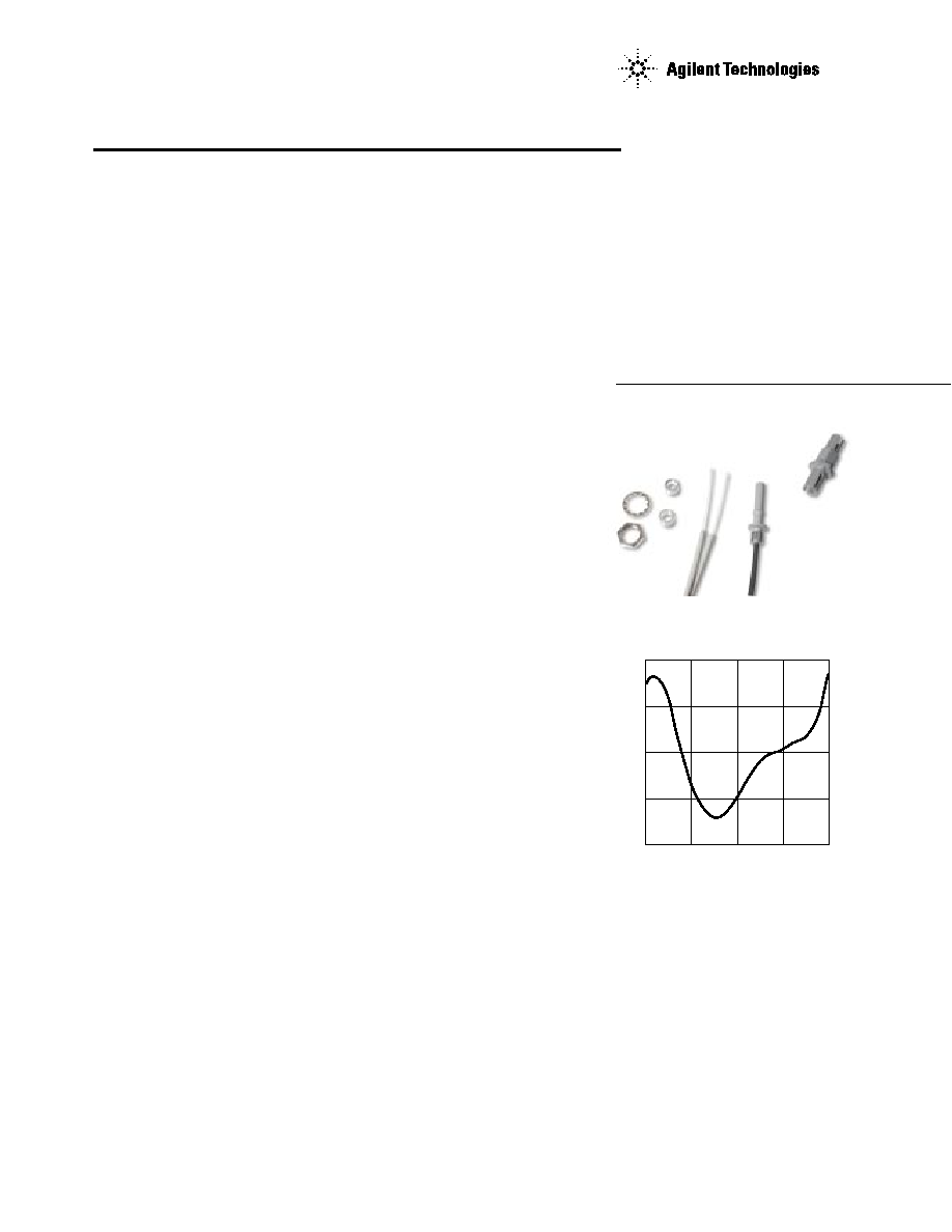
Cable Description
The HFBR-R/EXXYYY series of
plastic fiber optic cables are
constructed of a single step-index
fiber sheathed in a black poly-
ethylene jacket. The duplex fiber
consists of two simplex fibers
joined with a zipcord web.
Standard attenuation and extra
low loss POF cables are identical
except for attenuation
specifications.
Polyethylene jackets on all plastic
fiber cables comply with UL VW-1
flame retardant specification (UL
file # E89328).
Cables are available in
unconnectored or connectored
options. Refer to the Ordering
Guide for part number
information.
HFBR-RXXYYY Series (POF)
HFBR-EXXYYY Series (POF)
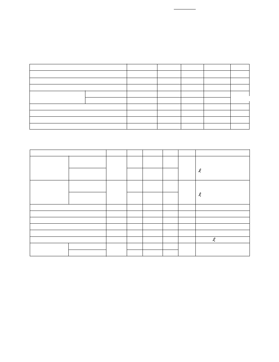
Figure 1. Typical POF Attenuation vs.
Wavelength.
R
≠ ATTENUATION ≠ dB/km
620
500
100
≠ WAVELENGTH ≠ nm
660
300
400
680
640
700
200
2
Plastic Optical Fiber Specifications: HFBR-R/EXXYYY
Absolute Maximum Ratings
Parameter
Symbol
Min.
Max.
Unit
Note
Storage and Operating Temperature
T
S,O
-55
+85
∞
C
Recommended Operating Temperature
T
O
-40
+85
∞
C
Installation Temperature
T
I
-20
+70
∞
C
1
Short Term Tensile
Single Channel
F
T
50
N
2
Dual Channel
F
T
100
N
Short Term Bend Radius
r
25
mm
3, 4
Long Term Bend Radius
r
35
mm
Long Term Tensile Load
F
T
1
N
Flexing
1000
Cycles
4
Mechanical/Optical Characteristics, T
A
= -40 to +85
∞
C unless otherwise specified.
Parameter
Symbol
Min.
Typ.
[5]
Max.
Unit
Condition
Cable
Standard Cable,
O
0.15
0.22
0.27
dB/m
Source is HFBR-15XX
Attenuation
Type "R"
(660 mm LED, 0.5 NA)
Extra Low Loss,
0.15
0.19
0.23
= 50 meters
Type "E"
Reference
Standard Cable,
R
0.12
0.19
0.24
dB/m
Source is 650 nm,
Attenuation
Type "R"
0.5 NA monochrometer,
Extra Low Loss,
0.12
0.16
0.19
= 50 meters
Type "E"
Note 7, Figure 1
Numerical Aperture
NA
0.46
0.47
0.50
>2 meters
Diameter, Core and Cladding
D
C
0.94
1.00
1.06
mm
Diameter, Jacket
D
J
2.13
2.20
2.27
mm
Simplex Cable
Propagation Delay Constant
l/v
5.0
ns/m
Note 6
Mass per Unit Length/Channel
5.3
g/m
Without Connectors
Cable Leakage Current
I
L
12
nA
50 kV,
= 0.3 meters
Refractive Index
Core
n
1.492
Cladding
1.417
Notes:
1. Installation temperature is the range over which the cable can be bent and pulled
without damage. Below -20
∞
C the cable becomes brittle and should not be subjected to
mechanical stress.
2. Short Term Tensile Force is for less than 30 minutes.
3. Short Term Bend Radius is for less than 1 hour nonoperating.
4. 90
∞
bend on 25 mm radius mandrel. Bend radius is the radius of the mandrel around
which the cable is bent.
5. Typical data are at 25
∞
C.
6. Propagation delay constant is the reciprocal of the group velocity for propagation delay
of optical power. Group velocity is v=c/n where c is the velocity of light in free space
(3xl0
8
m/s) and n is the effective core index of refraction.
7. Note that
R
rises at the rate of about 0.0067 dB/
∞
C, where the thermal rise refers to
the LED temperature changes above 25
∞
C. Please refer to Figure 1 which shows the
typical plastic optical fiber attenuation versus wavelength at 25
∞
C.
Force
3
HFBR-4503/4513 -- Simplex Latching
The simplex latching connector is
designed for rugged applications
requiring a greater retention force
-- 80 Newtons ( 18 lb.) -- than
provided by a simplex nonlatching
connector. When inserting the
simplex latching connector into a
module, the connector latch
mechanism should be aligned
with the top surface of the
horizontal modules, or with the
tall vertical side of the vertical
modules. Misalignment of an
inserted latching connector into
either module will not result in a
positive latch. The connector is
released by depressing the rear
section of the connector lever,
and then pulling the connector
assembly away from the module
housing.
The simplex latching connector is
available in gray (HFBR-4503) or
blue (HFBR-4513).
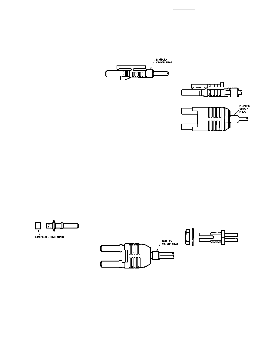
DUPLEX CONNECTOR STYLES
HFBR-4506 -- Duplex
Duplex connectors provide con-
venient duplex cable termination
and are keyed to prevent incorrect
insertion into duplex configured
modules. The duplex connector is
compatible with dual combina-
tions of horizontal or vertical
Versatile Link components (e.g.,
two horizontal transmitters, two
vertical receivers, a horizontal
transmitter with a horizontal
receiver, etc.). The duplex non-
HFBR-4526
Plastic Fiber Connector
Styles
Connector Description
Four connector styles are available
for termination of plastic optical
fiber: simplex, simplex latching,
duplex and duplex latching. All
connectors provide a snap-in
action when mated to Versatile
Link components. Simplex
connectors are color coded to
facilitate identification of trans-
mitter and receiver connections.
Duplex connectors are keyed so
that proper orientation is ensured
during insertion. If the POF cable/
connector will be used at extreme
operating temperatures or
experience frequent and wide
temperature cycling effects, the
cable/connector attachment can
be strengthened with an RTV
adhesive (see Plastic Connector-
ing Instructions for more detail).
The connectors are made of a
flame retardant VALOX UL94 V-0
material (UL file # E121562).
SIMPLEX CONNECTOR STYLES
HFBR-4501/4511 -- Simplex
The simplex connector provides a
quick and stable connection for
applications that require a
component-to-connector retention
force of 8 Newtons (1.8 lb.).
These connectors are available in
gray (HFBR-4501) or blue
(HFBR-4511).
latching connector is available in
parchment, off-white (HFBR-
4506).
HFBR-4516 -- Duplex Latching
The duplex latching connector is
designed for rugged applications
requiring greater retention force
than the nonlatching duplex con-
nector. When inserting the duplex
latching connector into a module,
the connector latch mechanism
should be aligned with the top
surface of the dual combination of
horizontal or vertical Versatile
Link components. The duplex
latching connector is available in
gray (HFBR-4516).
Feedthrough/Splice
HFBR-4505/4515 Bulkhead Adapter
The HFBR-4505/4515 adapter
mates two simplex connectors for
panel/bulkhead feedthrough of
HFBR-4501/4511 terminated
plastic fiber cable. Maximum
panel thickness is 4.1 mm (0.16
inch). This adapter can serve as a
cable in-line splice using two
simplex connectors. The adapters
are available in gray (HFBR-
4505) and blue (HFBR-4515).
This adapter is not compatible
with POF duplex, POF simplex
latching, or HCS connectors.
,
HFBR-4526
, HFBR-4525
HFBR-4525
4
Plastic Optical Fiber Connector Absolute Maximum Ratings
Parameter
Symbol
Min.
Max.
Unit
Note
Storage and Operating Temperature
T
S,O
-40
85
∞
C
1
Recommended Operating Temperature
T
O
-40
85
∞
C
1
Installation Temperature
T
l
0
70
∞
C
1
Nut Torque
T
N
0.7
N-m
2
100
OzF-in.
Notes:
1. Storage and Operating Temperatures refer to the ranges over which the connectors can be used when not subjected to mechanical
stress. Installation Temperature refers to the ranges over which connectors may be installed onto the fiber and over which connectors
can be connected and disconnected from transmitter and receiver modules.
2. Recommended nut torque is 0.57 N-m.
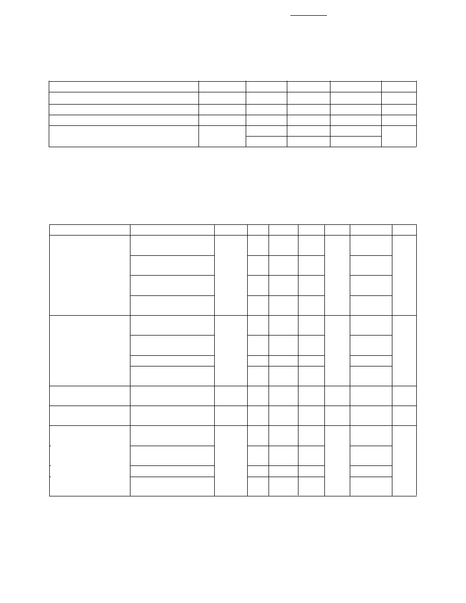
Plastic Optical Fiber Connector Mechanical/Optical Characteristics
T
A
= -40 to +85
∞
C, Unless Otherwise Specified.
Parameter
Part Number
Symbol Min. Typ.
[1]
Max. Units
Temp.
∞
C Note
Retention Force,
Simplex,
F
R-C
7
8
N
+25
2
Connector to
HFBR-4501/4511
3
-40 to +85
Simplex Latching,
47
80
+25
HFBR-4503/4513
11
-40 to +85
Duplex,
7
12
+25
HFBR-4506
4
-40 to +85
Duplex Latching,
50
80
+25
HFBR-4516
15
-40 to +85
Tensile Force,
Simplex,
F
T
8.5
22
N
3
Connector to Cable
HFBR-4501/4511
Simplex Latching,
8.5
22
HFBR-4503/4513
Duplex, HFBR-4506
14
35
Duplex Latching,
14
35
HFBR-4516
Adapter Connector
HFBR-4505/4515 with
CC
0.7
1.5
2.8
dB
25
4, 5
to Connector Loss
HFBR-4501/4511
Retention Force
HFBR-4505/4515 with
F
R-B
7
8
N
Connector to Adapter
HFBR-4501/4511
Insertion Force,
Simplex,
F
I
8
30
N
6
HFBR-4501/4511
Simplex Latching,
16
35
HFBR-4503/4513
Duplex, HFBR-4506
13
46
Duplex Latching
22
51
HFBR-4516
Notes:
1. Typical data are at +25
∞
C.
2. No perceivable reduction in retention force was observed after 2000 insertions. Retention force of non-latching connectors is lower at
elevated temperatures. Latching connectors are recommended for applications where a high retention force at high temperatures is
desired.
3. For applications where frequent temperature cycling over temperature extremes is expected, please contact Agilent Technologies for
alternate connectoring techniques.
4. Minimum and maximum limit for
CC
for 0
∞
C to +70
∞
C temperature range. Typical value of
CC
is at +25
∞
C.
5. Factory polish or field polish per recommended procedure.
6. Destructive insertion force was typically at 178 N (40 lb.).
HFBR-4505/4515 Adapter
Versatile Link
Transmitters and
Receivers
Connector to
Versatile Link
Transmitters and
Receivers

5
Step-by-Step Plastic
Cable Connectoring
Instructions
The following step-by-step guide
describes how to terminate plastic
fiber optic cable. It is ideal for
both field and factory installation.
Connectors can be easily installed
on cable ends with wire strippers,
cutters and a crimping tool.
Finishing the cable is accom-
plished with the Agilent
HFBR-4593 Polishing Kit, consist-
ing of a Polishing Fixture, 600
grit abrasive paper and 3
µ
m pink
lapping film (3M Company,
OC3-14). The connector can be
used immediately after polishing.
Materials needed for plastic fiber
termination are:
1. Agilent Plastic Optical Fiber
Cable (Example: HFBR-
RUS500, HFBR-RUD500,
HFBR-EUS500, or HFBR-
EUD500)
2. Industrial Razor Blade or Wire
Cutters
3. 16 Gauge Latching Wire
Strippers (Example: Ideal
Stripmaster
TM
type 45-092).
4. HFBR-4597 Crimping Tool
5. HFBR-4593 Polishing Kit
6. One of the following
connectors:
a) HFBR-4501/4503 Gray
Simplex/Simplex Latching
Connector and HFBR-4525
Simplex Crimp Ring
b) HFBR-4511/4513 Blue
Simplex/Simplex Latching
Connector and HFBR-4525
Simplex Crimp Ring
c) HFBR-4506 Parchment (off-
white) Duplex Connector
and HFBR-4526 Duplex
Crimp Ring
d) HFBR-4516 Gray Latching
Duplex Connector and
HFBR-4526 Duplex Crimp
Ring
Step 1
The zip cord structure of the
duplex cable permits easy
separation of the channels. The
channels should be separated a
minimum of 100 mm (4 in) to a
maximum of 150 mm (6 in) back
from the ends to permit
connectoring and polishing.
After cutting the cable to the
desired length, strip off approxi-
mately 7 mm (0.3 in.) of the outer
jacket with the 16 gauge wire
strippers. Excess webbing on the
duplex cable may have to be
trimmed to allow the simplex or
simplex latching connector to
slide over the cable.
When using the duplex connector
and duplex cable, the separated
duplex cable must be stripped to
equal lengths on each cable. This
allows easy and proper seating of
the cable into the duplex
connector.
Step 2
Place the crimp ring and connec-
tor over the end of the cable; the
fiber should protrude about 3 mm
(0.12 in.) through the end of the
connector. Carefully position the
ring so that it is entirely on the
connector with the rim of the
crimp ring flush with the connec-
tor, leaving a small space between
the crimp ring and the flange.
Then crimp the ring in place with
the crimping tool. One crimp tool
is used for all POF connector
crimping requirements.
For applications with extreme
temperature operation or frequent
temperature cycling, improved
connector to cable attachment
can be achieved with the use of an
RTV (GE Company, RTV-128 or
Dow Corning 3145-RTV)
adhesive. The RTV is placed into
the connector prior to insertion of
the fiber and the fiber is crimped
normally. The connector can be
polished after the RTV has cured
and is then ready for use.
Note: By convention, place the
gray connector on the trans-
mitter cable end and the blue
connector on the receiver cable
end to maintain color coding
(different color connectors are
mechanically identical).
Simplex connector crimp rings
cannot be used with duplex con-
nectors and duplex connector
crimp rings cannot be used
with simplex connectors because
of size differences. The simplex
crimp has a dull luster appear-
ance; the duplex ring is glossy
and has a thinner wall.