
Agilent HLMP-EDxx/EGxx/ELxx
5 mm Precision Optical Performance
Best Value AlInGaP Lamps
Data Sheet
Description
These Precision Optical Perform-
ance AlInGaP and AlInGaP II LEDs
provide superior light output for
excellent readability in sunlight and
are extremely reliable.
These LED lamps are untinted,
nondiffused, T-1 3/4 packages
incorporating second generation
optics producing well defined
spatial radiation patterns at specific
viewing cone angles.
Features
∑ Well defined spatial radiation
pattern
∑ Viewing angles:
6
∞
, 15
∞
, 23
∞
, 30
∞
∑ High luminous output
∑ Two red and amber intensity levels
AlInGaP (bright) and AlInGaP II
(brightest)
∑ Colors:
626/630 nm red
590/592 nm amber
∑ Superior resistance to moisture
∑ UV resistant epoxy
Benefits
∑ Viewing angles match traffic
management sign and
requirements
∑ Colors meet automotive and
pedestrian signal and
specifications
∑ Superior performance in outdoor
environments
∑ Suitable for autoinsertion onto PC
boards
Applications
∑ Traffic management:
Traffic signals
Work zone warning lights
Variable message signs
∑ Commercial outdoor advertising:
Signs
Marquees
∑ Automotive:
Exterior and Interior Lights
These lamps are made with an
advanced optical grade epoxy,
offering superior high
temperature and high moisture
resistance performance in outdoor
signal and sign applications. The
high maximum LED junction
temperature limit of +130
∞
C
enables high temperature
operation in bright sunlight
conditions. The package epoxy
contains both uv-a and uv-b
inhibitors to reduce the effects of
long term exposure to direct
sunlight.

3
Device Selection Guide for AlInGaP II
Color and
Luminous Intensity
Typical
Dominant
Iv (mcd)
[2][3]
Viewing Angle
Wavelength
at I
F
= 20 mA
Leads with
Package
Part Number
2
1/2
(nm), Typ.
[4]
Min.
Standoffs
Drawing
HLMP-ED16-S0000
15
∞
Red 630
1650
No
A
HLMP-ED16-S0T00
15
∞
Red 630
1650
No
A
HLMP-ED18-S0000
15
∞
Red 630
1650
Yes
B
HLMP-ED18-S0T00
15
∞
Red 630
1650
Yes
B
HLMP-ED25-R0000
23
∞
Red 630
1300
No
A
HLMP-ED25-R0T00
23
∞
Red 630
1300
No
A
HLMP-ED27-R0000
23
∞
Red 630
1300
Yes
B
HLMP-ED27-R0T00
23
∞
Red 630
1300
Yes
B
HLMP-ED31-Q0000
30
∞
Red 630
1000
No
A
HLMP-ED31-Q0T00
30
∞
Red 630
1000
No
A
HLMP-ED33-Q0000
30
∞
Red 630
1000
Yes
B
HLMP-ED33-Q0T00
30
∞
Red 630
1000
Yes
B
HLMP-EL16-S0000
15
∞
Amber 592
1650
No
A
HLMP-EL16-S0R00
15
∞
Amber 592
1650
No
A
HLMP-EL18-S0000
15
∞
Amber 592
1650
Yes
B
HLMP-EL18-S0R00
15
∞
Amber 592
1650
Yes
B
HLMP-EL25-Q0000
23
∞
Amber 592
1000
No
A
HLMP-EL25-Q0R00
23
∞
Amber 592
1000
No
A
HLMP-EL27-Q0000
23
∞
Amber 592
1000
Yes
B
HLMP-EL27-Q0R00
23
∞
Amber 592
1000
Yes
B
HLMP-EL31-P0000
30
∞
Amber 592
765
No
A
HLMP-EL31-P0R00
30
∞
Amber 592
765
No
A
HLMP-EL33-P0000
30
∞
Amber 592
765
Yes
B
HLMP-EL33-P0R00
30
∞
Amber 592
765
Yes
B
HLMP-EL31-Q0R00
30
∞
Amber 592
1000
No
A
Notes:
1. 2
1/2
is the off-axis angle where the luminous intensity is 1/2 the on-axis intensity.
2. The luminous intensity is measured on the mechanical axis of the lamp package.
3. The optical axis is closely aligned with the package mechanical axis.
4. The dominant wavelength,
d
, is derived from the CIE Chromaticity Diagram and represents the color of the lamp.

4
Part Numbering System
HLMP-X X X X - X X X X X
MECHANICAL OPTIONS
00 - Bulk Packaging
DD: Ammo Pack
COLOR BIN SELECTIONS
0: No color bin limitation
K: Color bins 2 and 4
4: Amber color bin 4 only
R: Amber color bins 1, 2, 4, 6 and 7 with V
F
max of 2.6 V
T: Red color with V
F
max of 2.6 V
MAX INTENSITY BIN
MIN INTENSITY BIN
VIEWING ANGLE and LEAD STANDOFFS
08: 6 degree without lead standoffs; AlInGaP
10: 6 degree with lead standoffs; AlInGaP
15: 15 degree without lead standoffs; AlInGaP
16: 15 degree without lead standoffs; AlInGaP II
17: 15 degree with lead standoffs; AlInGaP
18: 15 degree with lead standoffs; AlInGaP II
24: 23 degree without lead standoffs; AlInGaP
25: 23 degree without lead standoffs; AlInGaP II
26: 23 degree with lead standoffs; AlInGaP
27: 23 degree with lead standoffs; AlInGaP II
30: 30 degree without lead standoffs; AlInGaP
31: 30 degree without lead standoffs; AlInGaP II
32: 30 degree with lead standoffs; AlInGaP
33: 30 degree with lead standoffs; AlInGaP II
COLOR
D: 630 nm Red
G: 626 nm Red
L: 590/592 nm Amber
PACKAGE
E: 5 mm Round AlInGaP
5
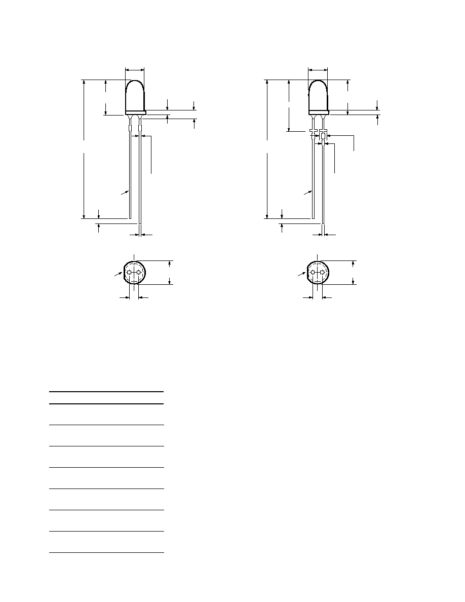
Package Dimensions
A
B
Notes:
1. All Dimensions are in millimeters (inches).
2. Leads are mild steel, solder dipped.
3. Tapers shown at top of leads (bottom of lamp package) indicate an epoxy meniscus that may extend about 1mm (0.040 in.) down the leads.
4. Recommended PC board hole diameters:
∑ Lamp package A without standoffs: Flush mounting at base of lamp package = 1.143/1.067 (0.044/0.042).
∑ Lamp package B with standoffs: Mounting at lead standoffs = 0.965/0.889(0.038/0.035).
5. For dome height above lead stand-off seating plane, d, lamp package B. See table.
Part Number
d
HLMP-xx10
12.37
±
0.25
(0.487
±
0.010)
HLMP-xx17
12.43
±
0.25
(0.489
±
0.010)
HLMP-xx26
12.52
±
0.25
(0.493
±
0.010)
HLMP-xx32
11.96
±
0.25
(0.471
±
0.010)
HLMP-xx18
12.60
±
0.25
(0.496
±
0.010)
HLMP-xx27
11.59
±
0.25
(0.446
±
0.010)
HLMP-xx33
11.99
±
0.25
(0.472
±
0.010)
2.35 (0.093)
MAX.
5.80 ± 0.20
(0.228 ± 0.008)
5.00 ± 0.20
(0.197 ± 0.008)
31.60
(1.244)
MIN.
0.70 (0.028)
MAX.
1.00
(0.039)
MIN.
2.54 ± 0.38
(0.100 ± 0.015)
0.50 ± 0.10
(0.020 ± 0.004)
SQ. TYP.
CATHODE
LEAD
CATHODE
FLAT
8.71 ± 0.20
(0.343 ± 0.008)
1.14 ± 0.20
(0.045 ± 0.008)
1.14 ± 0.20
(0.045 ± 0.008)
5.00 ± 0.20
(0.197 ± 0.008)
31.60
(1.244)
MIN.
0.70 (0.028)
MAX.
1.00
(0.039)
MIN.
8.71 ± 0.20
(0.343 ± 0.008)
0.50 ± 0.10
(0.020 ± 0.004)
SQ. TYP.
CATHODE
LEAD
d
1.50 ± 0.15
(0.059 ± 0.006)
5.80 ± 0.20
(0.228 ± 0.008)
2.54 ± 0.38
(0.100 ± 0.015)
CATHODE
FLAT
