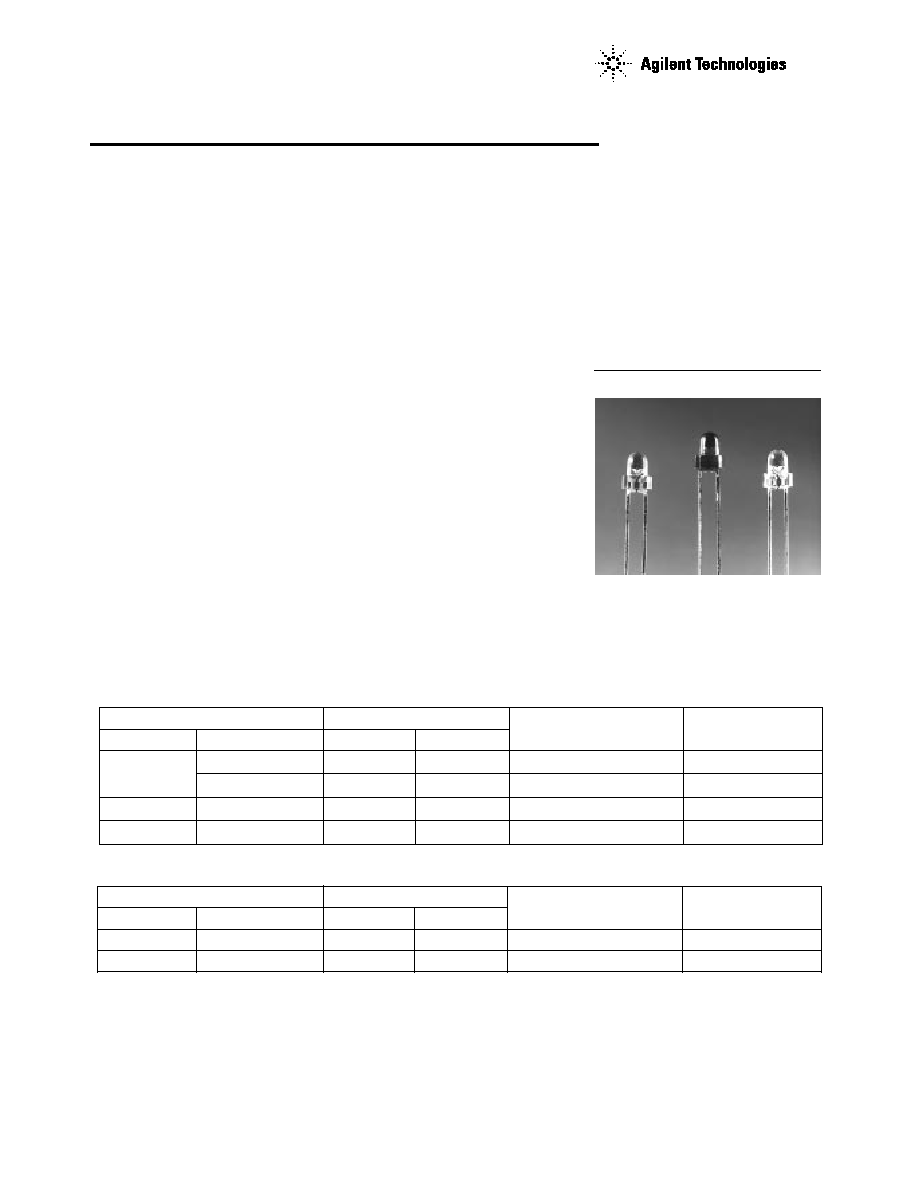
T-1 (3 mm) Auto Insertable
LED Lamps
Technical Data
HLMP-N305
HLMP-N405
HLMP-NG0x
HLMP-NJ01
HLMP-NL06
Features
∑ T-1 (3 mm) Auto Insertable
Package
∑ AlInGaP SunPower Intensity
∑ High Light Output
∑ Tinted Diffused and Tinted
Non-diffused Lens Options
∑ Wide Viewing Angle
∑ Variety of Colors
∑ Available with Straight
or Formed Lead Tape and
Reel Options
Description
This family of 3 mm LED Lamps is
capable of withstanding automatic
insertion and wave soldering
processes.
Designed with a thick epoxy flange
and soft leadframe material, it is
ideal for clinch and cut operations.
Applications
∑ General Purpose
∑ High Volume Manufacturing
Note:
1. 2
1
/
2
is the off axis angle where the luminous intensity is
1
/
2
the on axis intensity.
Device Selection Guides
High Brightness Lamps Package
Luminous Intensity,
Viewing Angle,
Color
Part Number
Tinted
Diffused
Min. Iv @ 20 mA
2
1
/
2
Red
HLMP-NG05
µ
90.2
45
HLMP-NG07
µ
90.2
60
Orange
HLMP-NJ01
µ
138.0
45
Amber
HLMP-NL06
µ
96.2
60
High Efficiency Lamps Package
Luminous Intensity,
Viewing Angle,
Color
Part Number
Tinted
Diffused
Min. Iv @ 10 mA
2
1
/
2
GaP Yellow
HLMP-N305
X
14.7
45
GaP Orange
HLMP-N405
X
13.8
45
2
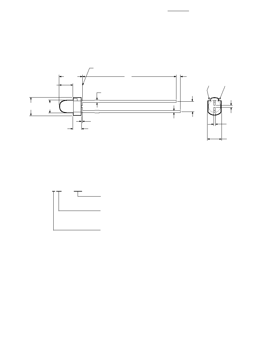
Package Dimensions
2.0 (0.08) REF.
0.4 ± 0.2
(0.01 ± 0.01)
2.5 ± 0.3
(0.10 ± 0.01)
0.45 ± 0.10
(0.02 ± 0.007)
0.4 ± 0.2
(0.02 ± 0.01)
0.4
+ 0.1
0
(0.2
+ 0.00
- 0.00
)
3.4 ± 0.2
(0.13 ± 0.01)
CATHODE MARKS
0.65 (0.03) MAX.
3.1 ± 0.2
(0.12 ± 0.01)
4.4 ± 0.3
(0.17 ± 0.01)
3.5 ± 0.3
(0.14 ± 0.01)
5.9 ± 0.5
(0.23 ± 0.02)
23.0
(0.91)
1.0 ± 0.5
(0.04 ± 0.02)
SEATING PLANE
NOTES:
1. ALL DIMENSIONS ARE IN MILLIMETERS (INCHES).
2. LEADS ARE MILD STEEL. SOLDER COATED.
3. EPOXY MENISCUS OF 0.8 mm (0.03 in.) MAXIMUM
MAY EXTEND TO THE LEADS.
Part Numbering System
HLMP - N x xx # xxx
Mechanical Option
002: Tape & Reel, Straight Leads
Viewing Angle Options
01: 45 Degree
05: 45 Degree
06, 07: 60 Degree
Color Options
3: GaP Yellow
4: GaP Orange
G: AlInGaP Red
J: AlInGaP Orange
L: AlInGaP Amber
3
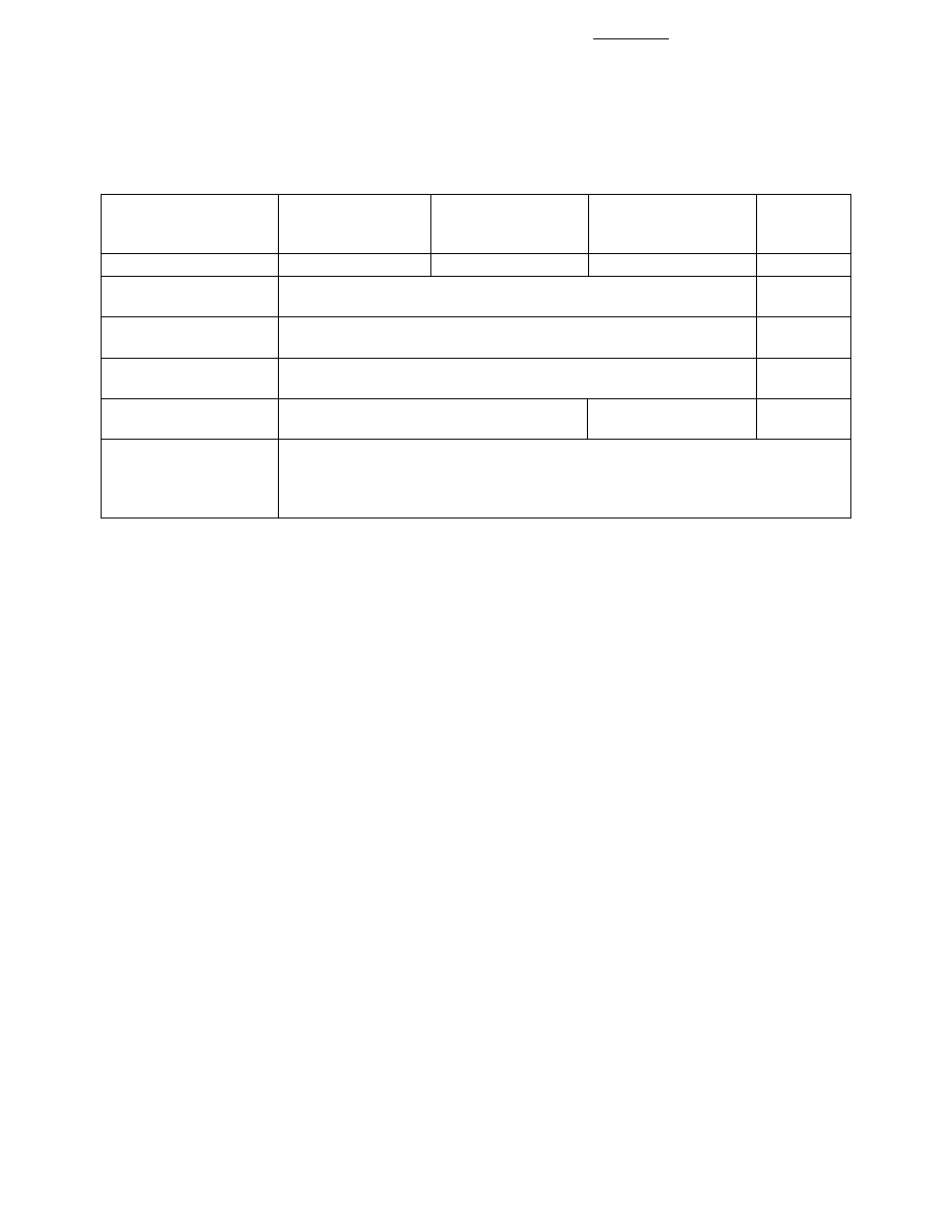
Absolute Maximum Ratings at T
A
= 25 ∫C
A1InGaP
Amber, Orange
Parameter
Orange
Yellow
& Red
Units
DC Forward Current
[1]
30
20
30
[2,3]
mA
Reverse Voltage
5
V
(Ir = 100
µ
A)
Junction Temperature,
110
∞
C
T
jmax
Storage Temperature
-40 to +85
∞
C
Range
Operating Temperature
-20 to +85
-40 to +85
∞
C
Range
Lead Soldering A) DIP/DRAG Soldering: 260
∞
C for 5 seconds
Temperature B) Wave Solder Temperature: 245
∞
C for 3 seconds
[1.6 mm (0.063 in.)
from seating plane]
Notes:
1. See Figure 4 for maximum current derating vs. ambient temperature.
2. Suggested minimum DC current: 10 mA
3. Maximum Peak Pulsed Forward Current: 50 mA, 30 mA average.
4
Notes:
1. The luminous intensity, lv, is measured at the mechanical axis of the lamp package. The actual peak of the spatial radiation pattern
may not be aligned with this axis.
2. The dominant wavelength,
d, is derived from the CIE Chromaticity Diagram and represents the color of the device.
3. The radiant intensity, le, in watts per steradian, may be found from the equation le = lv/
v
, where lv is the luminous intensity in
candelas and
v
is the luminous efficacy in lumens/watt.
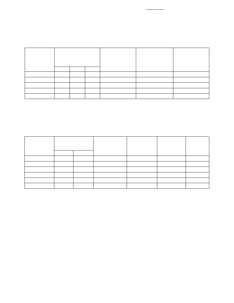
Electrical Characteristics at T
A
= 25 ∫C
Capacitance
Speed of Response
Forward
C (pF)
s
(ns)
Voltage
Vf = 0,
Thermal
Time Constant
Vf (Volts)
f = 1 MHz
Resistance R
J-PIN
e
-t
/
s
Part Number
Typ.
Max.
If (mA)
Typ.
(
∞
C/W)
Typ.
HLMP-N30x
2.00
2.6
10
15
290
90
HLMP-N40x
1.90
2.6
10
4
290
280
HLMP-NLO6
[1]
2.02
2.4
20
40
240
20
HLMP-NG0x
[1]
1.90
2.4
20
40
240
20
HLMP-NJ01
1.98
2.4
20
40
240
20
Note:
1. Please contact your Agilent Sales Representative about operating currents below 10 mA.
Optical Characteristics at T
A
= 25 ∫C
Luminous
Typ. Dominant
Efficacy
Luminous Intensity
Typ. Peak
Wavelength
Typ. Spectral
Width
Part Number
Min.
If (mA)
Wavelength (nm)
(nm)
Half Width
(lm/W)
HLMP-NG05
90.2
20
635
626
17
150
HLMP-NG07
90.2
20
635
626
17
150
HLMP-NJ01
138.0
20
609
605
17
370
HLMP-NL06
96.2
20
592
590
17
480
HLMP-N305
14.7
10
583
585
36
500
HLMP-N405
13.8
10
600
602
37
380
5
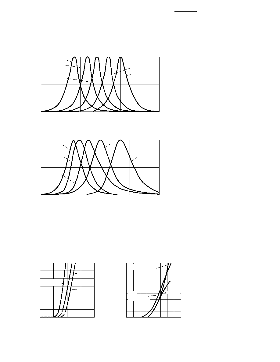
RED-ORANGE
AlInGaP RED
WAVELENGTH ≠ nm
RELATIVE INTENSITY
1.0
0.5
0
550
600
650
700
AMBER
ORANGE
HIGH BRIGHTNESS LAMPS
DH AlGaAs RED
ORANGE
HIGH
EFFICIENCY
RED
WAVELENGTH ≠ nm
RELATIVE INTENSITY
1.0
0.5
0
500
550
600
650
700
YELLOW
EMERALD GREEN
HIGH
PERFORMANCE
GREEN
HIGH EFFICIENCY LAMPS
0
90
70
60
40
20
I F
≠ FORWARD CURRENT ≠ mA
1.5
3.5
2.5
0.5
VF ≠ FORWARD VOLTAGE ≠ V
0
4.0
YELLOW
HIGH EFFICIENCY LAMPS
HIGH
EFFICIENCY
RED/ORANGE
GREEN,
EMERALD GREEN
1.0
2.0
3.0
10
30
50
80
Figure 1. Relative Intensity vs. Peak Wavelength.
Figure 2. Forward Current vs. Forward Voltage.
0
70
60
40
20
I F
≠ FORWARD CURRENT ≠ mA
VF ≠ FORWARD VOLTAGE ≠ V
1.0
3.0
AMBER
HIGH BRIGHTNESS LAMPS
DH AsAlGaAs
RED
1.5
2.0
2.5
10
30
50
AlInGaP
RED